产品管理-神州数码DLink系列产品2 精品
D-Link DVR 产品说明书

for Dial-Up Connection of DVRPPPoE(Point to Point Protocol over Ethernet) Setting Guide Manual(Rev. 2004.02.09)CONTENTSCONTENTSSetting for the DVR Server Computer : <Incoming Connection Setting>Case1. Windows 98, ME............................................................................................................... Case2. Windows 2000.................................................................................................................. Case3. Windows XP.....................................................................................................................3 6 11Setting for the DVR Client Computer: <Dial-Up Connection Setting & How to Connect to the DVR Server>Case1. Windows 98, ME............................................................................................................... Case2. Windows 2000.................................................................................................................. Case3. Windows XP.....................................................................................................................16 20 25Notice 1: How to know the User name registered in the DVR Server Computer............... Notice 2: How to find out the IP address of the DVR Server Computerat the Client................................................................................................................30 31DVR ServerWindows98,ME <Incoming Connection Setting> ComputerThis Setting is to accept incoming connection from DVR Client, so apply only to the DVRServer Computer1) On the Windows Desktop, select the ‘Start’ -> ‘Settings’ -> ‘Control Panel’.2) Double-click the ‘Add/Remove Programs’.3) Select ‘Windows Setup’ tap and check the ‘Communications’ component and click‘Details’.DVR Server Computer4) Check the ‘Dial-up Server’ component and click ‘OK’.5) Then, on the Windows Desktop, select the ‘Start’ -> ‘Programs’ -> ‘Accessories’ -> ‘Communications’ -> ‘Dial-up Networking’.6) Click the ‘Connections’-> ‘Dial-up Server’ in Menu, and then the ‘Dial-up Server’ window appears for ‘Incoming Connections’. Click ‘Next’.‘Change Password’ and register new password to allow caller access. Click ‘OK’.‘Server Type’ and confirm the type of Dial-Up Server. Click ‘OK’9) Then you can confirm that the Status is changed ‘Idle’ to ‘Monitoring’10) Then you can confirm that the Dial-Up Server Icon ()is created on the Task bar.DVR ServerWindows2000 <Incoming Connection Setting> ComputerThis Setting is to accept incoming connection from DVR Client, so apply only to the DVRServer Computer.1) On the Windows Desktop, select the ‘Start’ -> ‘Programs’ -> ‘Accessories’ ->‘Communications’ -> ‘Network and Dial-up Connections’.2) Double–click the ‘Make New Connection’, and then the ‘Network Connection Wizard’ isrun for ‘Incoming Connections’. Click ‘Next’.4) Select the Devices for Incoming Connections ( ), and click ‘Next’.5) Select the ‘Do not allow virtual private connections’ ( ), and click ‘Next’.users (Client) can connect to DVR Server system in this computer.To add new user, click ‘Add’ and register new user’s name and password. Click ‘OK’.Then you can confirm a new user registered.Select the users allowed to connect to this computer( ), and click ‘Next’.8) In this step, assign specified TCP/IP addresses for DVR system communications.the ‘Allow callers to access my local area network’( ),and select Specify TCP/IP addresses’( ). Then, write [100.0.0.1] in From and [100.0.0.2] in To Click ‘OK’.9) Windows has finished installing for Incoming Connection. Click ‘Finish’.Dial-up Connection’2) The ‘Network Connection Wizard’ is run for ‘Incoming Connections Setting’. Click ‘Next’.3) Select the ‘Set up an advanced connection’ ( ), and click ‘Next’.5) Select the Devices for Incoming Connections ( ), and click ‘Next’.6) Select the ‘Do not allow virtual private connections’ ( ), and click ‘Next’DVR ServerComputer7) In this step, select the users allowed to connect to this computer . Only the allowedusers (Client) can connect to DVR Server system in this computer.To add new user, click ‘Add’ and register new user’s name and password. Click ‘OK’.Then you can confirm a new user registered.Select the users allowed to connect to this computer ( ), and click ‘Next’9) In this step, assign specified TCP/IP addresses for DVR system communications.the ‘Allow callers to access my local area network’( ),andTCP/IP addresses’( ). Then, write [100.0.0.1] in From and [100.0.0.2] . Click ‘OK’.10) Windows has finished installing for Incoming Connections. Click ‘Finish’.DVR ServerComputer11) Then you can confirm the ‘Incoming Connections’ icon is created in ‘Network Connections’.Windows98,ME <Dial-up Connection Setting>DVR ClientComputerThis Setting is to connect to DVR Server, so apply only to the DVR Client Computer1) On the Windows Desktop, select the ‘Start’ -> ‘Programs’ -> ‘Accessories’ ->‘Communications’ -> ‘Dial-up Networking’.2) Double–click the ‘Make New Connection’, and then the ‘Make New Connection’window is displayed.phone number of the DVR Server computer you want to connect click ‘Next’.The ‘Dial-up Connection’ is the Point to Point Communication. So, the only one DVR Client can connect to the only one DVR Server by ‘Dial-up Connection’. )5) Click ‘Finish’. You have successfully created a new Dial-Up Networking connection.6) Then you can confirm the ‘Dial-up Connection’ icon is created with specified name in ‘Dial-up Networking’ and on Windows Desktop.(of the DVR Server computer2) Connecting the DVR Server computer by Dialing to phone number of the DVR ServerAccording to the case of fault on ‘Dial-up Connection’ setupCommunication line, error can be caused.)DVR ClientWindows2000 <Dial-up Connection Setting>ComputerThis Setting is to connect to DVR Server, so apply only to the DVR Client Computer1) On the Windows Desktop, select the ‘Start’ -> ‘Programs’ -> ‘Accessories’ ->‘Communications’ -> ‘Network and Dial-up Connections’.2) Double–click the ‘Make New Connection’, and then the ‘Network Connection Wizard’ isrun for ‘Dial-up Connections’. Click ‘Next’.Write the phone number of the DVR Server computer you want to connect to, and The ‘Dial-up Connection’ is the Point to Point Communication. So, the only one DVR Client can connect to the only one DVR Server by ‘Dial-up Connection’. )‘For all users’ ( ), and click ‘Next’.7) Then you can confirm the ‘Dial-up Connection’ icon is created with specified name in‘Network and Dial-up Connection’ and on Windows Desktop ( ).8) Among the menu shown by clicking the ‘Dial-up Connection’ icon with the right button of mouse, click the ‘Properties’. Select ‘Security’ tap and click ‘Settings’.‘Allow older MS-CHAP version for Windows 95 servers’10) Window for setting confirmation is displayed as follows. Click ‘Yes’.11) Finish the ‘Dial-Up Connection Setting’ by clicking ‘OK’ on the ‘Dial-Up Connection‘Dial-up Connection’ icon (of the DVR Server computer2) Connecting the DVR Server computer by Dialing to phone number of the DVR ServerAccording to the case of fault on ‘Dial-up Connection’ setupCommunication line, error can be caused.)( ->2) The ‘Network Connection Wizard’ is run for ‘Dial-up Connection Setting’. Click ‘Next’.the ‘Connect to the Internet’ ( ), and click ‘Next’.5) Select the ‘Connect using a dial-up modem’ ( ), and click ‘Next’the name you want to use for this connection.Icon of this connection created with this name. Click ‘Next’.Write user name and password registered in ‘Incoming Connections’ of the DVR Server computer.the ‘Use this account name and password when anyone connectsfrom this computer’( ),‘Make this the default Internet connection’(‘Turn on Internet Connection Firewall for this connection’( ). Click ‘Next’.10) Then you can confirm the ‘Dial-up Connection’ icon is created with specified name in‘Network Connections’ and on Windows Desktop.Connection’ iconregistered in ‘Incoming Connections’ of the DVR Server computer.2) Connecting the DVR Server computer by Dialing to phone number of the DVR ServerAccording to the case of fault on ‘Dial-up Connection’ setup or condition of Communication line, error can be caused.)( ->window is displayed as follows. Here, you can see the 3) When you are dialing to the DVR Server Computer,should type this name in ‘User name’.‘IP Configuration’window is appeared. Here, you can find out the IP assigned of this computer (Client) by dial-up connection.find out the IP address of the XDVR Server Computer connectedon the analogy of the IP address assigned of this computer (Client).。
神州数码DCVP-1000S_V2_用户手册-200810

4.4.3 清除呼叫详细记录....................................................................................... 4-8
4.5
有效分机............................................................................................................... 4-8
1. 产品概述............................................................................................................................... 1-1
1.1
文档说明............................................................................................................... 1-1
4.2.4 VoIP 信息...................................................................................................... 4-3
4.3 事件|告警............................................................................................................. 4-3
4.6
活跃呼叫............................................................................................................... 4-8
神州数码设备配置总结.doc
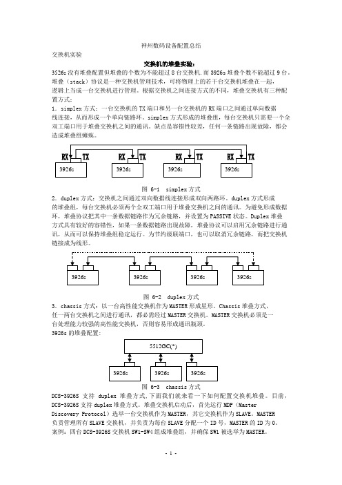
神州数码设备配置总结交换机实验交换机的堆叠实验:3526s没有堆叠配置但堆叠的个数为不能超过8台交换机.而3926s堆叠个数不能超过9台。
堆叠(stack)协议是一种交换机管理技术,可将物理上的若干台交换机堆叠在一起,逻辑上当成一台交换机进行管理。
根据交换机之间连接方式的不同,堆叠交换机有三种配置方式:1.simplex方式:一台交换机的TX端口和另一台交换机的RX端口之间通过单向数据线连接,从而形成一个单向链路环。
simplex方式形成的堆叠组,每台交换机只需要一个全双工端口用于堆叠交换机之间的通讯。
缺点是容错性较差,任何一条链路出现故障,都会造成堆叠组瘫痪。
图 6-1 simplex方式2.duplex方式:交换机之间通过双向数据线连接形成双向两路环。
duplex方式形成的堆叠组,每台交换机必须两个全双工端口用于堆叠交换机之间的通讯。
为避免形成数据环,堆叠协议把其中一条数据链路作为冗余链路,并设置为PASSIVE状态。
Duplex堆叠方式具有较好的容错性,如果一条数据链路出现故障,堆叠协议可以启用冗余链路进行通讯,从而可以保持堆叠组稳定运行。
为节约级联端口,也可以取消冗余链路,而把交换机链接成为线形。
图 6-2 duplex方式3.chassis方式:以一台高性能交换机作为MASTER形成星形。
Chassis堆叠方式,任一两台交换机之间进行通讯,都必需经过MASTER交换机。
MASTER交换机必须是一台处理能力较强的高性能交换机,否则容易形成通讯瓶颈。
3926s的堆叠配置:图 6-3 chassis方式DCS-3926S支持duplex堆叠方式,下面我们就来看一下如何配置交换机堆叠。
目前,DCS-3926S支持duplex堆叠方式。
堆叠交换机启动后,首先运行MDP(MasterDiscovery Protocol)选举一台交换机作为MASTER,其它交换机作为SLAVE。
MASTER负责管理所有SLAVE交换机,并负责为每台SLAVE分配一个ID号,MASTER的ID为0。
02-神州数码无线产品配置指导

2016/5/5
AC对AP下发配置的逻辑
2016/5/5
配置架构说明
• 每个AP关联一个profile,默认关联到profile 1上。 • network 1-1024为全局公共配置。对于AP而言,每个VAP都唯一对 应一个network,AC上面默认有16个network(1-16),与vap的0-15 对应。 • radio 1对应AP上2.4Ghz工作频段,radio 2对应AP上5Ghz工作频段。
神州数码无线产品配置指导
(售前、售后工程师技术培训)
培训目标
通过本次培训,使工程师掌握DCN自研无线产品的基本配
置方法和注意事项,能够进行一般项目的实施、调试与维
护。
2
Part 1 AP基本配置命令
AP登陆用户名和密码均为admin。
默认IP地址为192.168.1.10
默认情况下DHCP开启。 静态地址设置: set management static-ip 192.168.10.1 开/关DHCP:
SSID
vap 0
network 1
加密
VLAN SSID 加密 VLAN SSID
vap 15
network 16
AP-N
hwtype
vap 0
radio 2
network 1
加密
VLAN SSID 加密 VLAN
AP-X profile 16 AP-Y
vap 15
network 16
AC对AP下发配置的逻辑
9
AP注册方式 -- 报文分类
报文类型 协议类型 UDP 管理报文 TCP 集中式隧道报文 UDP 57777 Keepalive、AP配置下发等(加密) 集中转发时所有用户数据报文 协议端口号 57776 举例 自动发现报文、AP注册报文等
神州数码无线产品配置指导(PPT51张)

AC三层发现AP
• AC根据AP的IP地址单播发现AP的方式。
• AC上面配置三层发现IP地址列表,AC根据列表中的
地址逐个发现AP。
配置方法
• 将AP的IP地址加入到三层发现IP列表
• AC(config-wireless)#discovery ip-list 192.168.2.10
• 查看已配置的IP发现列表
AC的无线功能 • 开启无线功能的条件:AC上有UP的无线IP地址 • 无线IP地址的来源:AC上面loopback接口或者UP的三层接口 的IP地址。
• 无线IP地址的配置方式:动态选取和静态指定,动态选取的
IP优先级高于静态指定的IP优先级(实际项目中建议选用静
态指定)
动态选取无线IP地址
• 动态选取无线IP地址的原则:优先选择接口ID小的
无线产品配置指导
张帆 2013年5月
Part 1 AP配置管理
• AP注册管理 无线控制器开启无线功能 二层模式 三层模式 • AC常用功能配置方法 配置架构 SSID设置 用户vlan设置 无线加密设置 转发模式设置 射频管理
AC上开启无线功能
• AC上无线功能默认是关闭的,AC能够管理AP的前提是开启
AC#show wireless discovery ip-list IP Address Status --------------- -----------------192.168.2.10 Discovered
AP注册认证方式
•AP注册到AC时,AC需要对AP进行认证。
•主要认证方式:
–MAC认证:通过检查AP的mac地址来决定AP是否能够注册到AC上。默 认的认证方式。AC上面通过ap database来添加AP的mac地址。大规模 部署时比较麻烦。 –None:免认证,即AP自动注册,便于部署。推荐使用这种方式。 –Pass-Phase认证:密码认证,AC和AP比对密码,密码一致时AP可以注 册到AC上。AP需要做配置,使用不便,用的较少。
神州数码DCN DCWL-ZF-7900系列AP用户手册-V2.1

慢速闪绿色:此meshAP正在搜索上行链路,或正在尝试与无线控制器建立链接。
灭:Mesh网络禁用且无线服务不可用。
4
电源指示灯
灭:电源未加电,或者AP未连接到电源。
红色: AP正在启动过程中。
绿色:AP已启动完毕,正常使用。
5
5GHz外接天线接口
5
HARD RESET按钮
使用尖头针,按住此按钮,重启设备并恢复出厂设置:
-按一下,重新启动设备
-连续按住6秒以上,设备恢复出厂设置。
警告:恢复出厂设置将清空所有配置,包括IP地址,密码,ACL设置以及无线设置。
6
滑动门
保护后面板的端口、按钮。
DCWL-ZF-7962的指示灯如图1-5所示。
图1-2DCWL-ZF-7962的指示灯
快速闪烁绿色(每秒闪烁2次):此AP正接受无线控制器管理,且当前正在接受配置下发或正在进行固件升级。
3
2.4G (WLAN)
绿色:无线服务启用并至少有一个无线客户端连接到此AP。
闪烁绿色(每秒闪烁2次):无线服务启用,但没有无线客户端连接到此AP。
灭:无线服务未启用。
4
5G (WLAN)
绿色:无线服务启用并至少有一个无线客户端连接到此AP。
DCWL-ZF-7962OT提供了2个N-female型5GHz外接天线接口,最高可外接14dBi外接天线,以扩展无线覆盖范围。
6
直流电接口
AP除了可实现PoE供电,也可以使用直流电供电。
2
2
AP可以单独管理,也可以配合DCN无线控制器通信,实现集中管理。
本节介绍了当AP配合DCN无线控制器实现集中管理的初始步骤。
神州数码LinkManager_NM网络管理系统产品彩页-20110506

LinkManager NM网络管理系统LinkManager NM是神州数码网络基于多年开发与服务经验,推出的一款基于Windows平台的新一代综合性网络管理软件。
LinkManager NM以易用、实用为开发原则,定位于对网络和业务应用实施深入而全面的监控,把网络拓扑发现、资源管理、设备管理、终端管理、性能管理、故障分析、异常流量监测、服务器管理、数据库管理、WEB监控等融为一体。
LinkManager NM通过可视化、仪表化、智能化的网络导航管理模式,将复杂的网络管理工作简单化、人性化,让网管软件带动用户来熟悉与掌控自己的网络,大大降低了用户技术入门的门槛,助广大网管人员轻松驾驭网络。
主要特性即开即用(Out Of The Box):NM可即开即用,安装简便,无需用户再额外查阅手册。
一站式导航(One-Stop Navigation):NM的导航系统可以引导用户一步到位地建立起网络管理的全局体系。
智能化(Intelligence):自动发现网络及其承载的服务,自动配置监控对象及性能阀值,自动分析故障并发出告警。
多维度(Multi-Dimension):从路由、设备、终端、流量、故障等方面多角度、细颗粒度地监控、管理网络。
全局观(Overview):以Portal的方式展现,帮助网络管理人员一目了然地掌控网络的运行全局。
宽屏化(Widescreen):国内首款宽屏设计,便于更多信息的集中显示。
个性化(Personality):用户可根据需要建立起自己的特色网络管理中心,并配制个性化的监控界面。
主要功能●拓扑自动发现及管理LinkManager NM可以自动、准确、及时地发现各类大型网络的拓扑结构。
并且可根据管理员设置自动完成更新。
LinkManager NM可通过Snmp、Icmp、Arp、NetBios、Traceroute、Telnet等方式自动发现识别网络拓扑,并根据用户的视角不同提供多种网络拓扑视图:网络拓扑:据网络层的角度来分析和展现被管网络各个子网之间的连接关系物理拓扑:反映了实际连接的二层物理拓扑子网拓扑:从链路层分析展现接入终端的子网拓扑WEB拓扑:WEB视图允许用户自定义拓扑视图,提供另外一种更直观的查看视角。
神州数码DCN全线产品及参数
注意: license升级需呈递增型方式进行。例如: 客户原本配置了DCWL-FM-0100,但由于业务需求,需扩展到可最多管理500台AP, 这 FM-0250和DCWL-FM-0500。
神州数码网络有限公司WLAN产品参数
产品描述
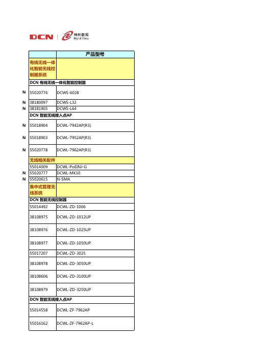
DCN有线无线一体化智能控制器(默认含32台AP管理许可,最多可支持256台AP,64台AC集群, 1+1, N+1, N+N冗余备份) DCN有线无线一体化智能控制器专用升级许可 (含32台AP升级许可) DCN有线无线一体化智能控制器专用升级许可 (含64台AP升级许可) DCN 802.11n室内增强型无线接入点AP (2.4GHz 单路单频,3x3MIMO,胖/瘦模式自动切换、 天线可拆卸,PoE和本地供电) DCN 802.11a/bgn室内增强型无线接入点AP (2.4GHz/5GHz 单路双频,3x3MIMO,胖/瘦模式 自动切换、天线可拆卸,PoE和本地供电) DCN 802.11abgn室内增强型无线接入点AP (2.4GHz & 5GHz 双路双频,3x3MIMO,胖/瘦模式 自动切换、天线可拆卸,PoE和本地供电) 10/100/1000Mbps单端口802.3af PoE模块 室内AP吸顶、挂壁防盗安装套件(适用于R3版本的AP) N头-SMA头转接线缆,30厘米长
DCN 智能无线接入点AP 55014558 55016162 55008812 55016163 DCWL-ZF-7962AP DCWL-ZF-7962AP-L DCWL-ZF-7942AP DCWL-ZF-7942AP-L
55008813
DCWL-ZF-2942AP
55014310
DCWL-ZF-2942OT
- 1、下载文档前请自行甄别文档内容的完整性,平台不提供额外的编辑、内容补充、找答案等附加服务。
- 2、"仅部分预览"的文档,不可在线预览部分如存在完整性等问题,可反馈申请退款(可完整预览的文档不适用该条件!)。
- 3、如文档侵犯您的权益,请联系客服反馈,我们会尽快为您处理(人工客服工作时间:9:00-18:30)。
目录
服务器用产品
▪DGE-500SX——千兆SX以太网卡,SC光纤接口、多模 ▪DFE-570TX——4口RJ-45 10/100M服务器卡、具有Port Trunking功能 ▪DFE-500FX——100M PCI快速光纤以太网卡(SC光纤接口)
用户端产品
▪DFE-530TX——10/100M PCI快速以太网卡、具有远程唤醒功能 ▪DE-220PT、DE-528T——10M ISA/PCI以太网卡、RJ-45单口 ▪DFE-680TX——10/100M CardBus笔记本用网卡、RJ-45单口
核心层主干交换机
DES-6000 可网管机箱式千兆以太网交换机
主要特性及卖点
▪8个插槽, 端口密度高,可灵活选择多种传输介质:
最多128个10/100Mbps 端口,或96个100M光纤端口,或16个千兆网端口
▪支 持 端 口 干 路 ( Port Trunking ) 、 VLAN 、 流 量 控 制 ( Flow Control)、端口镜像(Port Mirror),可提高网络性能和可监控性 ▪支持IGMP协议,可在组播(如视频点播)时有效降低网络流量 ▪支持SNMP及RMON网管 协议 ▪21.3GBps大容量背板带宽 ▪19”机架式安装 ,支持热插拔冗余电源,可靠性极高 ▪良好的售后服务
核心层主干交换机
DES-6000 可网管机箱式千兆以太网交换机
技术指标
▪交换方式:存储转发 ▪转发速率:线速 ▪背板带宽:21.3Gbps ▪MAC地址:12K ▪支持的双工模式:全双工或半双工
核心层主干交换机
DES-6000 可网管机箱式千兆以太网交换机
技术指标 ▪支持的网线类型: 10Base-T: 3,4或5类非屏蔽双绞线(UTP)(≤100m) EIA/TIA-568 100 欧 屏 蔽 双 绞 线 ( STP ) (≤100m) 100Base-TX: 2对或4对5类非屏蔽双绞线(UTP)(≤100m) EIA/TIA-568 100 欧 屏 蔽 双 绞 线 ( STP ) (≤100m) 100Base-FX: 62.5 μm多模光纤(≤2km)
核心层主干交换机
DES-6000 可网管机箱式千兆以太网交换机Biblioteka 前面板第1个插槽插管理模块
双电源
第 2—9 个 插 槽 换模块插槽
核心层主干交换机
DES-6000 可网管机箱式千兆以太网交换机
技术指标
▪符合IEEE802.3 10Base-T,IEEE802.3u 100Base-TX/FX,IEEE802.3z 1000Base-SX/LX标准 ▪提供9个扩展插槽,其中第一个插槽用来插管理模块,其余8个插槽可 选插:
技术指标
▪支持多数常用标准和协议:
支持IEEE802.1q VLAN(Static VLAN),最多支持2048组VLAN划分 支持Internet 工作组管理协议(IGMP) 支持IEEE802.1d生成树(Spanning Tree) 支持IEEE802.3x流量控制(Flow Control)、广播风暴控制 支持IEEE802.1p优先级控制(2 Priority Queuing) 支持端口干路(Port Trunking)、端口镜像(Port Mirror) 支持GARP/GVRP、GARP/GMRP协议 支持SNMP、 4组(1,2,3,9)RMON,可基于WEB页面管理
1000Base-SX: 62.5μm多模光纤(≤275m) 50μm多模光纤(≤550m)
1000Base-LX: 62.5μm多模光纤(≤550m) 50μm多模光纤(≤550m)
核心层主干交换机
DES-6000 可网管机箱式千兆以太网交换机
订货信息
产品名称 DES-6000 DES-6003 DES-6004 DES-6005 DES-6006 DES-6007 DES-6011
16端口的10/100Mbps模块 12端口100Base-FX (MT-RJ)模块 2端口1000Base-SX (MT-RJ)千兆模块 2端口 1000Base-SX (SC) 千兆模块 2端口1000Base-LX (SC) 千兆模块
核心层主干交换机
DES-6000 可网管机箱式千兆以太网交换机
其它产品
▪DFE-855TX——快速以太网转换器(100M,双绞线-光纤/SC,2Km) ▪DP-300——2个并口+1个串口10/100M快速以太网打印服务器 ▪DI-206、DI520、DI540——路由器
核心层主干交换机
DES-6000 可网管机箱式千兆以太网交换机
产品简介及适用范围 ▪8个扩展插槽,可选插千兆以太网、 10/100Mbps和100Base-FX模块,能够适应不 同网络主干应用要求; ▪DES-6000适用于高速率、高端口密度、多端 口类型的企业级大型主干网络,千兆以太网 模块可提供网络骨干的带宽。
网络结构的末梢,直接面向最终用户。这一部分的 网络设计是否成功,直接影响整个网络的正常运营 和经济效益
用户 用户
用户 用户
目录
核心层交换机
▪DES-6000——可网管机箱式千兆以太网交换机 ▪DGS-3208F、DGS3208TG——可网管千兆以太网主干交换机 ▪DES-5220TF——可网管机箱式百兆以太网主干交换机
汇聚层交换机
▪DES-3624I、DES-3624——可堆叠、支持千兆的可网管10/100Mbps交换机 ▪DES-3225G——支持千兆的可网管24口10/100Mbps交换机
接入层交换机或集线器
▪DES-1024R、DES-1016R、DES1008——10/100Mbps交换机 ▪DFE-2624X、DFE-916DX、DFE908DX——10/100Mbps集线器 ▪DE-824、DE-816、DE809、DE805——10Mbps集线器
神州数码D-Link系列产品
广州网域电脑技术有限公司
网络的三层结构体系
一、核心层 处于网络结构的顶层,应该具有高带宽传输能力、 高容错性能、高密度和高速率接入等特性
核心层
二、汇聚层
汇聚层 汇聚层
构成网络主体,在网络结构中发挥承上启下的作用,
多采用以太网快速以太网和千兆以太网混合构建 三、接入层
接入层 接入层 接入层