本实验对2950交换机VLAN配置相关的VTP
2950交换机trunk-vlan配置实例

VLAN的划分与互通实验准备工作:按照下图所示,连接实验环境。
如果没有设备,可下载Boson NetSim局域网交换与路由模拟器。
拓扑图:配置过程:说明:本实验完全在Boson Netsim模拟器上完成,下面红色下划线文字均为配置过程输入的命令。
一、交换机2950B配置1、配置交换机主机名、管理ip、默认网关Switch>enSwitch#config tSwitch(config)#hostname 2950B2950B(config)#int vlan 12950B(config-if)#ip address 172.16.10.3 255.255.255.0 //设置管理IP地址2950B(config-if)#no shut2950B(config-if)#exit2950B(config)#ip default-gateway 172.16.10.1 //设置默认网关IP地址2、配置中继口(即trunk口)2950B(config)#int f0/12950B(config-if)#switchport mode trunk2950B(config-if)#exit2950B(config)#int f0/42950B(config-if)#switchport mode trunk2950B(config-if)#exit2950B(config)#int f0/52950B(config-if)#switchport mode trunk2950B(config-if)#exit2950B(config)#3、配置vtp,把2950B交换机设置成客户机模式,2950B从2950C接收vlan信息2950B#vlan database2950B(vlan)#vtp client2950B(vlan)#vtp domain cisco4、创建Vlan2950B(vlan)#vlan 2 name sales // 将vlan 2设置名称为sales2950B(vlan)#vlan 3 name marketing // 将vlan 2设置名称为marketing 2950B(vlan)#apply2950B(vlan)#exit5、将交换机端口分配到vlan中2950B#config t2950B(config)#int f0/22950B(conf-if)#switchport mode access // 设置二层交换端口2950B(config-if)#switchport access vlan 22950B(config-if)#exit2950B(config)#int f0/32950B(conf-if)#switchport mode access // 设置二层交换端口2950B(config-if)#switchport access vlan 32950B(config-if)#exit2950B(config)#exit2950B#6、保存配置2950B#copy run start二、交换机2950C配置1、配置交换机主机名、管理ip、默认网关Switch>enSwitch#config tSwitch(config)#hostname 2950C2950C(config)#int vlan 12950C(config-if)#ip address 172.16.10.2 255.255.255.02950C(config-if)#no shut2950C(config-if)#exit2950B(config)#ip default-gateway 172.16.10.12、配置中继口(即trunk口)2950C(config)#int f0/42950C(config-if)#switchport mode trunk2950C(config-if)#exit2950C(config)#int f0/52950C(config-if)#switchport mode trunk2950C(config-if)#exit2950C(config)#3、配置vtp,把2950C交换机设置成服务器模式,2950B从2950C接收vlan信息2950C#vlan database2950C(vlan)#vtp server2950C(vlan)#vtp domain cisco4、创建Vlan2950C(vlan)#vlan 2 name sales2950C(vlan)#vlan 3 name marketing2950C(vlan)#apply2950C(vlan)#exit5、将交换机端口分配到vlan中2950C#config t2950C(config)#int f0/22950C(conf-if)#switchport mode access // 设置二层交换端口2950C(config-if)#switchport access vlan 22950C(config-if)#exit2950C(config)#int f0/32950C(conf-if)#switchport mode access // 设置二层交换端口2950C(config-if)#switchport access vlan 32950C(config-if)#exit2950C(config)#exit2950C#6、保存配置2950C#copy run start三、vlan间路由器2600配置过程1、配置路由器主机名、清除f0/0端口ip地址、启动f0/0端口Router>enRouter#config tRouter(config)#hostname trunkrouterTrunkrouter(config)#int f0/0Trunkrouter(config-if)#no ip addressTrunkrouter(config-if)#no shut2、将路由器的快速以太网端口fa0/0划分为三个子接口fa0/0.1、fa0/0.2和fa0/0.3,对每个子接口配置,并采用802.1q的数据封装。
cisco2950交换机常用命令

domain Set the name of the VTP administrative domain.
client Set the device to client mode.
server Set the device to server mode.
2950#clear mac-address-table restricted static (清除限制性MAC址表)
四、 VTP的配置
2950#vlan database (进入VLAN配置模式)
2950(vlan)#vtp ? (查看VTP的子命令)
2950#vlan database (进入VLAN配置模式)
2950(vlan)#vlan 2 (创建VLAN 2)
VLAN 2 added:
Name:VLAN0002 (系统默认名)
2950(vlan)#vtp domain wqs (设置域名)
2950(vlan)#vtp pruning (启动修剪模式)
2950#show vtp status (查看VTP设置信息)
五、配置VLAN TRUNK端口
2950(config)#int f0/11 (进入F端口)
2950(config)#ip name-server 192.168.1.1 (设置域名服务器)
2950(config)#ip domain-name (设置域名)
二、端口配置
2950(config)#int f0/1 (进入接口)
2950(config-if)#spanning-tree vlan 2 port-priority 10 (将VLAN2的端口权值设spanning-tree vlan 2 cost 30 (设置VLAN2生成树路径值为30)
实验十三配置VLAN,vtp,及端口安全性

实验七配置VLAN,VTP,及交换机的端口安全性实验目的:1、掌握VLAN的配置方法,理解VLAN的含义。
2、理解VTP的工作原理,会配置VTP。
3、会配置交换机的端口安全性。
实验设备:CISCO2950交换机三台,PC两台,网线若干。
实验内容:1、按上图将交换机和PC连接好。
Sw1 port1 ~ sw2 port1Sw1 port2 ~ sw3 port1Sw2 port2 ~ sw3 port2PC1 ~sw1 port 3PC2 ~sw3 port 3将三台交换机分别命名为SW1、SW2、SW3。
Pc1:ip—192.168.1.4/24Pc2:ip—192.168.3.5/242、查看端口转发模式:Switch#show port system3、将交换机间互联的端口模式设置为trunk.语法为:switch(config-if)#switchport mode trunk4、配置三台交换机的console 和vty密码为cisco.5、配置vtp域名为founder,sw1 的模式为server,sw2和sw3的模式为client.配置修剪。
语法为:switch#vlan databaseSwitch(vlan)#vtp domain domain-nameSwitch(vlan)#vtp client|transparent|serverSwitch(vlan)#vtp pruning6、在SW1上配置vlan2,vlan3。
并将Sw1的Port3~port10加入Vlan2。
语法为:switch(config-if)#switchport mode accessSwitch(config-if)#swtichport access vlan number将SW3上的port3~port5加入Vlan3。
7、设置vlan 管理ip及网关:vlan1—192.168.2.2/24,网关:192.168.2.1语法为:switch(config)#interface vlan numberSwitch(config-if)#ip address ip netmaskSwitch(config-if)#no shutdownSwitch(config)#ip default-gateway ipaddress8、验证配置。
2950交换机简要配置手册(中文)

2950交换机简明配置维护手册目录说明 (3)产品特性 (3)配置端口 (4)配置一组端口 (4)配置二层端口 (6)配置端口速率及双工模式 (6)端口描述 (7)监控及维护端口 (8)监控端口和控制器的状态 (8)刷新、重置端口及计数器 (10)关闭和打开端口 (10)配置VLAN (11)理解VLAN (11)可支持的VLAN (12)配置正常范围的VLAN (12)生成、修改以太网VLAN (13)删除VLAN (14)将端口分配给一个VLAN (15)配置VLAN Trunks (16)使用STP实现负载均衡 (19)配置Cluster (23)说明本手册只包括日常使用的有关命令及特性,其它未涉及的命令及特性请参考英文的详细配置手册。
产品特性2950是只支持二层的交换机支持VLAN•到250 个VLAN•支持VLAN ID从1到4094(IEEE 802.1Q 标准)•支持ISL及IEEE 802.1Q封装安全•支持IOS标准的密码保护•支持标准及扩展的访问列表来定义安全策略•支持基于VLAN的访问列表监视•交换机LED指示端口状态•SPAN及远端SPAN (RSPAN) 可以监视任何端口或VLAN的流量•内置支持四组的RMON监控功能(历史、统计、告警及事件)配置端口配置一组端口当使用interface range命令时有如下的规则:•有效的组范围:o vlan从1 到4094o fastethernet槽位/{first port} - {last port}, 槽位为0o gigabitethernet槽位/{first port} - {last port},槽位为0o port-channel port-channel-number - port-channel-number, port-channel号从1到64•端口号之间需要加入空格,如:interface range fastethernet 0/1 – 5是有效的,而interface range fastethernet 0/1-5是无效的.•interface range命令只能配置已经存在的interface vlan•所有在同一组的端口必须是相同类别的。
2950交换机上配置VLAN实例
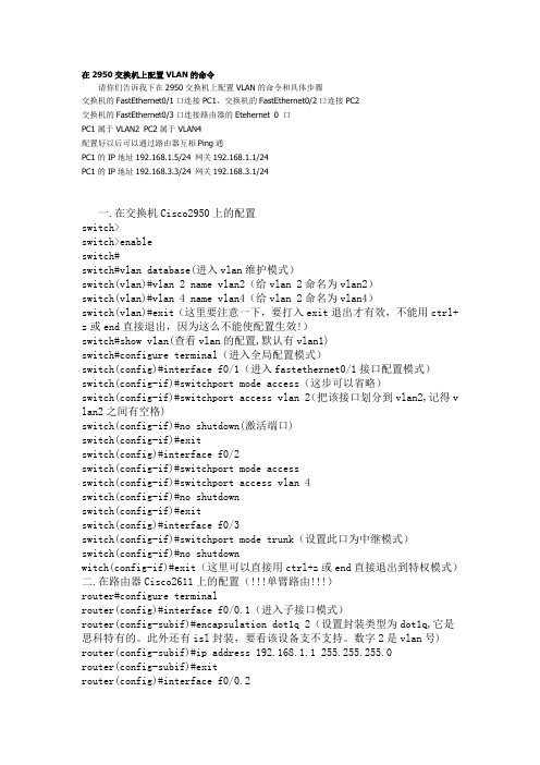
在2950交换机上配置VLAN的命令请你们告诉我下在2950交换机上配置VLAN的命令和具体步骤交换机的FastEthernet0/1口连接PC1,交换机的FastEthernet0/2口连接PC2交换机的FastEthernet0/3口连接路由器的Etehernet 0 口PC1属于VLAN2 PC2属于VLAN4配置好以后可以通过路由器互相Ping通PC1的IP地址192.168.1.5/24 网关192.168.1.1/24PC1的IP地址192.168.3.3/24 网关192.168.3.1/24一.在交换机Cisco2950上的配置switch>switch>enableswitch#switch#vlan database(进入vlan维护模式)switch(vlan)#vlan 2 name vlan2(给vlan 2命名为vlan2)switch(vlan)#vlan 4 name vlan4(给vlan 2命名为vlan4)switch(vlan)#exit(这里要注意一下,要打入exit退出才有效,不能用ctrl+ z或end直接退出,因为这么不能使配置生效!)switch#show vlan(查看vlan的配置,默认有vlan1)switch#configure terminal(进入全局配置模式)switch(config)#interface f0/1(进入fastethernet0/1接口配置模式)switch(config-if)#switchport mode access(这步可以省略)switch(config-if)#switchport access vlan 2(把该接口划分到vlan2,记得v lan2之间有空格)switch(config-if)#no shutdown(激活端口)switch(config-if)#exitswitch(config)#interface f0/2switch(config-if)#switchport mode accessswitch(config-if)#switchport access vlan 4switch(config-if)#no shutdownswitch(config-if)#exitswitch(config)#interface f0/3switch(config-if)#switchport mode trunk(设置此口为中继模式)switch(config-if)#no shutdownwitch(config-if)#exit(这里可以直接用ctrl+z或end直接退出到特权模式)二.在路由器Cisco2611上的配置(!!!单臂路由!!!)router#configure terminalrouter(config)#interface f0/0.1(进入子接口模式)router(config-subif)#encapsulation dot1q 2(设置封装类型为dot1q,它是思科特有的。
VTP协议简单实验教程

VTP协议简单实验教程一、实验准备:●Cisco 2950交换机2台。
●直通线4根。
●交叉线1根。
二、实验网络拓扑结构:➢如图所示,用2根直通线把PC11、PC21连接到交换机SW1的fa0/2、fa0/13端口上,再用2根直通线把PC12、PC22连接到交换机SW2的fa0/2、fa0/13端口上。
➢用一根交叉线把SW1交换机的fa0/1端口和SW2交换机的fa0/1端口连接起来。
测试网络连通性(自行制表)1、配置PC IP地址配置PC11计算机的IP地址为192.168.1.11,子网掩码为255.255.255.0;配置PC12计算机的IP地址为192.168.1.12,子网掩码为255.255.255.0;配置PC21计算机的IP地址为192.168.1.21,子网掩码为255.255.255.0;配置PC22计算机的IP地址为192.168.1.22,子网掩码为255.255.255.0。
2、配置SW1交换机步骤1:在PC11计算机上打开超级终端,配置SW1交换机。
设置SW1交换机为VTP服务器模式,方法如下。
步骤2:在SW1交换机上创建VLAN 10和VLAN 20,并将SW1交换机的fa0/2~fa0/12端口划分到VLAN 10,将fa0/13~fa0/24划分到VLAN 20(参照上节课试验方法),fa0/1端口默认位于VLAN 1步骤3:将SW1交换机的fa0/1端口设置为干线trunk,方法如下3、配置SW2交换机步骤1:在PC12计算机上打开超级终端,设置SW2交换机为VTP客户机模式,方法如下SW2交换机工作在VTP客户端模式,它可从VTP服务器(SW1)那里获取VLAN信息(如VLAN 10、VLAN 20等),因此,在SW2交换机上不必也不能新建VLAN 10和VLAN 20。
步骤2:将SW2交换机的fa0/2~fa0/12端口划分到VLAN 10,将fa0/13~fa0/24划分到VLAN 20,具体方法参照上一个交换机。
实验一、交换机配置STP与VTP
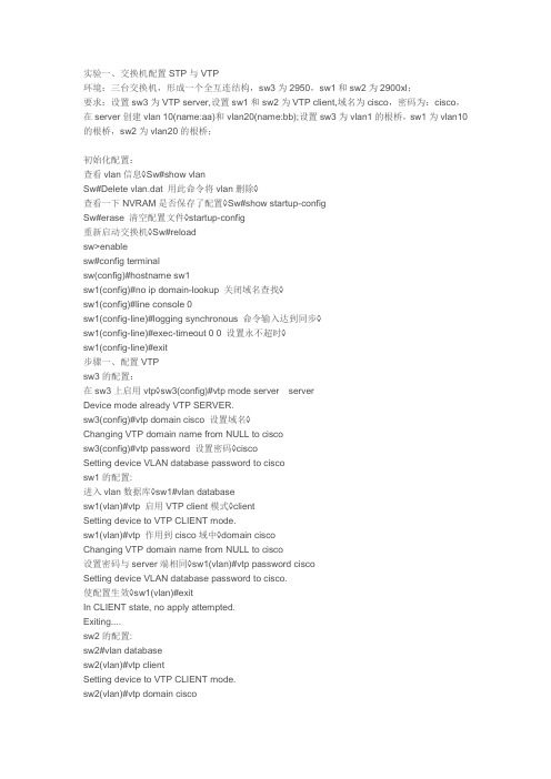
实验一、交换机配置STP与VTP环境:三台交换机,形成一个全互连结构,sw3为2950,sw1和sw2为2900xl;要求:设置sw3为VTP server,设置sw1和sw2为VTP client,域名为cisco,密码为:cisco,在server创建vlan 10(name:aa)和vlan20(name:bb);设置sw3为vlan1的根桥,sw1为vlan10的根桥,sw2为vlan20的根桥;初始化配置:查看vlan信息◊Sw#show vlanSw#Delete vlan.dat 用此命令将vlan删除◊查看一下NVRAM是否保存了配置◊Sw#show startup-configSw#erase 清空配置文件◊startup-config重新启动交换机◊Sw#reloadsw>enablesw#config terminalsw(config)#hostname sw1sw1(config)#no ip domain-lookup 关闭域名查找◊sw1(config)#line console 0sw1(config-line)#logging synchronous 命令输入达到同步◊sw1(config-line)#exec-timeout 0 0 设置永不超时◊sw1(config-line)#exit步骤一、配置VTPsw3的配置:在sw3上启用vtp◊sw3(config)#vtp mode server serverDevice mode already VTP SERVER.sw3(config)#vtp domain cisco 设置域名◊Changing VTP domain name from NULL to ciscosw3(config)#vtp password 设置密码◊ciscoSetting device VLAN database password to ciscosw1的配置:进入vlan数据库◊sw1#vlan databasesw1(vlan)#vtp 启用VTP client模式◊clientSetting device to VTP CLIENT mode.sw1(vlan)#vtp 作用到cisco域中◊domain ciscoChanging VTP domain name from NULL to cisco设置密码与server端相同◊sw1(vlan)#vtp password ciscoSetting device VLAN database password to cisco.使配置生效◊sw1(vlan)#exitIn CLIENT state, no apply attempted.Exiting....sw2的配置:sw2#vlan databasesw2(vlan)#vtp clientSetting device to VTP CLIENT mode.sw2(vlan)#vtp domain ciscoChanging VTP domain name from NULL to ciscosw2(vlan)#vtp password ciscoSetting device VLAN database password to cisco.sw2(vlan)#exitsw2#步骤二、启用干道端口sw3的配置:sw3(config)#interface fa0/23sw3(config-if)#switchport mode trunk 启用trunk端口◊sw3(config-if)#interface fa0/24sw3(config-if)#switchport mode trunksw1的配置:sw1(config)#interface fa0/23sw1(config-if)#switchport trunk encapsulation dot1q 封装干道协议◊sw1(config-if)#switchport mode trunk 启用trunk模式◊sw1(config-if)#sw1(config)#interface fa0/24sw1(config-if)#switchport trunk encapsulation dot1qsw1(config-if)#switchport mode trunksw2的配置:sw2(config)#interface fa0/23sw2(config-if)#switchport trunk encapsulation dot1qsw2(config-if)#switchport mode trunksw2(config)#interface fa0/24sw2(config-if)#switchport trunk encapsulation dot1qsw2(config-if)#switchport mode trunk步骤三、测试vtp状态及创建vlansw3的状态:显示vtp状态◊sw3#show vtp statusVTP Version : 2配置修订号◊Configuration Revision : 0Maximum VLANs supported locally : 254Number of existing VLANs : 5VTP Operating Mode : server vtp模式◊vtp域名◊VTP Domain Name : ciscoVTP Pruning Mode : DisabledVTP V2 Mode : DisabledVTP Traps Generation : DisabledMD5 digest : 0x3F 0x17 0xC8 0xB8 0x5A 0xE3 0x01 0x66 Configuration last modified by 0.0.0.0 at 0-0-00 00:00:00创建vlan:sw3(config)#vlan 10 创建VLAN10◊命名为aa◊sw3(config-vlan)#name aasw3(config-vlan)#exit 应用配置◊创建VLAN20◊sw3(config)#vlan 20sw3(config-vlan)#name bb 命名为bb◊sw3(config-vlan)#exitsw3(config)#sw3的状态:在sw3显示vtp的状态◊sw3#show vtp statusVTP Version : 2server的修订号◊Configuration Revision : 2Maximum VLANs supported locally : 254vlan也已经增加◊Number of existing VLANs : 7VTP Operating Mode : serverVTP Domain Name : ciscoVTP Pruning Mode : DisabledVTP V2 Mode : DisabledVTP Traps Generation : DisabledMD5 digest : 0x98 0x31 0xCF 0xA0 0xA7 0x17 0x73 0x66 Configuration last modified by 0.0.0.0 at 3-1-93 00:52:05sw2的状态:sw2#show vtp statusVTP Version : 2已经同步了server◊Configuration Revision : 2Maximum VLANs supported locally : 254Number of existing VLANs : 7VTP Operating Mode : ClientVTP Domain Name : ciscoVTP Pruning Mode : DisabledVTP V2 Mode : DisabledVTP Traps Generation : DisabledMD5 digest : 0x98 0x31 0xCF 0xA0 0xA7 0x17 0x73 0x66 Configuration last modified by 0.0.0.0 at 3-1-93 00:52:05sw1的vlan信息:显示vlan信息◊sw1#show vlanVLAN Name Status Ports---- -------------------------------- --------- -------------------------------1 default active Fa0/1, Fa0/2, Fa0/3, Fa0/4,Fa0/5, Fa0/6, Fa0/7, Fa0/8,Fa0/9, Fa0/10, Fa0/11, Fa0/12,Fa0/13, Fa0/14, Fa0/15, Fa0/16,Fa0/17, Fa0/18, Fa0/19, Fa0/20,Fa0/21, Fa0/22, Fa0/23, Fa0/24已经同步了vlan的信息◊10 aa active20 bb active步骤四、配置PVSTsw3(config)#spanning-tree vlan 1 root primary 设置为vlan1的根桥◊Sw1(config)#spanning-tree vlan 10 priority 4096 设置为vlan10的根桥◊Sw2(config)#spanning-tree vlan 20 priority 4096 设置为vlan20的根桥◊步骤五、显示STP的信息sw1的生成树信息:sw1#show spanning-tree brief 显示每VLAN生成树信息◊VLAN1Spanning tree enabled protocol IEEEROOT ID Priority 24577非vlan1的根桥◊Address 0007.eb06.1740Hello Time 2 sec Max Age 20 sec Forward Delay 15 secBridge ID Priority 32768Address 0030.803d.f640Hello Time 2 sec Max Age 20 sec Forward Delay 15 secVLAN10Spanning tree enabled protocol IEEEROOT ID Priority 4096为vlan10的根桥◊Address 0030.803d.f641This bridge is the rootHello Time 2 sec Max Age 20 sec Forward Delay 15 secBridge ID Priority 4096Address 0030.803d.f641Hello Time 2 sec Max Age 20 sec Forward Delay 15 secVLAN20Spanning tree enabled protocol IEEEROOT ID Priority 4096Address 00b0.645f.34c2 非vlan20的根桥◊Hello Time 2 sec Max Age 20 sec Forward Delay 15 secBridge ID Priority 32768Address 0030.803d.f642Hello Time 2 sec Max Age 20 sec Forward Delay 15 secsw2的生成树信息:sw2#show spanning-tree briefVLAN1Spanning tree enabled protocol IEEE 非vlan1的根桥◊ROOT ID Priority 24577Address 0007.eb06.1740Hello Time 2 sec Max Age 20 sec Forward Delay 15 secBridge ID Priority 32768Address 00b0.645f.34c0Hello Time 2 sec Max Age 20 sec Forward Delay 15 secVLAN10Spanning tree enabled protocol IEEEROOT ID 非vlan10的根桥◊Priority 4096Address 0030.803d.f641Hello Time 2 sec Max Age 20 sec Forward Delay 15 sec Bridge ID Priority 32768Address 00b0.645f.34c1Hello Time 2 sec Max Age 20 sec Forward Delay 15 sec VLAN20Spanning tree enabled protocol IEEEROOT ID 为vlan20的根桥◊Priority 4096Address 00b0.645f.34c2This bridge is the rootHello Time 2 sec Max Age 20 sec Forward Delay 15 sec Bridge ID Priority 4096Address 00b0.645f.34c2Hello Time 2 sec Max Age 20 sec Forward Delay 15 sec sw3的生成树信息:sw3#show spanning-treeVLAN0001Spanning tree enabled protocol ieeeRoot ID 为vlan1的根桥◊Priority 24577Address 0007.eb06.1740This bridge is the rootHello Time 2 sec Max Age 20 sec Forward Delay 15 sec Bridge ID Priority 24577 (priority 24576 sys-id-ext 1) Address 0007.eb06.1740Hello Time 2 sec Max Age 20 sec Forward Delay 15 sec Aging Time 300VLAN0010Spanning tree enabled protocol ieeeRoot 非vlan10的根桥◊ID Priority 4096Address 0030.803d.f641Cost 19Port 24 (FastEthernet0/24)Hello Time 2 sec Max Age 20 sec Forward Delay 15 sec Bridge ID Priority 32779 (priority 32768 sys-id-ext 11) Address 0007.eb06.1740Hello Time 2 sec Max Age 20 sec Forward Delay 15 sec Aging Time 300VLAN0020Spanning tree enabled protocol ieeeRoot ID 非v◊Priority 4096 lan20的根桥Address 00b0.645f.34c2Cost 19Port 23 (FastEthernet0/23)Hello Time 2 sec Max Age 20 sec Forward Delay 15 sec Bridge ID Priority 32780 (priority 32768 sys-id-ext 12) Address 0007.eb06.1740Hello Time 2 sec Max Age 20 sec Forward Delay 15 sec Aging Time 300Interface Role Sts Cost Prio.Nbr Type---------------- ---- --- --------- -------- -------------------------------- Fa0/23 Root FWD 19 128.23 P2pFa0/24 Altn BLK 19 128.24 P2p步骤六、显示当前配置结果Sw1的配置结果:sw1#show running-config!hostname sw1!spanning-tree vlan 10 priority 4096!no ip domain-lookup!interface FastEthernet0/23switchport trunk encapsulation dot1qswitchport mode trunk!interface FastEthernet0/24switchport trunk encapsulation dot1qswitchport mode trunk!endsw2的配置结果:sw2#show running-confighostname sw2!spanning-tree vlan 20 priority 4096!no ip domain-lookup!interface FastEthernet0/23switchport trunk encapsulation dot1qswitchport mode trunk!interface FastEthernet0/24switchport trunk encapsulation dot1qswitchport mode trunk!endsw3的配置结果:sw3#show running-config!hostname sw3!no ip domain-lookup!spanning-tree vlan 1 priority 24576 !interface FastEthernet0/23 switchport mode trunk!interface FastEthernet0/24 switchport mode trunk!End。
思科cisco2950交换机配置手册

2950交换机简明配置维护手册目录说明 (3)产品特性 (3)配置端口 (3)配置一组端口 (3)配置二层端口 (5)配置端口速率及双工模式 (6)端口描述 (7)监控及维护端口 (8)监控端口和控制器的状态 (8)刷新、重置端口及计数器 (10)关闭和打开端口 (10)配置VLAN (11)理解VLAN (11)可支持的VLAN (12)配置正常范围的VLAN (12)生成、修改以太网VLAN (13)删除VLAN (14)将端口分配给一个VLAN (15)配置VLAN Trunks (16)使用STP实现负载均衡 (19)配置Cluster (23)第1章说明本手册只包括日常使用的有关命令及特性,其它未涉及的命令及特性请参考英文的详细配置手册。
第2章产品特性2950是只支持二层的交换机支持VLAN•到250 个VLAN•支持VLAN ID从1到4094(IEEE 802.1Q 标准)•支持ISL及IEEE 802.1Q封装安全•支持IOS标准的密码保护•支持标准及扩展的访问列表来定义安全策略•支持基于VLAN的访问列表监视•交换机LED指示端口状态•SPAN及远端SPAN (RSPAN) 可以监视任何端口或VLAN的流量•内置支持四组的RMON监控功能(历史、统计、告警及事件)第3章配置端口3.1 配置一组端口当使用interface range命令时有如下的规则:•有效的组范围:o vlan从1 到4094o fastethernet槽位/{first port} - {last port}, 槽位为0o gigabitethernet槽位/{first port} - {last port},槽位为0o port-channel port-channel-number - port-channel-number, port-channel号从1到64•端口号之间需要加入空格,如:interface range fastethernet 0/1 –5是有效的,而interface range fastethernet 0/1-5是无效的.•interface range命令只能配置已经存在的interface vlan•所有在同一组的端口必须是相同类别的。
- 1、下载文档前请自行甄别文档内容的完整性,平台不提供额外的编辑、内容补充、找答案等附加服务。
- 2、"仅部分预览"的文档,不可在线预览部分如存在完整性等问题,可反馈申请退款(可完整预览的文档不适用该条件!)。
- 3、如文档侵犯您的权益,请联系客服反馈,我们会尽快为您处理(人工客服工作时间:9:00-18:30)。
本实验对2950交换机VLAN配置相关的VTP.VLAN和VLAN Trunk等进行配置。
1.实验目的
通过本实验,读者可以掌握以下技能:
●配置VLAN;
●通过VLAN Trunk配置跨交换机的VLAN;
●配置VTP;
●查看上述配置项目的有关信息。
2.设备需求
本实验需要以下设备;
●Cisco Catalyst 2950系列交换机2台,型号不限;
●交叉线序网线1条;
●1台终端服务器,如Cisco 2509路由器,及用于反向Telnet的相应电缆;
●1台带有超级终端程序的PC机,以及Console电缆及转接器。
3.线缆连接及配置说明
如图A-2所示,用交叉网线把C2950A交换机的FastEthernetO/24端口和C2950B交换机的FastEthernet0/24端口连接起来。
4.实验配置及监测结果
电缆连接完成后,给所有设备加电,开始进行实验。
监测清单A-4记录了本实验的操作。
监测清单A-4 配置VTP、VLAN和VLAN Trunk
第1段:配置C2950交换机的VTP和VLAN
C2950#conft
Enter configuration commands,one per line.End with CNTL/Z.
(1)在2950系列交换机上配置VTP和VLAN的方法有两种,本实验演示的是使用vlandatabase命令的一种;另一种是在全局配置模式下发出配置命令,格式与vlan database方式相似。
(2)首先使用vlan database命令进入VLAN配置模式。
在VLAN配置模式下,可以设置VTP的一系列属性,如vtp?命令所示,也可以对VLAN进行定义。
(3)把C2950A交换机设置成VTP Server模式(缺省配置),VTP域名为Test。
(4)定义V10、V11、V12和V13等4个VLAN。
(5)show vtp status命令显示了VTP相关的配置和状态信息,我们应主要关注VTP模式、域名,VLAN数量等信息。
(6)show vtp counters命令列出了VTP的统计信息,表明各种VTP相关包的收发情况,因为C2950A交换机与C2950B交换机没有进行VTP信息的传输,所以各项数值均为0。
(7)在接口配置模式下的switchportmode access命令设置对应端口为静态VLAN访问模式。
(8)在接口配置模式下的switchport accessvlan命令把端口分配给相应的VLAN。
(9)在第2段中,配置了C2950B交换机的VTP属性,域名设为Test,模式为Glient。
(10)第3段设置了C2950A和C2950B之间的VLAN Trunk。
所使用的命令是在接口配置模式下发出switchport mode trunk。
当然这是命令的一种形式,设置Trunk还有其他可选的命令形式。
(11)show interface fa0/24 switchport查看了Fa0/24端口上的交换端口属性,我们关心的是几个与Trunk相关的信息。
它们是:运行方式为Trunk、Trunk,封装格式为802.1Q、Trunk 中允许所有VLAN传输等。
(12)完成两台交换机之间的Trunk配置后,可以看到C2950B交换机上的VTP和VLAN 属性已经可以从C2950A交换机自动获得。
(13)最后发出的ping指令表明C2950A和C2950B之间在IP层是连通的,并且再次验证了Trunk的工作是正常的。