kps 安装使用说明书
科普生 KPS-H-300 型氢气发生器 说明书

前言感谢您使用本公司仪器!此说明书适用于KPS-H-300型一.为保证仪器能够长期、稳定、可靠地工作,在您安装启动前,请您仔细阅读此说明书。
二.切勿在缺电解液的情况下运行!以免造成仪器的严重损坏。
三.过滤器对气体起到净化、吸附、除湿的作用,建议二个月更换一次,或根据用户实际使用情况进行更换。
四.每次更换变色硅胶后,务必将过滤器上盖拧紧,保证密封良好。
五.电解池是氢气发生器的心脏部件,用户不得自行拆卸,以免严重损坏仪器。
六.为保证仪器长期正常运行,应经常注意观察氢气流量显示,使用中流量输出显示不要超过最大流量值的60%(即180ml/min)。
否则会缩短仪器使用寿命,特提醒注意。
七.建议仪器不要长期持续工作,如遇特殊使用情况,请与我公司技术部联系,制定更加合理科学的使用方案。
企业通过ISO9001质量管理体系认证产品通过国家分析仪器质量监督检验中心检测目录一、公司简介 (1)二、产品概述 (1)三、仪器工作原理 (2)四、仪器主要技术参数 (2)五、仪器各部位名称示意图 (3)六、仪器安装启动及使用…………………………4-5七、仪器使用的注意事项……………………………5-8八、仪器一般维护与故障排除 (8)九、制造商的保证 (9)一、公司简介北京科普生分析科技有限公司是在2001年成立的一家从事开发、研制、生产及销售气相色谱仪配套用气源发生器的专业厂家。
产品通过国家分析仪器质量监督检验中心检测,可与国内外任何厂家、任何型号的气相色谱仪配套使用。
公司专注于通过精诚合作的团队精神,为客户提供精益求精的产品与服务。
创新是我公司事业发展的灵魂,通过沟通、创新、实践,以精益创新的意识持续发展。
科普生公司拥有三大系列、二十余款气体发生器产品,已完成从实用型到高端型系列产品的全面覆盖。
产品遍布全国,特别在卫生防疫、疾控中心、产品质检、生命科学、环保、室内环境监测、建筑、装饰、建材、石油、化工、农药、烟草、白酒、药检、水质、食品、国防、公安、法医、大专院校及科研院所得到广泛应用;并已远销到蒙古国、挪威、乌克兰、缅甸、意大利、伊朗、日本、委内瑞拉等国家和地区。
KP-S说明书(通用)
使用说明书焊接变位机KP-60S.150S.300S非常感谢您购买我们的变位机。
请您在使用之前仔细阅读使用说明书并且正确使用。
阅读完说明书之后请您妥善保管说明书及其他附件。
目录1.安全信息 (2)2.设备概要 (6)3.操作 (7)4.装卸工件时的注意事项 (9)5.安装 (10)6.维修保养 (12)7.故障发现要领 (14)8.售后服务与保证 (15)9.机构简图及外形图 (16)10.主要零部件 (19)KOIKE SANSO KOGYO CO.,L TD.授权制造唐山开元特种焊接设备有限公司§1. 安全信息请务必阅读防止触电: 触电可能引发重大事故。
1) 操作时请使用绝缘的干燥手套、靴子、衣服等。
2) 焊机打开的时候,在焊条(或焊丝)、被加工工件及变位机中均有电流存在。
如果穿着湿衣服与带电部分接触会造成触电。
3) 在不使用时或维修保养时,请切断主电源。
4) 请不要在湿度较高的环境中使用。
5) 请正确安装地线。
6) 请在电源供给侧安装指定容量的保险丝、断路器。
警 告:焊接变位机及其他机器在使用前都必须仔细阅读使用说明书以防止操作者及其附近人员发生事故。
防止眼睛及皮肤受伤:焊接时焊接地线及飞溅可能产生紫外线与热能会对眼睛和皮肤造成损伤。
1)为了保护眼睛和脸部,请使用合适的焊接防护用具(如眼镜、安全帽等)。
2)为了防止烫伤,请用长手套、安全帽、衣服等将身体外露部分盖上。
3)必须警告作业附近的其他工作人员使用防护用具(如眼镜、安全帽等)。
防止有害气体的损害:焊接所产生的气体是有害的1)请勿吸入焊接时所产生的气体焊接时,为了避免有害气体,作业场所要保持通风,空气畅通。
当对含有亚铅、铅、镉等镀锌材料进行焊接时,会产生有毒气体及粉尘,此时必须备有排烟装置。
防止爆炸事故1)对装有可燃性物质的容器不要进行焊接,可能会引起爆炸。
2)在对类似罐状容器进行焊接作业时请确定焊接是否会产生可燃性、有毒的蒸气,进行正确的焊接作业。
科特斯spa热水器安装、使用和维护手册说明书

SPA HEATERMODELS:ST SERIES 5.5 & 11kW240V SINGLE PHASEWARNINGOnly qualified personnel, as defined by National Electric Code Article 100, should install and maintain this equipment. Unauthorized alteration or improper maintenance of this unit may release the manufacturer from any warranty claims. The installation must be in accordance with the instructions in this manual and applicable localplumbing and electrical codes.CAUTIONTHE ELECTRICAL INSTALLATION MUST BE IN ACCORDANCE WITH ARTICLE 680 OF THE NATIONAL ELECTRICAL CODE.BEFORE YOU BEGINCHECK ALL ELECTRICAL CONNECTIONS TO ALL COMPONENTS WITHIN THE HEATER FOR TIGHTNESS. CONNECTIONS CANBECOME LOOSE DURING SHIPMENT AND HANDLING.INSTALLATION, OPERATIONAND MAINTENANCEPublication 4-20151.0 DESCRIPTIONCoates Spa Heaters are intended for use on spas or hot tubs having a forced water circulation system. The water flow through the heater should be at least 15 GPM but should not exceed 80 GPM. Higher flow may damage the heater. An external bypass should be installed to limit the flow to within this range.2.0 INSTALLATIONCHECK ELECTRICAL CONNECTIONS TO ALL COMPONENTS within the heater for tightness. These can become loose during shipment and handling.2.1 PHYSICAL PLACEMENTThe Coates Spa Heater is suitable for indoor or outdoor installation. See Figure 1 for piping connections and Figures 3A or 3B for electrical connections. The heater should be securely mounted to a smooth, flat surface. It may be conveniently located next to the filtration equipment. Leave minimum clearances of 9 inches on the left for element removal, 12 inches on the front for maintenance, 6 inches on the back for service entrance and the right side will be determined by the plumbing configuration used.2.2 ELECTRICAL INSTALLATIONThe electrical supply power must be single phase,2 wire, 240 VAC. The supply must be protected by a ground fault circuit interrupter (GFCI) in accordance with NEC Article 680. An electrical disconnect with over-current protection must be provided. An insulated ground conductor must be provided. See Figures 3A or 3B and Table 1 for supply wire and circuit sizing. A lug has been provided for attachment of the BONDING wire per the NEC Article 680-22, (a)(4). This lug is located between the inlet and outlet pipes of the heaterRefer to Table 2 for part description.CAUTIONTHE ELECTRICAL INSTALLATION MUST BE IN ACCORDANCE WITH ARTICLE 680 OF THE NATIONAL ELECTRICAL CODE (NEC).** NOTICE **NO PRESSURE RELIEF VALVE IS SHIPPED WITH THIS HEATER AND NONE IS REQUIRED PER UL STD 1261. DO NOT INSTALL SHUT OFF VALVE BETWEEN THE HEATER AND POOL OR SPA. A CHECK VALVE IS ACCEPTABLE AND IN ACCORDANCE TO UL STD 1261 REVISED JULY 1983.3.0 CONTROL PANELA. INDICATOR LIGHTSThe control has two indicator lights. The lights are as follows:STATUS LIGHTSLIGHT DESCRIPTION (when Illuminated ) FLOW Sufficient water flow through heater. ELEMENTHeating elements are powered.B. DIGITAL THERMOSTAT CONTROL For heaters equipped with a digital thermostat. The digital thermostat control which measures the temperature of the water as it enters the heater has a MENU button, up and down adjustment buttons, and an LED display. The desired water temperature (set point) is controllable between 40°F and 104°F (5°C and 40°C). The set point may differ from the actual water temperature at the pool or spa due to heat loss in the piping.MENU:The MENU button cycles through the three menu items: Measured Water Temperature (default), SET POINT and °F/°C.ADJUSTING THE SET POINT:Press one of the following buttons; MENU,or . The display will momentarily blank and then the current set point will be displayed. Press the or button to change the set point. Hold the button down for rapid temperature changes.The set point will be saved and the display will return to the measured temperature after two seconds of inactivity.OPERATION:In the measured temperature mode, the water temperature in the heater is displayed. The LED corresponding to the current temperature scale will be illuminated. If the heater is calling for heat the HEATING LED will be illuminated.FAHRENHEIT TO CELCIUS:Press the MENU button twice and the current temperature scale will be displayed ( F or C ). Press the or buttons to toggle between F and C.The temperature scale will be saved and the display will return to the measured temperature after two seconds of inactivity.ERROR CODE:The display will read “Err” when it detects a problem with the temperature sensor. This can be caused by a faulty sensor or a loose connection between the sensor and the temperature controller.3.1 CAUTIONS AND WARNINGS1. Be sure to check all cautions andwarnings in this manual and as displayed on the heater labels before operating or performing and maintenance on these heaters. 2. Do not remove the heater cover whileelectrical power is applied to the heater. Power must be interrupted at the heater supply circuit breaker or disconnect switch. 3. The MIN setting on the temperaturecontrol dial is an OFF position. The heater will not operate at this setting regardless of water temperature.3.2 STARTING THE HEATER - CAUTION -Do not operate heater without water.1. Ensure that heater case is properlygrounded, and bonded.2. Fill the system with water and start thecirculating pump.3. Turn on electrical power at the heatersupply circuit breaker.4. Set the temperature control to desiredwater temperature and adjust accordingly after the temperature has stabilized. DO NOT EXCEED 104°F.3.3 STOPPING THE HEATERTurn off electrical power at the heater supply circuit breaker before stopping the circulating pump.4.0 MAINTENANCE1. Keep the heater clean.2. If high temperature causes the limitthermostat to cut off the electrical power, turn off power at disconnect switch and determine the cause before resetting the switch. A water temperature drop is required to allow resetting of the manual reset high temperature limit. 3. If leaks develop in the heater orconnecting piping, shut down the heater and repair defective connections. 4. If heating elements are removed forreplacement, use only Coates elements, see Table 2.Wiring Diagram NOT LESS THAN # 12 AWG. 12411STTABLE 1MODEL NO. HEATERKW/VOLTRATING NO. & KW OFHEATINGELEMENTSHEATERCURRENTRATINGRECOMMENDEDCIRCUIT RATINGRECOMMENDEDSUPPLY WIRINGCOPPER @ 60° C12406ST 5.5 @ 240VAC *******23 AMPS 30 AMPS #10 AWG12411ST 11 @ 240 VAC *******46 AMPS 60 AMPS #4 AWGTABLE 2ITEM PARTNUMBER DESCRIPTION QTY1 – CON1 21000100 CONTACTOR, 2P, 50 AMP, 240VAC 22 - TC 22002150 DIGITAL TEMPERATURE CONTROL 13 - FLOW 23000105 FLOW SWITCH, 20 GPM 14 - HTL 22003820 HIGH TEMPERATURE LIMIT, MANUAL RESET 15 - RLY 21006010 FLOW RELAY, 30AMP, 240V 16 – PL1,2 29034620 PILOT LIGHTS for ELEMENT and FLOW 27 62002620VESSEL ASSEMBLY, STAINLESS STEEL 18 20005061 HEATING ELEMENT, 5.5KW, 240 VOLTS *929020025GROUNDLUG,LA-21 1029020035BONDINGLUG,SAU-701 1132705010UNIONASSEMBLY2 *SEE TABLE 1 FOR ELEMENT QUANTITYWhen ordering parts from your dealer, provide the model number and serial number of your heater.WARNING:Only qualified personnel should attempt maintenance on this equipment. (NEC Article 100)HEATER TROUBLE SHOOTING GUIDE- CAUTION -This heater incorporates 240 volt electrical circuits.Do not open the case unless unit is disconnected from electrical power. Use only manufacturer's parts, or UL listing and warranty may be void.Elements can be checked with an Ohm meter only when power is disconnected from heater and all wires have been removed from the element terminals. Each element should read approximately 10.5 Ohms.Ambient temperatures above 120°F will cause the high temperature limit to trip prematurely.Proper water balance is important to extending the life of your Coates Heater. While pH control is critical, the control of alkalinity and calcium hardness will protect against scaling and also help to prevent corrosion.ACID ALKALINE HEATER CAN BE DAMAGEDCORROSIVE WATERIDEAL RANGEALKALINE WATER0 1 2 3 4 5 6 7 7.2-7.88 9 10 11 12 13 14HEATER CAN BE DAMAGEDThe correct level of sanitizer, pH, total alkalinity and calcium hardness will very, depending on the type of pool (plaster, fiberglass or vinyl) and the chemical content of the fill water. Water that is out of balance can damage your pool heater and void the warranty. Thisheater is not for use in salt water pools.PROTECTING YOUR COATES HEATER WITH PROPER WATER CHEMISTRYIMPORTANT SAFETY INSTRUCTIONSWhen using this electrical equipment, basic safety precautions should always be followed, including the following.1) READ AND FOLLOW ALL INSTRUCTIONS.2) To reduce the risk of injury.A) The water in a pool or tub should never exceed 104°F (40°C). A water temperature in excess of104°F is considered unsafe for all persons. Lower water temperatures are recommended forextended use (exceeding 10-15 minutes) and for young children. SEE “STARTING THEHEATER” IN THE OPERATIONS & MAINTENANCE MANUAL FOR INSTRUCTIONS ON HOW TO ADJUST THE TEMPERATURE CONTROL.B) Since excessive water temperatures have a high potential for causing fetal damage during theearly months of pregnancy, pregnant or possibly pregnant women should limit pool or tub water temperatures to 100°F (38°C).C) Before entering a pool or tub, the user should measure the water temperature at several occupantlocations using an accurate thermometer since the tolerance of water temperature-regulatingdevices may vary as much as ± 5°F (± 3°C).D) Alcohol, drugs or medications should not be used before or during pool or tub use since their usemay lead to unconsciousness with the possibility of drowning.E) Obese persons and persons with a medical history of heart disease, low or high blood pressure,circulatory system problems, or diabetes should consult a physician before using a pool or tub.F) Persons using medication should consult a physician before using a pool or tub since somemedication may induce drowsiness while other medication may affect heart rate, blood pressure, and circulation.3) SAVE THESE INSTRUCTIONS.---WARNING---DANGER OF HYPERTHERMIAHyperthermia occurs when the internal temperature of the body reaches a level several degrees above the normal body temperature of 98.6°F. The symptoms of hyperthermia include dizziness, fainting, drowsiness, lethargy and an increase in the internal temperature of the body. The effects of hyperthermia include:a) Unawareness of impending hazard;b) Failure to perceive heat;c) Failure to recognize the need to exit pool or tub; d) Physical inability to exit pool or tub;e) Fetal damage in pregnant women;f ) Unconsciousness resulting in a danger ofdrowning.WARNING--- The use of alcohol, drugs or medications can greatly increase the risk of fatal hyperthermia in pools and tubs.6THIS PAGE INTENTIONALLY LEFT BLANKLIMITED WARRANTYThe company extends this limited warranty to the original purchaser of a Coates Electric Spa Heater.Coates warrants the electrical components* and wiring (excluding enclosure, enclosure parts, knobs and accessories) in this new Spa Heater to be free from defects in materials and workmanship for one (1) year from the provable date of purchase, or eighteen (18) months from date of factory shipment, whichever occurs first. Coates further warrants the stainless steel water containment vessel to be free from defects in materials and workmanship for two (2) years from the provable date of purchase or thirty (30) months from the factory shipment, whichever occurs first. Enclosure, enclosure parts, knobs and accessories have no warranty whatsoever.*Exception: Factory installed heating elements are warranted for ninety (90) days from the date of heater installation, or one (1) year from date of factory shipment, whichever occurs first.COATES will repair or replace at its option, defective component parts as explained above, during the warranty period provided such parts are returned to the factory, freight prepaid. Factory authorization MUST BE OBTAINED under this warranty before returning such defective parts.Limited Warranty Does Not Cover1. New products purchased outside the United States of America and Canada.2. Uncrating, unpacking, set-up, installation and / or startup of this unit.3. Adjustments to controls normally operated by consumer, purchaser or installer.4. This limited warranty does not extend to any defect, malfunction or failure caused by, or resulting from improperservice, maintenance or repair, abuse, neglect, accident, corrosion caused by improper water chemistry or byequipment that use salt to create a sanitizer, lack of water, or any other cause beyond the control of CoatesHeater Company, Inc. or to any product where the nameplate shall have been removed, altered, replaced, defaced or rendered illegible.5. This limited warranty is void if the Heater is used in a salt water system or under any extreme or unusualcorrosive condition for which stainless steel metals would not be recommended.6. This limited warranty does not extend to the repair or replacement of defective components except at COATES or aservice facility authorized by COATESIMPLIED WARRANTIES, WHEN APPLICABLE, SHALL COMMENCE UPON THE SAME DATE AS THE EXPRESS WARRANTY PROVIDED ABOVE, AND SHALL, EXCEPT FOR WARRANTIES OF TITLE, EXTEND ONLY FOR THE DURATION OF THE EXPRESS WARRANTY. SOME STATES DO NOT ALLOW LIMITATIONS ON HOW LONG AN IMPLIED WARRANTY LASTS, SO THE ABOVE LIMITATION MAY NOT APPLY TO YOU. THE ONLY REMEDY PROVIDED TO YOU UNDER AN APPLICABLE IMPLIED WARRANTY AND THE EXPRESS WARRANTY SHALL BE THE REMEDY PROVIDED UNDER THE EXPRESS WARRANTY, SUBJECT TO THE TERMS AND CONDITIONS CONTAINED THEREIN.COATES SHALL NOT BE LIABLE FOR INCIDENTAL AND CONSEQUENTIAL LOSSES AND DAMAGES, UNDER THE EXPRESS WARRANTY, ANY APPLICABLE IMPLIED WARRANTY, OR CLAIMS FOR NEGLIGENCE, EXCEPT TO THE EXTENT THAT THIS LIMITATION IS FOUND TO BE UNENFORCEABLE UNDER APPLICABLE STATE LAW.SOME STATES DO NOT ALLOW THE EXCLUSION OF LIMITATION OF INCIDENTAL OR CONSEQUENTIAL DAMAGES, SO THE ABOVE LIMITATION OR EXCLUSION MAY NOT APPLY TO YOU.THIS WARRANTY GIVES YOU SPECIFIC LEGAL RIGHTS, AND YOU MAY ALSO HAVE OTHER RIGHTS WHICH VARY FROM STATE TO STATE.HEATER COMPANY, INC.P.O. Box 1750Kent, WA 9803590007000 4-2015P/N。
KPS加油管道系统安装手册

4
KPS 加油站管道系统安装手册 –6.1 版
2.总体要求
2.总体要求 应用 .................................................................................................................5 管道布置......................................................................................................... 5 管道和管件安装 ...........................................................................................6 检查、测试和认证 .......................................................................................7 注册 .................................................................................................................8 回填 .................................................................................................................8
严谨的研发工作和严格控制的制造过程, 使得 KPS 公司能够对其生 产的全部产品从交货日期开始,提供 30 年材料保证,并对每套安 装系统从安装完成开始,提供 15 年质量保证。
格兰富斯(GRUNDFOS)KPL、KPG和KWM泵安装和使用说明书

GRUNDFOS 说明书KPL, KPG and KWM11-700 kW, 50 Hz11-800 kW, 60 Hz, DIN安装和使用说明书Installation and operating instructionsKPL, KPG and KWM/qr/i/96770326中文 (CN)2中文 (CN) 安装和使用说明书翻译原来的英文版本安装与操作指导对11-800 kW的格兰富KPL、KPG和KWM泵进行了说明。
章节1-5介绍了以安全的方式打开包装、安装并启动本产品所需的信息。
章节6-12介绍了有关产品的重要信息,以及有关服务、故障查找和产品处置的信息。
目录页1. 概述1.1 目标群体这些安装与操作说明面向专业安装人员。
1.2 本文献中所用符号1.2.1 对死亡或人身伤害危险的警告随附在“危险”、“警告”和“注意”三个危险符号之后的文字表述如下:1.2.2 其他重要事项1.概述21.1目标群体21.2本文献中所用符号22.接收产品33.安装产品33.1安全信息和准备33.2吊装产品33.3KPL和KWM的机械安装53.4KPG的机械安装113.5电气连接123.6变频器操作144.启动154.1启动准备154.2启动175.产品的搬运与储存175.1产品搬运175.2产品储存176.产品概述186.1应用186.2概述187.标识197.1型号说明197.2铭牌208.保护及控制系统218.1传感器218.2水泵控制249.维修和维护产品259.1安全指导和要求259.2维护259.3备件269.4受污染的泵2610.对产品进行故障查找2711.技术数据2811.1运行条件2811.2尺寸和重量2811.3液位要求2911.4液位要求,KPL 2912.产品处置31开始安装前,请先阅读本文件。
安装和操作必须遵守当地规章制度并符合公认的良好操作习惯。
危险指示危险情况,如果不避免,可能导致死亡或严重的人身伤害。
KOPECS KPRDS100 安装使用说明书
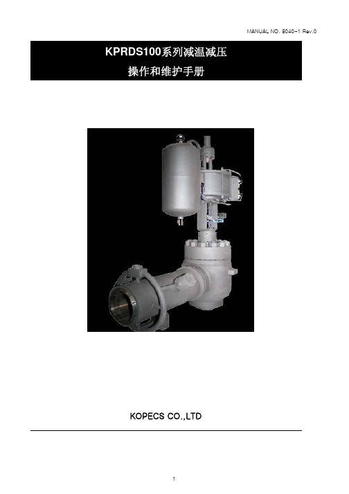
KOPECS CO.,LTD5. 维护这个部分是为日常维修人员做准备的,在进程之前每一个章节必须阅读和理解。
5. 1阀芯和阀座环首先,应该检查阀芯和阀座环的磨损和损坏情况如果有磨损和损坏的地方,维护的方法有重复操作、机器操作或更换新零件。
① Lapping :如果是轻微的损坏,重复操作是需要的。
注意:Caution: 在重复操作之前,必须确保阀芯和阀杆是好的,不要挤压和敲打阀座环这样会使阀座环扭曲变形从而导致无缘无故的泄露leakage.② 如果是过度的损坏,机器操作是需要的shall be required.注意:阀座阀芯和阀座环的表面均要在中心轴线的28%和30%的距离5. 2 阀座阀内件KPRDS100系列阀门的阀座阀芯和阀座环有一个备件拆下阀芯组合件和阀座环组合件然后就可以更换5. 3 填料填料函的维护是常规的有规律的维护的一种。
紧密的填料是填料挤压形成的. 填料法兰螺母和填料法兰均匀地上紧才形成了挤压必须小心不要过度的收紧以便阀门可以顺利的操作如果已经挤压到底了而且阀门还漏的话,就需要换新的填料。
按照下面的顺序:① 松开然后拆下填料法兰螺母② 沿着阀杆拿掉填料法兰和填料压盖③ 用适当的工具拆下填料④ 取适量的填料放在间隔环的上面和下面来更换填料⑤ 更换密封垫圈和填料法兰⑥ 更换并加紧填料螺栓螺母注意Caution : 不要过度加紧5. 4 平衡环平衡环是影响阀性能的最重要阀内件部件。
当阀定位器显示全关的时候,平衡环可以在阀芯和导向面之间阻止泄露。
拆卸阀内件的时候千万小心不要破坏它,如果密封圈有明显的破坏,那么必须换一个新的密封圈。
6. 阀体组装在完成必要的维护之后阀门必须按照下面的步骤重新组装:6. 1 典型的平衡环阀内件(参照图1或1-1)① 使所有的垫圈表面清洁② 安装阀座垫圈和阀座环③ 安装套筒.④ 当在套筒和导向套之间安装平衡环时,应该把平衡环安装在套筒的上方。
⑤ 安装上阀盖垫圈和导向套.⑥ 小心地安装阀杆和阀芯组件⑦ 在导向套的上方安装上阀盖垫圈⑧ 安装上阀盖和阀体的螺栓螺母,旋紧阀门的螺栓螺母。
普森斯 王字壳温湿度变送器说明书(WIFI型)
壁挂数码管王字壳温湿度变送器说明书(WIFI型)Ver2.0目录第1章产品简介 (3)1.1产品概述 (3)1.2功能特点 (3)1.3主要技术指标 (3)1.4产品选型 (4)1.5设备信息 (4)第2章设备安装及使用 (7)2.1设备安装说明 (7)2.2设备使用 (7)第3章监控平台介绍 (11)第4章常见问题及解决办法 (11)第5章注意事项 (11)第6章免责声明 (12)附录:部分探头尺寸 (13)第1章产品简介1.1产品概述该产品为壁挂高防护等级外壳,防护等级IP65,防雨雪且透气性好。
电路采用美国进口工业级微处理器芯片、进口高精度温度传感器,确保产品优异的可靠性、高精度和互换性。
可采集数据并通过WIFI方式上传到服务器。
本产品充分利用已架设好的WIFI通讯网络实现数据采集和传输,达到数据集中监控的目的。
可大大减少施工量,提高施工效率和维护成本。
设备7-30V宽压供电,外壳防护等级高,能适应现场各种恶劣条件。
1.2功能特点■采用瑞士进口的测量单元,测量精准■通过WIFI方式上传数据,支持局域网内通信、跨网关广域网通信■支持动态域名解析DNS■数据采集频率2s/次,数据上传频率1s~65535s/次可设■可接免费的云平台■产品采用壁挂式防水壳,安装方便,防护等级高。
1.3主要技术指标直流供电(默认)DC7-30V最大功耗0.1W(DC24V)A准精度湿度±2%RH(60%RH,25℃)温度±0.4℃(25℃)B准精度(默认)湿度±3%RH(60%RH,25℃)温度±0.5℃(25℃)变送器电路工作温湿度-40℃~+60℃,0%RH~95%RH(非结露)探头工作温度-40℃~+120℃默认:-40℃~+80℃探头工作湿度0%RH-100%RH温度显示分辨率0.1℃湿度显示分辨率0.1%RH温湿度刷新时间1s长期稳定性湿度≤1%RH/y温度≤0.1℃/y响应时间湿度≤8s(1m/s风速)温度≤25s(1m/s 风速)数据上传时间默认10s/次,1s~65535s 可设数据采集时间2s/次WIFI 通信参数802.11b/g/n安全性安全方式WEP/WPA-PSK/WPA2-PSK 加密类型WEP/TKIP/AES1.4产品选型1.5设备信息尺寸:PR-公司代号300SMG-壁挂数码管王字壳WS-温湿度变送、传感器WIFI-WIFI 型1外置铜头3外置西门子头4外置精装探头5外延精装探头6外延防水探头7外延高灵敏度探头9外延金属防水探头A 外延四分管螺纹探头B 外延宽温探头ZJ 外延夹持探头HD 活动螺纹探头FW蜂窝型探头(相比外延金属防水探头对湿度环境反应灵敏,不防尘,无法使用在粉尘较大的环境,抗2.5m/s 风)FF不锈钢防风探头(316L 不锈钢材质,耐腐蚀性强,高温强度优秀,间隙小,可抗30m/s 风,可阻挡细小粉尘穿透)数码管王字壳温湿度传感器外观图:1345679AB ZJ HD FWFF序名称内容号①设备贴膜上面带有产品logo以及名称②电源线DC5.5*2.1规格;使用配件电源适配器插入供电③传感器温湿度传感器④安装孔位使用配件膨胀螺丝包,将设备安装至墙面等需要安装的位置包装内容主设备×1产品合格证、保修卡×1膨胀螺丝包(含2个自攻螺丝及2个膨胀塞)×112V电源适配器×1第2章设备安装及使用2.1设备安装说明设备主体的安装2.2设备使用接通电源将电源适配器连接至设备的供电接口,再接通电源连接至网络1下载配置工具,使用QQ扫描二维码(仅限安卓手机),点击“客户端本地下载”,下载完成后根据手机提示将APP安装。
风电齿轮箱操作手册

1.5MW 风电齿轮箱操作维护手册大连重工·起重集团通用减速机厂目录1.用途与结构 22.辅助装置 33.性能参数 64.安装85.运行前的准备工作96.起动107.运行118.常见故障原因分析与处理方法139.维护1510.运输、储存1611.安全防护1712.易损件明细1813.附件1 润滑系统14.附件2 恒温开关15.附件3 电阻温度计16.附件4 加热器1.用途与结构该齿轮箱用于PWE1570/1577 型风力发电机,其用途是将风轮在风力作用下所产生的动力传递给发电机,并通过齿轮箱齿轮副的增速作用使输出轴的转速提高到发电机发电所需的转速。
齿轮箱由两级行星和一级平行轴传动以及辅助装置组成。
为了传动平稳和提高承载能力,齿轮采用斜齿并精密修形,外齿轮材料为渗碳合金钢,内齿轮为合金钢,一级行星架采用高合金铸钢材料,二级行星架和箱体采用高强度抗低温球墨铸铁。
主轴内置于增速机,与第一级行星架过盈连接。
齿轮箱通过弹性减震装置安装在主机架上。
齿轮箱的轴向空心孔用于安装控制回路电缆。
具体结构见图1。
图12 辅助装置2.1 润滑供油系统:润滑供油系统由泵-电机组、过滤器、阀及管路等组成,用于润滑系统所需的压力和流量,并控制系统的清洁度。
其工作原理见图2。
油泵上的安全阀设定压力为10bar,以防止压力过高损坏系统元件。
当润滑油温度低或当过滤器滤芯压差大于 4bar 时,滤芯上的单向阀打开,液压油只经过50μ的粗过滤;当温度逐渐升高,滤芯压差低于4bar 时,液压油经过10μ和50μ两级过滤。
无论何种情况,未经过滤的液压油决不允许进入齿轮箱内各润滑部位。
当油池温度低于30°C时,过滤器的压差发讯器报警信号无效;而当油池温度超过30°C时,当压差达到 3 bar 时,此时报警信号才有效,必须在两天内更换清洁的滤芯。
图22.2 风冷却器:用于冷却齿轮箱的润滑油。
该风冷却器由电机、高性能轴向风扇、散热片和温控阀、旁通阀组成。