vxworks653编程手册
VxWorks编程常用函数说明

三、IO 系统:ioLib.h 1、系统中的 IO 设备,包括键盘、串口、文件等,都用统一的接口访问。第一步通常先得到 文件描述符,然后进行读写或者设置的工作,最后关闭该描述符。 creat:建立文件 open:得到文件或设备的描述符 read:读文件或设备 write:写文件或设备 ioctl:设置参数 close:关闭文件描述符 remove:删除文件
二、常用的库: #i nclude "taskLib.h" /* 任务 */ #i nclude "msgQLib.h" /* 消息队列 */ #i nclude "semLib.h" /* 信号量 */ #i nclude "ioLib.h" /* IO */ #i nclude "wdLib.h" /* Watch dog */ #i nclude "logLib.h" /* 信息输出 */ #i nclude "socket.h" /* 网络套接字 */
taskSend() { int pd; /* pipe 的描述符 */ if ((pd = open("/pipe/mypipe", O_WRONLY, 0644)) == ERROR) { printf("Open pipe failed!"); } if (semTake(semMID, NO_WAIT) == ERROR) { printf("Pipe in use!"); } write(pd, "a", 1); semGive(semMID); close(pd); }
vxworks65编程手册
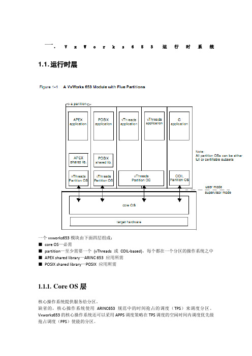
一. V x W o r k s653运行时系统1.1. 运行时层一个vxworks653模块由下面四层组成:■core OS—必需■partition—至少需要一个(vThreads 或COIL-based),每个都在一个分区的操作系统之中■APEX shared library—ARINC 653 应用所需■POSIX shared library—POSIX 应用所需1.1.1.Core OS层核心操作系统提供服务给分区。
缺省的,核心操作系统使用ARINC653规范中的时间抢占的调度(TPS)来调度分区。
Vxworks653的核心操作系统还可以采用APPS调度策略在TPS调度的空闲时间内调度优先级抢占调度(PPS)使能的分区。
核心操作系统提供给每个VThreads分区操作系统的服务包括:●分区系统资源●调度分区●代表分区的操作系统执行trap异常●定义和强制分区边界●装载分区●使用端口和通道在分区间传递消息●处理I/O●代表应用完成系统调用●支持分区的调试●监控分区和系统的健康1.1.2.vThreads 层vThreads分区操作系统在核心操作系统分配给该分区的时间内调度vThreads中的线程。
vThreads不直接与设备交互,而是通过核心操作系统的系统调用。
1.1.3.APEX 层构建在vThreads之上,遵循ARINC653规范,并且提供相应功能和API。
1.1.4.POSIX层构建在vThreads之上,遵循用于实时扩展的POSIX标准(1003.1b)。
1.2. 装载和启动当目标板加电时,按照下面的步骤进行装载和启动●初始的启动码装载核心操作系统,分区操作系统,共享库,以及应用●核心操作系统初始化自身,启动它自己的子系统●核心操作系统创建分区●核心操作系统启动分区调度器,并且让应用初始化自身核心操作系统可以在初始化完成之后下载在线装载的应用程序到分区。
应用可以在分区运行之时装载到分区。
VxWorks 驱动程序安装指南说明书
Document: CTI_SIO_Install Revision: 1.01Date: January 4, 2010 VxWorksDriver InstallationVxWorks Driver Installation1.H ISTORY (3)2.H ARDWARE R EQUIREMENTS (4)3.D RIVER F ILES (4)4.C ONFIGURATION (4)4.1. BSP Files (4)4.1.1. config.h (4)4.1.1.1. INCLUDE_CTI_U550 (4)4.1.1.2. INCLUDE_CTI_U650 (5)4.1.1.3. INCLUDE_CTI_U850 (5)4.1.1.4. INCLUDE_CTI_EXAR17XX5XPCI (5)4.1.1.5. CTI_PCI_MAXBOARDS (5)4.1.1.6. CTI_PCI_MAXCHANS (5)4.1.1.7. INCLUDE_CTI_AUTO485POLLER (5)4.1.1.8. CTI_DEFAULT_BAUD (6)4.1.1.9. CTI_AUTO485SWITCHBAUD (6)4.1.1.10. CTI_AUTO485POLLER_DELAY (6)4.1.1.11. CTI_SYS_PCI_INTCONNECT() (6)4.1.1.12. CTI_SYS_INTCONNECT() (6)4.1.1.13. CTI_SYS_INTENABLE() (7)4.1.1.14. CTI_SYS_IN_BYTE() (7)4.1.1.15. CTI_SYS_OUT_BYTE() (7)4.1.1.16. CTI_SYS_IN_WORD() (8)4.1.1.17. CTI_SYS_OUT_WORD() (8)4.1.1.18. CTI_SYS_IN_LONG() (8)4.1.1.19. CTI_SYS_OUT_LONG() (9)4.1.2. sysLib.c (9)4.1.2.1. sysHwInit() (9)4.1.2.2. sysHwInit2() (10)4.2. Driver Files (10)4.2.1. sysCTISerial.c (10)4.2.1.1. Storage (10)4.2.1.2. Configuration (11)4.2.1.3. Interrupts (12)4.2.1.4. Enumeration (13)4.3. Tornado Projects (14)4.3.1. Connect Tech Inc. SIO (14)4.3.2. Use alternate base name (14)5.E XAMPLES (14)5.1. pcP3CTI_1 (14)5.2. pcP3CTI_2 (14)5.3. pcP3CTI_3 (15)6.I NSTALLATION C HECKLIST (16)1. HistoryOriginal draft.Added installation checklist.Added 3rd sample BSP.Fixed minor mistakes.Adapted for both Tornado and Workbench builds.2. Hardware RequirementsThis driver supports the following products:Xtreme/104 switchableXtreme/104 232BlueStorm/LPXtreme/104-Plus3. Driver FilesCopy the following files into your BSP directory (<WIND_INST>\target\config\<BSP_NAME>):00cti.cdfctiSio.cctiSio.hsysCTISerial.cusrCTISerial.c4. Configuration4.1. BSP FilesThe following files should be modified to support the CTI SIO driver. These modifications can be done in any other way as appropriate, but the following are suggestions made based on the Pentium III BSP. For sample modified files, refer to the files (of the same name) located within the driver distribution package. Sample files are from the Pentium III BSP. Note; file names and locations of information may differ in your BSP.<WIND_INST>\target\config\<BSP_NAME>\config.h<WIND_INST>\target\config\<BSP_NAME>\sysLib.cThe sample files included with the driver package should not be copied over any files in your BSP. These sample files are included only so that you can see the required changes in the context of complete files.4.1.1.config.hAdd a section to your config.h file so that there is a place for the driver options. If your config.h has an “if-def” block used to determine when to define INCLUDE_PCI, it is advised that you place this new section above that “if-def” block. This suggestion is made so that the “if-def” section can be modified to define INCLUDE_PCI when needed by any included CTI boards. The section for CTI driver configuration should surrounded by a check forINCLUDE_CTI_SIO being defined.For example:/* Connect Tech Inc. serial driver options */#if defined(INCLUDE_CTI_SIO)#define INCLUDE_CTI_U550/* support for 550 UARTs */#endif/* defined(INCLUDE_CTI_SIO) */A complete list of the available configuration options follows:4.1.1.1.INCLUDE_CTI_U550Define INCLUDE_CTI_U550 to include support for Xtreme/104 products that utilize 550 UARTs. This can be determined by examining the UART chips on the Xtreme/104 board itself, or by contacting CTI support staff.Usage:#define INCLUDE_CTI_U5504.1.1.2.INCLUDE_CTI_U650Define INCLUDE_CTI_U650 to include support for Xtreme/104 products that utilize 650 UARTs. This can be determined by examining the UART chips on the Xtreme/104 board itself, or by contacting CTI support staff.Usage:#define INCLUDE_CTI_U6504.1.1.3.INCLUDE_CTI_U850Define INCLUDE_CTI_U850 to include support for Xtreme/104 products that utilize 850 UARTs. This can be determined by examining the UART chips on the Xtreme/104 board itself, or by contacting CTI support staff.Usage:#define INCLUDE_CTI_U8504.1.1.4.INCLUDE_CTI_EXAR17XX5XPCIDefine INCLUDE_CTI_EXAR17XX5XPCI to include support for BlueStorm/LP and Xtreme/104-Plus products. You should also include you BSP’s PCI support if these pr oducts are to be used.Usage:#define INCLUDE_CTI_EXAR17XX5XPCI4.1.1.5.CTI_PCI_MAXBOARDSCTI_PCI_MAXBOARDS is used to define the maximum number of CTI PCI boards that can be enumerated. If not defined the default is 1.Usage:#define CTI_PCI_MAXBOARDS X/* where X is the maximum number of boards */4.1.1.6.CTI_PCI_MAXCHANSCTI_PCI_MAXCHANS is used to define the maximum number of serial channels that can be used by enumerated CTI PCI devices. This number is not the maximum per CTI PCI device, it is the maximum total number of channels across all CTI PCI devices. If not defined the default is 8.Usage:#define CTI_PCI_MAXCHANS X/* where X is the maximum number of channels */4.1.1.7.INCLUDE_CTI_AUTO485POLLERWhen using half-duplex RS485, the receiver and transmitter need to be toggled on and off depending on whether data is being sent or received. On CTI products that do not utilize UARTs with the capability to do this automatically, the driver must perform the toggling.This can be done in one of two ways; Using the interrupt service routine (ISR) of thechannel; Using a watchdog timer as a poller. In order to use the watchdog timerINCLUDE_CTI_AUTO485POLLER must be defined.Usage:#define INCLUDE_CTI_AUTO485POLLER4.1.1.8.CTI_DEFAULT_BAUDCTI_DEFAULT_BAUD is used to define the default baud rate when the serial channels are initialized. If not defined the default is 9600.Usage:#define CTI_DEFAULT_BAUD X/* where X is the default baud rate in bps */4.1.1.9.CTI_AUTO485SWITCHBAUDWhen using the CTIAUTO485SWITCHED auto 485 direction control method,CTI_AUTO485SWITCHBAUD defines the baud rate used to switch between ISR and poller methods. When the baud rate is less than CTI_AUTO485SWITCHBAUD the ISR method is used, else the poller method is used. If not defined the default is 9600.Usage:#define CTI_AUTO485SWITCHBAUD X/* where X is the baud rate in bps */4.1.1.10.CTI_AUTO485POLLER_DELAYWhen the poller auto 485 direction control method is being used a watchdog timerperforms a polling operation to look for the end of a transmit. This watchdog timer is set to expire every CTI_AUTO485POLLER_DELAY ticks. If not defined the default is 1.Usage:#define CTI_AUTO485POLLER_DELAY X/* where X is the delay in ticks */4.1.1.11.CTI_SYS_PCI_INTCONNECT()The CTI_SYS_PCI_INTCONNECT() macro is used to connect a PCI device interrupt to an interrupt service routine. The default definition of this macro uses pciIntConnect().Usage:/** _intLevel_ - interrupt level to connect _isr_ to* _isr_ - interrupt service routine to connect to _intLevel_* _arg_ - argument to be passed to _isr_* _result_ - STATUS result of the macro*/#define CTI_SYS_PCI_INTCONNECT(_intLevel_, _isr_, _arg_, _result_) \{ \/* place desired code here */ \}4.1.1.12.CTI_SYS_INTCONNECT()The CTI_SYS_INTCONNECT() macro is used to connect a device interrupt to an interrupt service routine. The default definition of this macro uses intConnect().Usage:/** _intLevel_ - interrupt level to connect _isr_ to* _isr_ - interrupt service routine to connect to _intLevel_* _arg_ - argument to be passed to _isr_* _result_ - STATUS result of the macro*/#define CTI_SYS_INTCONNECT(_intLevel_, _isr_, _arg_, _result_) \{ \/* place desired code here */ \}4.1.1.13.CTI_SYS_INTENABLE()The CTI_SYS_INTENABLE() macro is used to enable an interrupt level. The defaultdefinition of this macro uses sysIntEnablePIC().Usage:/** _intLevel_ - interrupt level to enable* _result_ - STATUS result of the macro*/#define CTI_SYS_INTENABLE(_intLevel_, _result_) \{ \/* place desired code here */ \}4.1.1.14.CTI_SYS_IN_BYTE()The CTI_SYS_IN_BYTE() macro is used to read an 8 bit value. The default definition of this macro uses sysInByte() for port I/O and does a direct assignment for memory I/O.Usage:/** _ioMode_ - I/O mode (CTIIOPORT or CTIIOMEM)* _address_ - address to read from* _value_ - receives 8 bit value read from _address_*/#define CTI_SYS_IN_BYTE(_ioMode_, _address_, _value_) \{ \if((_ioMode_) == CTIIOPORT) { \/* place port I/O code here */ \} \else { \/* place memory I/O code here */ \} \}4.1.1.15.CTI_SYS_OUT_BYTE()The CTI_SYS_OUT_BYTE() macro is used to write an 8 bit value. The default definition of this macro uses sysOutByte() for port I/O and does a direct assignment for memory I/O.Usage:/** _ioMode_ - I/O mode (CTIIOPORT or CTIIOMEM)* _address_ - address to write to* _value_ - 8 bit value to write to _address_*/#define CTI_SYS_OUT_BYTE(_ioMode_, _address_, _value_) \{ \if((_ioMode_) == CTIIOPORT) { \/* place port I/O code here */ \} \else { \/* place memory I/O code here */ \} \}4.1.1.16.CTI_SYS_IN_WORD()The CTI_SYS_IN_WORD() macro is used to read a 16 bit value. The default definition of this macro uses sysInWord() for port I/O and does a direct assignment for memory I/O.Usage:/** _ioMode_ - I/O mode (CTIIOPORT or CTIIOMEM)* _address_ - address to read from* _value_ - receives 16 bit value read from _address_*/#define CTI_SYS_IN_WORD(_ioMode_, _address_, _value_) \{ \if((_ioMode_) == CTIIOPORT) { \/* place port I/O code here */ \} \else { \/* place memory I/O code here */ \} \}4.1.1.17.CTI_SYS_OUT_WORD()The CTI_SYS_OUT_WORD() macro is used to write a 16 bit value. The default definition of this macro uses sysOutWord() for port I/O and does a direct assignment for memory I/O.Usage:/** _ioMode_ - I/O mode (CTIIOPORT or CTIIOMEM)* _address_ - address to write to* _value_ - 16 bit value to write to _address_*/#define CTI_SYS_OUT_WORD(_ioMode_, _address_, _value_) \{ \if((_ioMode_) == CTIIOPORT) { \/* place port I/O code here */ \} \else { \/* place memory I/O code here */ \} \}4.1.1.18.CTI_SYS_IN_LONG()The CTI_SYS_IN_LONG() macro is used to read a 32 bit value. The default definition of this macro uses sysInLong() for port I/O and does a direct assignment for memory I/O.Usage:/** _ioMode_ - I/O mode (CTIIOPORT or CTIIOMEM)* _address_ - address to read from* _value_ - receives 32 bit value read from _address_*/#define CTI_SYS_IN_BYTE(_ioMode_, _address_, _value_) \{ \if((_ioMode_) == CTIIOPORT) { \/* place port I/O code here */ \} \else { \/* place memory I/O code here */ \} \}4.1.1.19.CTI_SYS_OUT_LONG()The CTI_SYS_OUT_LONG() macro is used to write a 32 bit value. The default definition of this macro uses sysOutLong() for port I/O and does a direct assignment for memory I/O.Usage:/** _ioMode_ - I/O mode (CTIIOPORT or CTIIOMEM)* _address_ - address to write to* _value_ - 32 bit value to write to _address_*/#define CTI_SYS_OUT_LONG(_ioMode_, _address_, _value_) \{ \if((_ioMode_) == CTIIOPORT) { \/* place port I/O code here */ \} \else { \/* place memory I/O code here */ \} \}4.1.2.sysLib.cAdd a section to your sysLib.c file that includes the file sysCTISerial.c. This file includes the CTI SIO driver and defines routines used to configure the CTI serial channels. This section should come after the PCI configuration files have been included and should be surrounded by a check for INCLUDE_CTI_SIO being defined.For example:#if defined(INCLUDE_CTI_SIO)#include "sysCTISerial.c"#endif/* defined(INCLUDE_CTI_SIO) */In addition to including the driver and driver configuration routines, the routines sysHwInit() and sysHwInit2() need to be modified to call the serial configuration routines defined in sysCTISerial.c.4.1.2.1.sysHwInit()During sysHwInit(), sysCTISerialHwInit() should be called to initially configure the CTIserial channels. This call should be made after any PCI initialization in order for CTI PCI adapters to be configured.For example:#if defined(INCLUDE_CTI_SIO)sysCTISerialHwInit();#endif/* defined(INCLUDE_CTI_SIO) */4.1.2.2.sysHwInit2()During sysHwInit2(), sysCTISerialHwInit2() should be called to connect and enableinterrupts used by the CTI serial channels.For example:#if defined(INCLUDE_CTI_SIO)sysCTISerialHwInit2();#endif/* defined(INCLUDE_CTI_SIO) */4.2. Driver FilesThe file sysCTISerial.c, which is included into sysLib.c, needs to be configured to properly match the setup of your system.4.2.1.sysCTISerial.csysCTISerial.c contains rountines used to configure any CTI serial adapters you have. The configuration includes:storage for board and channel structuresboard/channel configuration and initializationinterrupt connecting and enablingchannel enumerationThe code in this section is only meant to serve as a short example. For a more complete sample refer to the sample BSP’s provided with the driver files. For a description of routine parameters refer to the documentation for that routine.4.2.1.1.StorageEach board and channel must have a corresponding structure allocated for it. This istypically done by declaring local variables in the file sysCTISerial.c.Typically one board structure (CTI_BOARD) is defined for each non-PCI CTI adapter.For example:LOCAL CTI_BOARD ctiXt1Board;LOCAL CTI_BOARD ctiXt2Board;For each of the non-PCI adapters, an array of channel structures should be defined aswell. The size of these arrays depends on the number of channels supported by theadapters.For example:LOCAL CTI_CHAN ctiXt1Chans[8];LOCAL CTI_CHAN ctiXt2Chans[4];For PCI adapters, only one instance of CTI_PCI_DEVICESET need be defined. The maximum number of supported adapters and channels should be defined with CTI_PCI_MAXBOARDS and CTI_PCI_MAXCHANS (see section 4.1.1 - config.h for more information onCTI_PCI_MAXBOARDS and CTI_PCI_MAXCHANS).For example:#if defined(INCLUDE_PCI)LOCAL CTI_PCI_DEVICESET ctiPciDevset;#endif/* defined(INCLUDE_PCI) */4.2.1.2.ConfigurationDuring sysHwInit() sysCTISerialHwInit() should be called. This is where the board andchannels structures declared in the previous section are configured and initialized.Each non-PCI board structure should be configured using ctiBoardConfig() and initialized using ctiBoardHrdInit().PCI adapters should be enumerated and initialized using ctiPciConfig() and ctiPciHrdInit().For example:void sysCTISerialHwInit(void){if(OK == ctiBoardConfig(&ctiXt1Board,CTIU650,CTIIOPORT,0x300,0x340, /* 0 if status port not being used */0x05,7372800,4, /* 1 if using extended baud rates */ctiXt1Chans,8,NULL,NULL,0xFF)){if(sysBp) {ctiBoardHrdInit(&ctiXt1Board);}}if(OK == ctiBoardConfig(&ctiXt2Board,CTIU850,CTIIOPORT,0x200,0x240, /* 0 if status port not being used */0x0A,7372800,4, /* 1 if using extended baud rates */ctiXt2Chans,4,NULL,NULL,0xF)){if(sysBp) {ctiBoardHrdInit(&ctiXt2Board);}}#if defined(INCLUDE_PCI)if(OK == ctiPciConfig(&ctiPciDevset, NULL, NULL)) {if(sysBp) {ctiPciHrdInit(&ctiPciDevset);}}#endif/* defined(INCLUDE_PCI) */}4.2.1.3.InterruptssysCTISerialHwInit2() should be called during sysHwInit2() and is responsible for connecting and enabling interrupts used by the CTI adapters.The operations of connecting an interrupt to an interrupt service routine as well asenabling the interrupt have been encapsulated into driver rountines ctiBoardIntConnect() and ctiPciIntConnect(). The behaviour of these routines is controlled by the macrosCTI_SYS_INTCONNECT(), CTI_SYS_PCI_INTCONNECT(), and CTI_SYS_INTENABLE(). These macros can be redefined from their default behaviour. See section 4.1.1 - config.h formore information on CTI_SYS_INTCONNECT(), CTI_SYS_PCI_INTCONNECT(), andCTI_SYS_INTENABLE(). These routines do not have to be used and in some cases may not be sufficient. The specifics of their operation can be seen in ctiSio.c.For example:void sysCTISerialHwInit2(void){ctiBoardIntConnect(&ctiXt1Board);ctiBoardIntConnect(&ctiXt2Board);#if defined(INCLUDE_PCI)ctiPciIntConnect(&ctiPciDevset);#endif/* defined(INCLUDE_PCI) */}4.2.1.4.EnumerationEach serial channel must be associated with a device. The CTI serial channels areenumerated using sysCTISerialChanGet(). This routine takes an index value specifyingwhich channel structure to retrieve, and effectively acts as a look-up table for thechannels. The order in which the channels are returned determines the order in which the channels are associated with device names.For example:SIO_CHAN* sysCTISerialChanGet(int channel/* serial channel */){if((channel >= 0) && (channel < 8)) {return((SIO_CHAN*)&ctiXt1Chans[channel]);}else if((channel >= 8) && (channel < (8 + 4))) {return((SIO_CHAN*)&ctiXt2Chans[channel - 8]);}#if defined(INCLUDE_PCI)else if((channel >= (8 + 4)) &&(channel < (8 + 4 + hans))){return((SIO_CHAN*)&(ctiPciDevset.pChans[channel - 8 - 4]));}#endif/* defined(INCLUDE_PCI) */return((SIO_CHAN*)ERROR);}The total number of channels needs to be reported using sysCTISerialGetNumChans(). This routine simply needs to return the total number of channels being used across all CTIadapters.For example:UINT16sysCTISerialGetNumChans(void){UINT16retVal = 0;retVal += 8;retVal += 4;#if defined(INCLUDE_PCI)retVal += hans;#endif/* defined(INCLUDE_PCI) */return(retVal);}4.3. Tornado/WorkBench ProjectsBootable VxWorks image projects based on a BSP containing the CTI driver files will have a new folder available under hardware\peripherals\serial called “Connect Tech Inc.”. This folder contains components for controlling the CTI serial driver. A description of the components follows:4.3.1.Connect Tech Inc. SIOThis component controls INCLUDE_CTI_SIO (used earlier when including the CTI serial driver in the BSP).e alternate base nameIf this component is not included, the CTI serial channels will be named “/tyCo/X” where X is the channel index value and is based on the defined NUM_TTY value so that the names do not collide with other serial devices. However, it may be desireable to use a different base name. By including the Use alternate base name component, the default behaviour is to name the CTI serial channels “/tyCTI/X” where X is the channel index value starting at 0.The Use alternate base name component has a parameter called CTI_TY_NAME_BASE which can be used to set a base name other than “/tyCTI/”.5. ExamplesIncluded with the driver files are three example BSP’s. These example BSP’s are based on the Pentium III BSP from WindRiver. A description of each of the example BSP’s follows:5.1. pcP3CTI_1This example is based on the following CTI serial adapters:Xtreme/104 RS-2328 channels.Base I/O address is 0x300.IRQ is 10.Status port is in use.Extended baud rates not in use.BlueStorm/LP RS-2324 channels.5.2. pcP3CTI_2This example is based on the following CTI serial adapters:Xtreme/104 14 RS-232 channels.Base I/O address is 0x300.IRQ is 10.Status port is in use.Extended baud rates not in use.Xtreme/104 28 channels.Base I/O address is 0x200.Channels 1, 3, 5, and 7 are on IRQ 5, channels 2, 4, 6, and 8 are on IRQ 9. SeeMode 2 in the Interrupt Selection section of the Xtreme/104 manual.Status port is not in use.Extended baud rates in use.Channels 1 and 2 are RS-232, channels 3, 4, and 5 are RS-485 full-duplex,channels 6, 7, and 8 are RS-485 half-duplex.Xtreme/104-Plus Switchable4 channels.Channels 1 and 2 are RS-485 full-duplex, channels 3 and 4 are RS-232.5.3. pcP3CTI_3This example is based on the following CTI serial adapters:BlueStorm/LP8 RS-232 channels.6. Installation Checklist。
基于VxWorks653的仿真飞行管理系统设计与实现

ti pprh eal ecit no to f acl iei ranvgt nRN V i mae u. hs ae, ed t e dsr i f hdo l ua v Ae aia o( A )s kdot t id po me c t n i
【 ywod l h nae n ytm; x rs6 3 N v ai C m nct n R AV Ke r sFi t J s Ma gmet s S e V Wok 5 ; ai t n;o mu i i ; N g o ao
21 0 1年
第1 3期
S INC C E E&T C O O F MA I N E HN L GYI OR T O N
o科教前 台0
科技信息
基于 V Wok 5 x rs 3的仿真飞行管理 6 系统设计与实现
杨 (. 1中国电子 科技 集团公 司 第二十研 究 所 明 ’ 李 斌 ’ 姚 迪 2 , 3 陕西 西安 7 0 6 2 中国 人 民解 放军 空军 工程大 学工 程学 院 1 0 8; .
计。
【 键 词 】 行 管理 系统 ; x  ̄s 5 ; 关 飞 V Wo 3 导航 ; 信 ; 6 通 区域 导 航
.
【 src] hs pp repa s te V W0k 6 3 S rme ok, d d e eerh w r 南r te srcue n e urm n o l h Abta tT i ae xli h x rs 5 ’ a w rs os a rsac ok n f n a h t tr u ad rq i et f Fi t e r g
程 度 , 轻 驾 驶 员 的 工作 负 担 , 来 巨 大 的 无 可 估 量 的 经 济效 益 。 减 带
VxWorks 网络编程教程

1. 2. 3. 4. 5. 6. 7. 8. 9. 10. fei2=muxDevLoad(0,fei82557EndLoad,"1:0x00:0x20:0x20:0x00",1,0) muxDevStart(fei2) ipAttach(0,"fei") ifMaskSet("fei0",0xffffff00) ifAddrSet("fei0","136.12.117.10") hostAdd("woof-route-10","136.12.117.10") muxShow hostShow ifShow mRouteShow
7
北京邮电大学培训中心
8
ULIP网卡的路由使能
连接到VxSim目标系统
北京邮电大学培训中心
9
北京邮电大学培训中心
10
TFTP示例演示
• 主机到主机的数据传送
192.18.22.13
35
209.134.16.123
36
北京邮电大学培训中心
北京邮电大学培训中心
传输协议(Transport Protocols)
TFTP Server TFTP Client
2. VxWorks网络概述
• 网络上的设备需要以某种标准交互数据 • IP协议套件提供了系统独立的协议 • VxWorks基于BSD4.4 release提供了TCP/IP 协议的实现 • 包括以下特性:
– 增强的可配置和可伸缩性 – MUX层 – 支持其他兼容的Internet特性
3
北京邮电大学培训中心
4
VxWorks开发教程

任务删除
使用`taskDelete()`函数删除 指定任务,释放任务所占用的
资源。
任务状态转换
通过`taskSuspend()`和 `taskResume()`函数实现任务
的挂起与恢复,通过 `taskDelay()`函数实现任务延
时。
任务优先级调度策略
优先级抢占式调度
01
高优先级任务可抢占低优先级任务的执行,确保关键任务得到
TCP/IP通信实例分析
通过分析一个简单的基于TCP/IP协议栈的通信实例,加深对网络通信编程的理解和掌握。
无线通信模块集成与调试经验分享
01
02
无线通信模块概述
介绍常见的无线通信模块类型及其特点, 如Wi-Fi模块、蓝牙模块、ZigBee模块 等。
模块集成步骤与注意 事项
详细讲解无线通信模块与VxWorks系 统的集成步骤,包括硬件连接、驱动程 序开发、协议栈配置等,并分享一些实 用的调试技巧和经验。
套接字编程基本流程
包括创建套接字、绑定地址、监听连接、接受连接、发送和接收数据等步骤。
基于TCP/IP协议栈网络通信实现
TCP/IP协议栈概述
介绍TCP/IP协议栈的基本概念和层次结构,以及各层的主要功能和协议。
网络通信编程接口
讲解VxWorks提供的网络通信编程接口,如socket()、bind()、listen()、accept()、send()、recv()等函数 的使用方法和注意事项。
中断控制器识别中断源,并将其传递 给CPU。
中断类型及响应过程
3. 中断处理
CPU保存当前执行上下文,跳转到中 断处理程序执行。
4. 中断返回
中断处理程序执行完毕后,CPU恢复保 存的上下文并继续执行原程序。
VxWorks编程指导

Wind River哲学是利用两个相互协作的操作系统来互相补充对方的不足(譬如VxWorks和Windows 或 VxWorks和Unix),让他们各尽所长。VxWorks为应用提供实时性,而主机被用来进行应用开发和运行非实时的应用程序。
VxWorks是可以裁剪的,你可以将VxWorks裁剪为只包含你的应用所需要的部件。在开发期间为了方便你的开发,你可以加入网络部件,当发行最终版本时为了节约资源你可以轻松的去掉网络部件。
dosFs为面向文件的设备驱动程序提供的服务在dosFsLib里实现。
1.3.2. RT-11兼容文件系统rt11Fs
rt11Fs文件系统兼容于RT-11操作系统。该文件系统一直被实时应用使用,因为该文件系统下的所有文件都是连续存储的。但是它缺少树状文件组织结构,树状文件组织结构对大容量磁盘是特别有用的。同时,呆板的连续存储空间分配会导致大量的磁盘碎片。所以,dosFs要优于rt11Fs。
1.3.5. CDROM文件系统
VxWorks为了让应用读写按照ISO9660文件系统标准格式化的CDROM设备提供了cdRomFs。初始化cdRomFs文件系统后,挂接cdRomFs到一个CDROM设备,就可以用POSIX标准的I/O调用来读CDROM。
1.3.6. 可替换的文件系统
POSIX接口包括:
m 异步I/O
m 信号量
m 消息对列
m 内存管理
m 信号
m 调度
m 时钟
1.2. I/O系统
VxWorks的I/O系统对多种输入输出设备提供统一的存取机制。既可以调用基本的I/O函数:creat(),remove(),open(),close( ),read(),write(),和ioctl();也可以调用高层I/O函数,譬如printf(),scanf()。
VxWorks开发教程

错误定位与排查方法
介绍针对不同类型的错误,如何采用有效的定位与排 查方法,如查看日志文件、使用调试器等。
问题解决经验分享
分享在解决VxWorks开发过程中遇到问题的 经验和技巧,帮助开发人员快速解决问题并避 免类似问题的再次出现。
THANK YOU
感谢聆听
消息队列是一种进程间通信机制,允许任务 之间发送和接收消息。
管道
管道是一种半双工的进程间通信机制,允许 任务之间以流的方式传输数据。
共享内存
共享内存允许多个任务访问同一块内存空间, 需要进行同步以避免数据冲突。
04
VxWorks驱动程序开发
设备驱动模型及框架介绍
80%
设备驱动模型
VxWorks采用层次化的设备驱动 模型,包括设备驱动管理层、设备 驱动服务层和硬件抽象层。
VxWorks开发教程
目
CONTENCT
录
• VxWorks概述 • VxWorks开发环境搭建 • VxWorks内核机制解析 • VxWorks驱动程序开发 • VxWorks网络编程技术探讨 • VxWorks图形界面设计实践 • VxWorks调试与优化技巧分享
01
VxWorks概述
VxWorks定义与特点
02
优化算法选择
03
系统资源调优
探讨针对不同性能问题的优化算 法选择,包括时间复杂度优化、 空间复杂度优化等。
提供系统资源调优的建议,如合 理分配内存、优化任务调度等, 以提高程序运行效率。
常见问题排查思路总结
常见错误类型分析
总结在VxWorks开发过程中常见的错误类型, 如编译错误、链接错误、运行时错误等,并分 析其产生原因。
中断优先级
- 1、下载文档前请自行甄别文档内容的完整性,平台不提供额外的编辑、内容补充、找答案等附加服务。
- 2、"仅部分预览"的文档,不可在线预览部分如存在完整性等问题,可反馈申请退款(可完整预览的文档不适用该条件!)。
- 3、如文档侵犯您的权益,请联系客服反馈,我们会尽快为您处理(人工客服工作时间:9:00-18:30)。
一.V xWorks653运行时系统1.1. 运行时层一个vxworks653模块由下面四层组成:■core OS—必需■partition—至少需要一个(vThreads 或COIL-based),每个都在一个分区的操作系统之中■APEX shared library—ARINC 653 应用所需■POSIX shared library—POSIX 应用所需1.1.1.Core OS层核心操作系统提供服务给分区。
缺省的,核心操作系统使用ARINC653规范中的时间抢占的调度(TPS)来调度分区。
Vxworks653的核心操作系统还可以采用APPS调度策略在TPS调度的空闲时间内调度优先级抢占调度(PPS)使能的分区。
核心操作系统提供给每个VThreads分区操作系统的服务包括:●分区系统资源●调度分区●代表分区的操作系统执行trap异常●定义和强制分区边界●装载分区●使用端口和通道在分区间传递消息●处理I/O●代表应用完成系统调用●支持分区的调试●监控分区和系统的健康1.1.2.vThreads 层vThreads分区操作系统在核心操作系统分配给该分区的时间内调度vThreads中的线程。
vThreads不直接与设备交互,而是通过核心操作系统的系统调用。
1.1.3.APEX 层构建在vThreads之上,遵循ARINC653规范,并且提供相应功能和API。
1.1.4.POSIX层构建在vThreads之上,遵循用于实时扩展的POSIX标准(1003.1b)。
1.2. 装载和启动当目标板加电时,按照下面的步骤进行装载和启动●初始的启动码装载核心操作系统,分区操作系统,共享库,以及应用●核心操作系统初始化自身,启动它自己的子系统●核心操作系统创建分区●核心操作系统启动分区调度器,并且让应用初始化自身核心操作系统可以在初始化完成之后下载在线装载的应用程序到分区。
应用可以在分区运行之时装载到分区。
1.3. 运行时模型核心操作系统处理来自每个分区的系统调用,并且在运行系统调用前校验每个系统调用的语句。
使用vThreads分区操作系统的应用拥有完全的vThreads任务间通信机制。
APEX库提供了遵循ARINC653规范的分区管理,进程管理以及时间管理;为分区间通信提供了消息,通道,端口;为分区内通信提供缓冲区,黑板,信号量以及事件。
端口映射允许在VxWorks653模块之外通信。
二.开发APEX应用APEX是位于应用程序和支持ARINC653规范的操作系统之间的API。
对于VxWorks653,操作系统是vThreads分区操作系统和核心操作系统。
APEX给vThreads分区提供了时间、进程管理以及管理周期性和非周期性进程的能力。
APEX提供如下服务:●管理分区●管理进程●管理时间●与其他分区通信(使用消息,端口和通道)●分区内的通信(使用缓冲区,黑板,信号量以及事件)●监控健康2.1. 分区管理分区的管理包含分配分区内存以及依据ARINC653规范初始化分区。
2.1.1.分配分区内存每个分区的资源分配都定义在基于XML的配置和编译过程中,根据指定在该规范中的分区需求,为每个分区分配唯一的物理内存。
通过禁止对超过该分区的内存区域的写访问来确保内存分区。
2.1.2.初始化分区:冷和热启动冷启动:当VxWorks653模块加电并且创建分区时,使用冷启动分区操作模式。
在冷启动模式下,分区对象被分配并且初始化。
热启动:热启动分区操作模式导致一个分区重新初始化或者由于遇到错误重新启动。
在热启动模式下,持久数据不会重新初始化,分区代码也不会重新装载。
每个分区所使用的资源(如通道、进程、队列、信号量或事件等)在系统编译时指定。
在分区的初始化阶段,创建分区所需的资源,然后分区进入NORMAL模式。
2.1.3.分区属性分区属性定义在XML配置文件中。
固定的分区属性包括:●标识符:定义在VxWorks653模块上唯一的分区标识符。
●内存需求:分配给分区的物理内存●周期:分区的激活周期。
用来确定核心操作系统的整个时间帧内的分区激活的运行时位置。
●持续时间:分区的每个周期内核心操作系统给予的处理器时间。
●关键级别:分区的RTCA/DO-178B认证级别。
●通信需求:分区与其他分区通信的通信通道●分区健康监控表(健康监控配置):健康监控器对于故障的动作指令。
2.1.4.获得分区状态GET_PARTITION_STATUS函数可以获得当前情况下的分区状态。
type PARTITION_STATUS_TYPE is recordIDENTIFIER : PARTITION_ID_TYPE;PERIOD : SYSTEM_TIME_TYPE;DURATION : SYSTEM_TIME_TYPE;LOCK_LEVEL : LOCK_LEVEL_TYPE;OPERATING_MODE : OPERATING_MODE_TYPE;START_CONDITION : START_CONDITION_TYPE;end record;type OPERATING_MODE_TYPE is (IDLE, COLD_START, WARM_START, NORMAL);type START_CONDITION_TYPE is (NORMAL_START,PARTITION_RESTART,HM_MODULE_RESTART,HM_PARTITION_RESTART);Where:NORMAL_START is a normal power-up.PARTITION_RESTART is either due to COLD_START or WARM_START by the partitionitself, through the SET_PARTITION_MODE service.HM_MODULE_RESTART is a recovery action taken at module level by the HM.HM_PARTITION_RESTART is a recovery action taken at partition level by the HM.2.1.5.设置分区模式SET_PARTITION_MODE函数可以设置分区模式为IDLE,COLD_START,WARM_START,NORMAL。
其中IDLE模式:分区关闭。
分区未被初始化,没有进程正在运行,但是分配给该分区的时间窗口未被改变。
COLD_START模式:分区重启使用冷启动初始化。
WARM_START模式:分区重启使用热启动初始化。
NORMAL模式:激活的进程被调度。
2.1.6.控制分区中的抢占进程的LOCK_PREEMPTION函数可以为分区中的抢占上锁。
该函数增加了分区的锁级,使得进程不能在分区中重调度。
当进程访问临界区时,或资源被同一分区中的多个进程共享时,这个能力十分重要。
LOCK_PREEMPTION函数不会影响其他分区的调度。
如果一个位于临界区的进程由于分区窗口结束而被中断时,当分区再次运行时仍然是该进程最先运行。
UNLOCK_PREEMPTION函数可以解锁分区的抢占。
这个函数降低了分区的锁级,仅当锁级达到零时,进程的重调度才能恢复。
2.1.7.分区调度对于时间分区,ARINC653提供了两级调度机制。
在核心模块级,采用预先确定的基于时间窗的循环调度算法来调度各个分区,分区没有优先级。
核心操作系统根据每个分区的周期与持续时间信息,维护一个固定时间长度的主时间帧,该主时间帧的时间长度为所有分区周期的最小公倍数。
静态调度算法为每个分区生成该主时间帧内相应的分区调度窗口,每个分区调度窗口由从主时间帧开始的偏移和期待的持续时间来定义。
分区的调度窗口事先定义在配置表中。
每个分区在其分区调度窗口内被激活并占用CPU,并保证每个分区在其调度窗口内运行时不被其他分区打断。
主时间帧在模块的运行期内周期性的重复,每个主时间帧中拥有相同的分区调度窗口执行次序。
2.2. 进程管理APEX进程是包含在APEX分区内的编程单元。
同一分区内的进程可以并发执行。
进程由可执行程序、数据和栈、程序计数器、栈指针以及优先级期限组成。
进程管理包含创建进程、改变进程当前优先级、得到进程的当前状态、得到进程ID、挂起和恢复进程、停止和启动进程、控制抢占等函数。
2.2.1.进程类型●周期性进程●非周期性进程2.2.2.进程调度在分区级,调度单元是APEX进程。
每个进程拥有优先级,调度算法是优先级抢占的。
分区级操作系统总是选择处于就绪状态且具有最高优先级的进程获得处理器资源。
如果多个进程拥有相同的优先级,则分区操作系统选择就绪队列中第一个进程。
进程将控制处理器资源直到另一个进程重调度事件发生。
2.2.3.进程状态变迁2.3. 时间管理2.3.1.调度分区见2.1.7分区调度2.3.2.系统时钟时间系统时钟时间为系统提供了唯一的时间。
GET_TIME函数可以获得系统时钟时间。
2.3.3.请求资源和超时当进程请求一个APEX资源(例如信号量或事件)时,可以指定下列超时类型之一:●INFINITE_TIME_VALUE从不过期。
永久等待●ZERO_TIME_VALUE不等待资源。
如果资源不可得,则返回一个错误●Finite value of timeout等待一个资源的最大时间超时单元是SYSTEM_TIME_TYPE类型,纳秒单位。
2.3.4.调度进程APEX时间管理函数让分区来控制进程。
在每个处理周期(cycle)的末尾,一个周期性的进程请求PERIODIC_WAIT服务来获得一个新的期限。
通过这个进程的下个周期的释放点来计算新的期限。
对于所有进程,TIMED_WAIT服务让进程将自己悬挂一段时间。
在等待时间过去后,进程能够被调度。
REPLENISH服务让进程将它的当前期限推迟一段已过的时间。
分区内的每个进程可以指定一段逝去的时间(叫做时间能力)。
时间能力用来设置处理期限时间,vThreads周期性的评估该时间以确定是否进程在分配的时间内能够完成它的处理。
2.3.5.期限每个进程关联了一个固定的时间能力,表示分配给它的响应时间用于满足它的处理需求。
期限时间可以确定是否进程能够在它的时间能力内完成它的处理。
可以通过REPLENISH服务增加期限时间,在下一次激活时将创建新的期限。
有三种类型的期限:●硬期限如果进程不能在一个指定的时间周期内满足一个硬期限,vThreads将采取补救动作●软期限如果进程不能在一个指定的时间周期内满足一个软期限,失效将被记录,并且处理继续●没有期限如果进程不能在一个指定的时间周期内完成处理,将不采取任何动作对于一个周期性进程,当进程的激活周期开始时,期限时间的倒计时也同时开始。