福斯FLOWSERVE阀门定位器
FLOWSERVIER

FLOWSERVE PNEUMATIC REGULATING V ALVESETUP:设定DIP开关得到操作运行方式.压下“QUICK-CAL”按钮并且保持3~4秒,直到灯光顺序地变为黄色灯,等待自动校准过程,(指示灯顺序地变为绿灯).如果自动调整被选择,远程位置调节器增益会被自动地设定,并且能被变化设定增益选择器进行修正.Air action (气动作用) ATO(气动开) ATC(气动关);Signal at closed (信号在关位) 4ma 20ma;Pos. characterization位置特性Linear线性Optional (选择随机); Optional Pos. char(可选择位置特性) =%相等Optional custom(定制); Auto tune(自动调整) ON OFFSpare(备用) A BValve stability(阀门稳定性) Lo friction 低摩擦Hi friction高摩擦Quick calibration(快速校准) Aoto 自动Jog(缓慢给进)FLOWSERVE阀门定位器LOGIX 3200 IQ系列状态代码-详见IOM说明:GGGG 正常运行-模拟量控制模式YRRY 输出量程的100% GGGY 锁紧关断作用击活YRRR 反馈满度太小GGYG 开关量控制模式RGYY 正在读取压力GGYG 初始化状态RGYR 失去供给气源压力GGRG 循环周期越限(用户设定) RGRR 位置偏差报警(拥护设定) GGRY 行程越限(用户设定) RYYY 继电器未动作报警GYYR 到达低软件停止位置(用户设定) RYYR 继电器低位置报警(引导) GYRY 到达高软件停止位置(用户设定) RYRY 继电器高位置报警GRYR 低位报警(用户设定) RRGG 内部参照电压错误GRRY 高位报警(用户设定) RRYG 内部温度报警YGYG 信号试验过程RRYY 传感器电压错误YGRR 就地控制模式RRYR 内部电流回路错误YYGR 压力校准过程RRRY NV 存储器校验求和错误YYYG 回路校准过程YYYY 就地用户接口丧失YRGG 行程校准过程YRGR 校准时反馈不稳定YRYG 校准时设定IL偏移YRYY 校准时没有反馈动作YRYR 反馈输出量程的0%YRRG 等待调节到满量程位置4.3 定位器操作详细说明:很详细的例子解释控制功能,假设单元控制组态如下:﹡单元为模拟量指令信号源﹡定制特性被取消(当然此单元特性是线形的)﹡没有软件限制,没有MPC设定﹡阀门有零点偏差当前输入12mA的信号﹡回路校准为4mA=0%,20mA对应100%指令;﹡执行器已经连管并且定位器组态形式为气开式.给出这些条件,12mA对应阀门的50%,控制指令是1:1的变化.因为有零点偏差存在,阀杆位置也同样在50%,阀杆在要求的位置,执行器的线轴阀在中间位置以平衡上部和下部活塞的压力,这通常称为平衡或空线轴位置.。
Flowserve 公司及产品介绍

In many cases, the Flowserve pump heritage companies grew and developed along with emerging industries. Oil and gas production, pipeline, refining, chemical and petrochemical processing, power generation (fossil and nuclear fueled), cryogenics – all required special purpose engineered pumping innovations. Entrepreneurial engineers with limited resources found niche markets and exploited them. As a result, their product lines grew and they expanded into other markets, including pulp and paper, mining and mineral processing, primary metals, desalination, food and beverage, and other industrial segments. Yet, the earliest of the Flowserve heritage brands addressed the more routine needs of their day: potable water treatment and transmission; dewatering; and maritime applications.
美国福斯定位器_P5_EP5
Manual P5/EP5PMVValveControlSystemalve Control System– 2 –GBManufacturers declarationin compliance with EC directive 89/392/EEC, annex II B and 89/336/EEC.We hereby confirm that the appliances described in this sheet has been manufactured incompliance with the applicable standards and is intended for installation in amachine/application, and that commissioning is strictly prohibited until evidence has beenprovided that the machine/application in question is also in compliancewith EC directive 89/392/EEC and 89/336/EEC.This manufacturers declaration is applicable to the following PMV-Positioner series:P5, EP5, F5.DHersteller-Erklärungim sinne der EG-richtlinie 89/392/EWG, Anhang II B und 89/336/EWG.Hiermit erklären wir, daß die in diesem Blatt beschriebenen Geräte entsprechend den gültigen Normen gebaut und zum Einbau in eine Maschine oder Applikation bestimmt sind, sowie daßderen Inbetriebnahme so lange untersagt ist, bis festgestellt wurde, daß dieseMaschine/Applikation ebenfalls der EG-Richtlinie 89/392/EWG und 89/336/EWG entspricht.Diese Herstellererklärung hat für folgende PMV-Stellungsregler-Serien Gültigkeit:P5, EP5, F5.FDéclaration de fabricantau sens dela directive de la CE 89/392/CEE, annexe II B et CE/89/336/CEE.Nous déclarons par la présente que les appareils décrits sur cette page sont construits en conformité avec les normes en vigueur et qu'ils sont destinés à être montés dans une machine ou une application, nous déclarons également que leur mise en service est interdite tant qu'il n'apas été constaté que cette machine/application satisfait égalementà la directive CE 89/392 CEE et CE/89/336/CEE.Cette déclaration de fournisseur est valable pour les types d'appareils PMV suivants:P5, EP5, F5.Mr. Roland WedebrandPresident, Palmstiernas Instrument AB– 3 –1.a Storage Instructions, Storage Seal 5-6 3. Air requirements 8 5.Connections 9 7.Span and zero adjustment 11 9.Cam adjustment 1213.Maintenance15-19Diaphragm16Balance arm17O-rings1814.Feedback Unit 2018.Spare part list23Approvals 24-27Page– 4 –Always check www.pmv.nu for latest edition of manual.The P5 Valve Control System is a valve positioning system from PMV with a modular design concept.The base unit of the system is the pneumatic positioner, used in either single or double acting applications. P5 comes standard with built indampers, a 5 mm high gain spool valve assembly, gauge ports and an O-ring sealed housing. The housing utilizes a unique O-ring seal that can be adjusted to a sealed or drained position.The modular design concept allows for easy addition of accessoriessuch as I/P converter and/or a feedback package, both which areisolated from the basic pneumatic unit. These accessories can be factory or field mounted.Ease of calibration and maintenance are built into to the design witheasily accessible span and zero adjustment, and very simple partsreplacement.Explosion proof I/P moduleMountingadapterplate P5 pneumatic positionerGaugesSpindles Mounting bracket F5 feedback moduleStandard or I/SI/P-convertermoduleFail FreezeI/P ModuleF5 Explosion ProofDomeindicator– 5 –PMV Positioner and feedback module storageand handling proceduresPMV Positioners and feedback modules are precision instruments which should be stored and handled accordingly to avoid problems or damage.Electropneumatic positioners/feedback modules contain electronic components which can be damaged by exposure to excessive water. Appropriate precautions should be taken to protect units while in storage.Warehouse storageStored in original PMV shipping containers, units should be stored in an environmentally controlled area, i.e. clean, cool (15-26°C, 60-80°F) and dry, out of direct sunlight or weather exposure.Field storageNote: Once the air supply to the positioner is connected and turned on, internal air bleed will prevent the ingress of moisture and protect the unit from corrosion. It is recommended that the air supply be left on at all times.•If units are installed immediately, turn, and leave on, the air supply.•If positioners must be stored outdoors, tighten all covers which may have loosened in shipment, make sure all open enclosure entry points are sealed.Feedback modules should have cover tightened and conduits entries sealed. Positioners/Feedback modules should be wrapped and sealed air and watertight with desiccant inside the plastic, units should be securely covered with an opaque cover and not exposed to direct sunlight, rain or snow.Pneumatic positionersUnits should have all ports sealed and be protected from direct exposure to weather.For long term storage (>1 month) or overseas shipment units should be protected with plastic and desiccant.Potential damage mechanismWhen units are stored in hot, humid climates, the daily heating/cooling cycle will cause air to expand/contract and be drawn in and out of the positioner/feedback housing.Dependent on the local temperature variations, humidity and dew pointsand time in storage condensation could occur and accumulate inside on the I/P Converter causing erratic operation or failure due to water and corrosion. The potential for condensation damage is especially high in southern climates and aggravated if units are exposed to direct sunlight.For further assistance, please contact you nearest PMV office.– 6 –Storage SealP5/EP5 is supplied with all enclosure entrypoints sealed.The seal is only a storage seal, notto be used as seal when P5/EP5 is in operation.If Storage Seal is removed or damaged, makesure all open enclosure entry points are properresealed before further shipping or storage.Use circular stickers marked I , S and OUT ,supplied on Storage Seal or vapour proof tape.P5Remove Storage Seal from connection block,mount positioner on actuator/valve, makeconnections according to section 5, (Page 9).Calibrate span and Zero according to section 7,(Page 11).Clean any oil/debris off the connecting block,then reseal open enclosure entry ports, usecircular stickers marked I , S and OUT , suppliedon Storage Seal or vapour proof tape.EP5Follow P5 instructions as above. RemoveStorage Seal for conduit entry I E , connect input signal cable and install proper cable gland tosecure the units sealing.IP5-SEALP5-SEAL– 7 –1 27835 64The P5 operates on a force balance principal. Force is originated by the signal pressure transmitted through a diaphragm on to the balance arm. The opposing force is achieved through the feedback spring and is proportional to the position of the lower arm. The lower arm posi-tion is determined by the position of the cam which is secured to the spindle and connected to the actuator shaft thus providing the feed-back from the actuator/valve. When these two forces are equal, the balance arm and the spool in the pilot valve are in a neutral position -the complete unit is in a balanced position. Air is supplied to the pilot valve through port S, and controls the air flow through ports C1 and C2Assume an equilibrium position.An increased control pressure will deflect the diaphragm 1 down,compressing the feedback spring 3. The balance arm 2 moves the spool 7 in the pilot valve 8 furnishing supply air to the actuator, while at the same time air is exhausted from actuator and is vented to atmosphere through the pilot valve and the OUT port .With the increased supply air, the actuator rotates (or moves linearly)moving the positioner spindle 6. The spindle and cam 5 rotate, forcing the lower arm 4 upwards compressing the feedback spring 3. This motion will continue until the two forces are equal and the unit is in an equilibrium position.– 8 –Maximum supply pressure is 1 MPa (150 psi).Supply air shall be clean, dry and free from oil, water, moisture, foreign parts and debris.The air shall be freeze-dried or similar to a dew point of at least 10°C (18°F) below lowest expected ambient temperature.A <40µ filter/regulator is recommended to be installed as close to P5/EP5 as possible to ensure proper supply air quality.Before making pneumatic connections to the positioner, it is recommended that the supply air lines are opened up and allowed to vent for 2-3 minutes to clear any debris from the line. It is further recommended that a large paper bag is used to collect any oil or humidity that may be present in the line during this purging,direct the air flow into the bag. Should exessive amounts of oil and/or humidity be present at this stage, a review of the pneumatic system should be carried out and the problem corrected.Poor air quality is one of the major causes of premature failureof pneumatic equipment.P5 mounts on to the actuator using either the ISO F05 holes 4 and a PMV ISO mounting kit or by using the optional mounting adaptor and screws 5 to mount P5 on to existing PMV mounting kits.Proper alignment of the positioner spindle to the actuator shaft is very important since improper alignment can cause excessive wear and friction to the positioner.The spindle/positioner shaft assembly allows for quick and simple spindle changes. To ensure the proper connection, the spindle 3 has a spring clip 2that must be properly installed. A solid ”click" should be felt when assembling the two pieces insuring that the two flats 1 are engaged into the positioner shaft groove.The spindle can be removed, by inserting two screwdrivers under the two tapered surfaces of the spindle and bending carefully. When the spring clip releases the spindle will eject.5 4213– 9 –Air connections are tapped for 1/4" G or NPT male connectors and are clearly marked. Gauge ports are for 1/8" G or NPT.We recommend use of tape, Loctite ® 577 or similar user preferred for sealing.Electrical connection on I/P unit accepts 1/2" NPT or PG 13,5 (M20)cable gland.Port I Input instrument pneumatic signal 20-100kPa (3-15 psi)Port S Supply air, maximum 1 MPa (150 psi) Minimum 0,15MPa (21 psi) for EP5Port C1, C2Actuator connections (0,2-1 MPa). C2 opening port.OUT Exhaust air port. Do not block! Exhaust filter optional.Port Ip Gauge port for pneumatic input signal.Port I E Input electric signal (4-20 mA) (On the I/P unit.)Port P Gauge port for I/P unit output pressure ( On the I/P unit)Ports Ip, P, S, C1 and C2 are sealed withplugs. To install gauges, unscrew plugsand replace with gauges.We recommend use of tape, Loctite ® 577or similar user preferred for sealing.Port OUT is for venting the unit. All airfrom the positioner, actuator andI/P unit is vented to atmosphere throughthis port. Do not block this port. A highflow silencer or an exhaust pipe can beconnected to this port to prevent foreignobjects from entering and blocking theunits exhaust. Connector in exhaust portmust not have less than 9 mm (3/8“)orfice.When using gases other than air forsupply – Please contact PMV.On EP5 (P5 with I/P unit installed) I/Punit is supplied with air from port S.Port I is automaticly sealed off andprotected. No connection shall be madeto this port. See pages 13 and 14 for moreinformation.For single acting operation plug port C1for increasing signal to open valve. PlugC2 for decreasing (reverse) signal to openvalve.– 10 –The front cover of P5 is secured to the pneumatic unit with fourcaptured screws and sealed with an O-ring 1. The O-ring can belooped over notches 2 in the front cover to allow for drainage.There are eight locations on the front cover where the O-ring can belooped. This O-ring system is common to the Pneumatic unit , I/P unitand Feedback unit in the PMV Valve Control System P5. This uniquesealing system allows for complete sealing or draining of the units bychanging the position of the O-ring.The indicator cover 3 is O-ring sealed and secured by a bayonetcoupling. The indicator cover is also used to secure the identificationcover 4.To remove the indicator cover turn it slightly counterclockwise until itloosens. Identification cover and O-ring 5 are now removable.When installing indicator cover and identification cover make sure thatthe O-ring is properly engaged.431521– 11 –P5/EP5 is when shipped from PMV pre-calibrated for 90 ±0,5 deg rotation, (can also be 30, 45 or 60 deg, see installed cam).For most applications the valve closed position is more critical than valve open position,most attention should be paid at valve closed position. Always start calibration procedure by applying 0 % input signal, then adjusting zero.P5/EP5 is calibrated by turning thumb wheels 1& 4.Arrows on arm 5 indicate turning direction of thumb wheels.< “+“ = Increase zero/span > “-“ = Decrease zero/spanCalibration procedureCheck cam seating, section 9 before starting calibration procedure.1.Apply 0 % input signal (0% = 20 kPa/3 psi or 4 mA)2.Wait for steady state.3.Adjust zero by turning the silver (lower)thumb wheel 4 with finger or with screw driver 7 from the outside.4.Apply 100% input signal (100% = 100 kPa/15 psi or 20 mA)5.Wait for steady state then memorize result.6.Apply 0% input signal.7.Adjust span if necessary. This is done by first loosing screw 2, then turning the yellow (upper) thumb wheel 1 “+“ or “-“and finally tighten screw 2. Spring top must not be in contact with spring guide 3.8.Check zero and adjust if needed.9.Repeat steps 2 to 8 until desired calibration is achieved.3 214567– 12 –To adjust the indicator, take off front cover and pull the indicator upwards until it comes off the Allen screw.Before installing the indicator make sure that the Allen screw is tightened. Press the indicator on the screw and adjust it by rotating clockwise to desired position.With the cover and indicator removed, loosen the screw 1 and turn the cam locking nut 2 counterclockwise until the cam loosens. Adjust the cam 3 as desired making sure that the ball bearing 4 always is riding on an active lobe on the cam. To secure the cam, make sure that screw 1 is backed out from the locking nut 2 then finger tighten the locking nut and tighten screw 1. Install and adjust the indicator and reinstall cover.The standard built in dampers 5located on the connecting block prov-ide a simple means of adjusting the actuator travel speed.For maximum actuator travel speed dampers shall be adjusted to mini-mum damping position. (Fig).Double acting actuators – adjust only OUTLET damper, set SUPPLY damper in minimum damping posi-tion.Single acting actuators – adjust both dampers for desired operation.31correctincorrect5241-2mm (1/16")– 13 –WARNING! Units installed in hazardous areas must have proper approvals.The I/P unit is mounted directly on top of the positioner unit.No external air supply is needed since the I/P unit is supplied with air from the positioner unit.Port I on the positioner unit will be plugged when the I/P unit and theappropriate gauge block gasket installed.The I/P unit accepts a 4-20 mA input signal.The I/P unit is equipped with a built in 30 micron filter (Fig 4).Caution: Do not operate the unit without filter and filterplug installed.Do not unscrew filterplug when the positioner is pressurized.Span and Zero for the I/P converter is factory set and can not be adjusted12– 14 –Switch off supply air and disconnect input signal – port I.Loosen screws 3 and remove connection block 1, the gauge or plug from port Ip, the fitting from port I and existing gasket 4. Carefully install gasket 6 supplied together with I/P unit. When correct installed port I will be blocked by the gasket.Make sure that relief valve spring 5 is installed properly. Install the connection block 1 to the positioner unit 2.Remove cover on I/P unit.Install the I/P unit to the top of the Positioner unit, making sure that the four O-rings are present and properly seated. Tighten the unit with the three screws. (See fig. 1 and 2 page 13) Screw 1 first, screw 2 last.WARNING! Units installed in hazardous areas must have proper approvals.Connect input signal cable to port I E and tighten the cable gland (see fig 5on page 13). Adjust the O-ring on the I/P Unit housing to desired posi-tion - sealed or drained. (See fig 3 on page 13 or section 6 on page 10).A gauge indicating output signal from the I/P converter can be installed in port P . Make sure that the filter plug is tightened before supply air is switched on (Fig 4 on page 13).245136– 15 –Pilot valveTo remove the pilot valve for cleaning or inspection, remove the screw 1 and carefully lift out the complete assembly 2. Gently remove the spool 3 from the block and clean the parts, using methylate cleaner or similar. Blow the parts dry with compressed air. Install the spool into the pilot valve housing, place it on a flat surface, then lift it carefully in one end. Before reaching 20 deg angle the spool should move by itself.Should the parts show signs of wear, a new assembly is recommended.Mixing spool valves and valve bodies may result in very high bleed rates and poor performance. Check the O-rings, then secure and install the pilot valve assembly into positioner unit, press it towards thepositioner housing wall and secure it with screw 1. Make sure that the leaf spring 4 on the balance arm 5 is properly fitted in the groove on the spool 6. Check again to insure smooth operation of the assembly.To maintain original factory performance specifications, use only spool valve assemblies supplied by PMV321654– 16 –DiaphragmIf P5 is equipped with I/P unit (EP5), the I/P unit must be removed to access the diaphragm.When installing the diaphragm make sure to place one washer on each side of the diaphragm.Put some Loctite 577 on the thread, install the screw 3 and tighten.Make sure the diaphragm is centered.– 17 –Feedback spring12Once the front cover and indicator are removed,the feedback spring can be easily accessed.Hold the spring 1 from the top, pull down and out.When installing, hold the assembly at the top,guide the lower part to position on the zero screw, then press down until it fits easily under the balance arm 2. Make sure that the assembly is aligned properly against the lower arm and the notch is engaged in the tab on the balance arm 2.Balance arm3The balance arm can only be removed after I/P unit, diaphragm and feedback spring have been removed. (See sections above and on page 13, 14 and 16).Loosen the screws 3 and the balance arm can be removed.When installing the balance arm make sure that the leafspring 4 on the underside of the balance arm 5 isproperly engaged into the groove 6 of the spool in the pilot valve.Tighten the two screws 3holding the balance arm to the positioner.654– 18 –Lower armO-ringsOnce the front cover is removed, the lower arm can be easily accessed.Remove the indicator, feedback spring and the cam.Loosen screw 2 and remove twist stop 1.Remove screw 3, lower arm 4, rod 5 and spring 6.Check rod and lower arm for wear, replace if necessary. Clean the rod and install it in the lower arm. The lower arm should move easily and smoothly.Install the lower arm and rod assembly into the positioner housing,making sure that the spring 6 is attached properly to the lower arm and positioner housing.Secure the lower arm and rod assembly with the screw 3.Check again that the lower arm moves smoothly.Apply a small amount of grease on the small tongue on the lower arm,then install and secure the twist stop.Install cam, feedback spring, indicator and front cover.With time and use, O-rings can become brittle. This can cause poor operation and even failure of the positioner.Always check O-rings when performing any work on the positioner and replace bad O-rings.A thin layer of silicon grease applied on the NBR (Black) O-ringsprolongs their life. On Q (red) O-rings, use a non silicon based grease.62 1 543– 19 –Caution! Do not operate the unit without filter and filter pluginstalled. Do not attempt to unscrew filter plug while positioner is pressurized.EP5 is equipped with a built in secondary filter located on the side of the I/P unit.For replacement or inspection, make sure that positioner unit is not pressurized, then unscrew filter plug 1. Remove filter 3 and install a new into the filter plug . Check condition of O-ring 2 and filtercompartment. If moisture is found, check upstream filters/oil-water separators. Moisture can cause I/P failure.Reinstall filter plug.Filter plug123– 20 –See feedback module instructions for connections and calibration.The P5 or EP5, Valve Control System, can easily be equipped with a Feedback unit, model F5. This unit will mount directly on top of the Pneumatic positio-ner replacing the positioner front cover. The O-ring located on the bottom of the Feedback unit, F5, will provide the same sealing or draining capabilities as the front cover. The indicator and front cover from the positioner unit can then be installed on to the Feedback unit.WARNING! Units installed in hazardous locations must have proper approvals.Installing the feedback unit.—Remove the front cover, indicator, and Allen head screw fromthe top of the positioner spindle.—Install the drive coupling 4 and adjust the O-ring seal on the bottom ineither sealed or draining position. (See section 6, page 10).—Install the Feedback unit 9 on top of the Positioner unit, makingsure the coupling is properly engaged before tightening the four screws 5.—Make electrical connections and tighten cable glands.(See F5 manual for details).—Adjust cams and/or potentiometer to desired position.—Install the indicator and front cover.95O-ring seal432– 21 –Signal change has no effect on the actuator position.—Check indicator and screw.—Check air supply to positioner and tubing to theactuator.—Check input signal to positioner.—Check diaphragm for damage or leakage.—Check pilot valve function.—Check cam for correct setting.—Check I/P outputNote: All PMV-positioners are serialized. Please note down, and provide the serial number when contacting the factory for trouble shooting or service.Signal change results in actuator running to end positions.—Check coupling between positioner and actuator.—Check cam position and locking screw.—Check input signal.Inaccurate positioning.—Dirty or worn pilot valve.—Defective or leaking diaphragm.—Input signal fluctuates.—Incorrect sizing of actuator.—Valve/actuator "stiction".—High valve/actuator breakaway torque.—Loose cam.Gain (pressure 600 kPa/87 Psi) 1 000 (kPa/kPa)Air consumption at Supply pressure:0,4 MPa/58 Psi 12,3 nl/min 0.43 SCFM 13,6 nl/min 0.48 SCFM 0,8 MPa/116 Psi27,8 nl/min0.98 SCFM30,5 nl/min 1.08 SCFM Connector threads 1/4" NPT or G Ingress protectionIP 66/NEMA 4* Per cent of full scale.(The information in this manual is subject to change without notice.)– 22 –84– 23 –I/P UNIT Part list.incl. bracketPos Part no Qty Description– 24 –– 28 –Approvals EP5-IS (I/P-converter with white label)W A R N I N G !I n s t a l l a t i o n o f a n y h a z a r d o u s a r e a e q u i p m e n t s h o u l d b e m a d e i n a c c o r d a n c e w i t h h a z a r d o u s a r e a i n s t a l l a t i o n c o d e s a n d a l s o o f c o u r s e t o t h e i n s t a l l a t i o n t o t h e i n s t a l l a t i o n a n d o p e r a t i n g i n s t r u c t i o n s p r o v i d e d . T h e m a n u f a c t u r e r c a n n o t b e h e l d r e s p o n s i b l e f o r i n c o r r e c t i n s t a l l a t i o n o r a n y c u s t o m e r m o d i f i c a t i o n s t o , o r r e p a i r o f , a c e r t i f i e d i n s t r u m e n t a s t h i s m a y i n v a l i d a t e t h e c e r t i f i e d d e s i g n . I f a c e r t i f i e d i n s t r u m e n t s h o u l t f a i l , n o a t t e m p t s h o u l d b e m a d e b y t h e u s e r t o e f f e c t r e p a i r . T h e u n i t s h o u l d b e r e t u r n e d t o t h e f a c t o r y .W A R N I N G !T h e s e i n s t r u m e n t s m u s t b e i n s t a l l e d i n a c c o r d a n c e w i t h l o c a l a n d n a t i o n a l c o d e s o f p r a c t i c e , e s p e c i a l l y f o r h a z a r d o u s a r e a i n s t a l l a t i o n s . T h e i n s t r u m e n t s a r e f u l l y i s o l a t e d f r o m g r o u n d a n d t h e r e f o r e g r o u n d i n g i s u n n e c e s s a r y f o r f u n c t i o n a l p u r p o s e s .H o w e v e r , g r o u n d i n g m a y b e n e c e s s a r y t o c o n f o r m t o i n s t a l l a t i o n c o d e s .– 29 –– 30 –– 31 –CENELECATEX– 32 –23740/2002.14 EkvatorDistributorPalmstiernas Svenska AB Box 21SE-663 21 Skoghall SWEDENTel:+46 (0) 54 52 14 70Fax:+46 (0) 54 52 14 42E-mail: info@palmstiernas.se Internet: www.palmstiernas.seSUBSIDIARIES:PMV Controls Ltd Headlands Business Park RingwoodHampshire BH24 3PB ENGLANDTel:+44 (0) 1425 48 08 88Fax:+44 (0) 1425 48 08 89E-mail: sales@ Internet: Palmstiernas Instrument AB Korta Gatan 9SE-171 54 Solna SWEDENTel:+46 (0) 8 555 106 00Fax:+46 (0) 8 555 106 01E-mail: info@pmv.nu Internet: www.pmv.nu(The information in this brochure is subject to change without notice.)PMV-USA, Inc 1440 Lake Front Circle Unit 160The Woodlands, Texas 77380USATel:+1 281 292 7500Fax:+1 281 292 7760E-mail: pmvusa@Internet: PMV GmbH Sperweg 16D-41468 Neuss GERMANYTel:+49 (0) 2131 795 74-80Fax:+49 (0) 2131 795 74-99E-mail: info@pmv-germany.de Internet: www.pmv-germany.de。
FISHER阀门定位器介绍

产品特点和优势
高精度定位
快速响应
Fisher阀门定位器采用先进的电子技术和传 感器技术,能够实现高精度的位置控制, 确保阀门的准确开启和关闭。
定制化服务
为了满足不同客户的个性化需求,阀门定位器制造商将提供更加定制化的产品和服务。通 过与客户合作,深入了解其工艺流程和需求,为其提供定制化的阀门定位器解决方案,提 升客户满意度。
对行业的影响和价值
提高生产效率
阀门定位器在工业自动化中发挥着重 要作用,能够精确控制阀门的开度和 位置,提高生产过程的自动化水平和 效率。
市场现状
当前,Fisher阀门定位器市场呈现出稳步增 长的趋势。随着工业自动化的推进和智能制 造的兴起,阀门定位器在各种工业领域中的 应用越来越广泛,市场需求持续增长。
竞争格局
在Fisher阀门定位器市场中,存在众多国内 外品牌,竞争激烈。其中,Fisher作为一家 历史悠久的阀门定位器制造商,凭借其技术 优势和品牌影响力,占据了一定的市场份额。 其他品牌如Honeywell、Emerson等也具 备一定的竞争力。
调试方法和技巧
• 调整定位器参数:根据需要调整定位器的参数,如灵敏度、 死区等。
调试方法和技巧
技巧 在调整参数时,逐步进行,避免大幅度调整。
在调试过程中,保持稳定的气源压力。
在调试完成后,进行系统测试,确保阀门定位器工作正 常。
常见问题及解决方案
01
02
03
04
问题1
阀门无法正常关闭或打开。
福斯FLOWSERVE阀门定位器调试方法
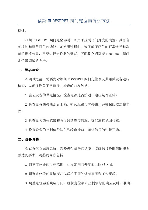
福斯FLOWSERVE阀门定位器调试方法概述:福斯FLOWSERVE阀门定位器是一种用于控制阀门开度的装置,具有自动控制和调节阀门的功能。
在使用过程中,为了确保阀门的正常运行和准确的调节效果,需要进行定位器的调试。
下面将介绍福斯FLOWSERVE阀门定位器调试的方法。
一、设备检查在调试之前,需要先对福斯FLOWSERVE阀门定位器及其相关设备进行检查,以确保设备正常运行。
检查的内容包括:1.验证设备的供电情况,检查电源是否接通、电压是否正常。
2.检查设备的接线是否正确,确认线路没有接错,并确保线缆连接牢固。
3.检查设备的传感器和执行器的连接情况,确保连接稳固可靠。
4.检查设备的控制信号输入和输出接口,确认信号的连接正确。
二、设备调整在设备检查完成之后,需要进行设备的调整,以确保设备的性能和参数达到要求。
调整的内容包括:1.调整定位器的行程范围,即设定阀门开度的上限和下限。
2.调整定位器的灵敏度,以适应不同的调节范围和工作要求。
3.调整定位器的响应时间,确保定位器对控制信号的响应及时、准确。
4.调整定位器的失控保护参数,以确保阀门在出现故障或异常情况时能够及时切断控制信号,以保护设备的安全。
三、系统调试在设备调整完成之后,需要对整个系统进行调试,以确保系统的正常运行和阀门的准确调节。
调试的内容包括:1.验证设备的基本功能,包括手动和自动控制模式的切换、阀门的开度控制等。
2.调试阀门的调节效果,包括调节灵敏度、控制精度、阀门的行程范围等。
3.验证系统的稳定性,通过观察和记录系统的运行情况,判断系统是否存在异常或故障。
4.验证系统的自动保护功能,包括失控保护、异常报警等功能的正常运行。
四、参数调整在系统调试完成之后,如果发现阀门的调节效果不理想或不满足要求,需要进行参数的调整。
调整的内容包括:1.调整PID控制器的参数,包括比例系数、积分时间和微分时间等,以改善控制效果。
2.调整定位器的灵敏度和响应时间,以适应不同的工作要求和调节范围。
福斯阀门定位器调试步骤
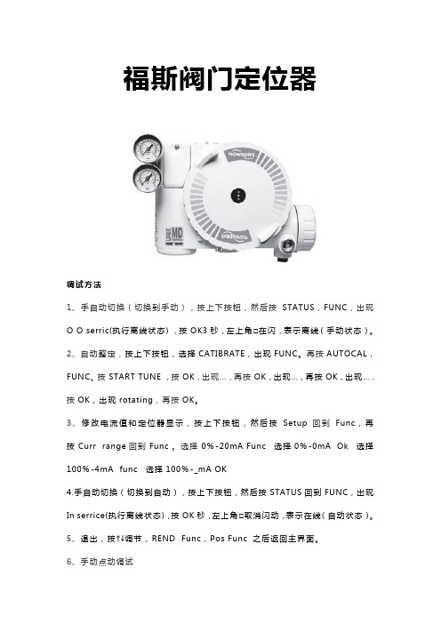
福斯阀门定位器调试方法1、手自动切换(切换到手动),按上下按钮,然后按STATUS,FUNC,出现O O serric(执行离线状态),按OK3秒,左上角□在闪,表示离线(手动状态)。
2、自动整定,按上下按钮,选择CATIBRATE,出现FUNC。
再按AUTOCAL,FUNC。
按START TUNE,按OK,出现…,再按OK,出现…,再按OK,出现…,按OK,出现rotating,再按OK。
3、修改电流值和定位器显示,按上下按钮,然后按Setup回到Func,再按Curr range回到Func。
选择0%-20mA Func 选择0%-0mA Ok 选择100%-4mA func 选择100%-_mA OK4.手自动切换(切换到自动),按上下按钮,然后按STATUS回到FUNC,出现In serrice(执行离线状态),按OK秒,左上角□取消闪动,表示在线(自动状态)。
5、退出,按↑↓调节,REND Func,Pos Func 之后返回主界面。
6、手动点动调试首先将调校DIP开关拨到Jog位置,用户只能手动设置满量程,不能设置全关位,阀门全关位为默认状态。
当DIP 开关拨到Jog位置时,定位器的二极管的状态为黄-红-红-绿。
此时用户再用Jog按钮↑↓手动调节阀门至所期望的100%,阀门到位后,同时按↑和↓按钮,这时阀门自动进行调整,等调整结束后二极管的状态回到黄-红-红-绿,再重新进行100%的设定,设定完成后,同时按↑和↓按钮,阀门进行自动调整。
调整完毕后,二极管的状态以绿色开始。
这表明手动调试完成,定位器正常。
7、就地手动操作QUICK-CAL按钮和↑和↓三个按钮同时按住三妙钟,二极管的状态黄-绿-红-红,此时松开三个按钮,就可以用↑和↓进行阀门开关操作。
按QUICK-CAL按钮即可退出手动操作,恢复自动状态。
福斯FLOWSERVE阀门定位器
福斯FLOWSERVE阀门定位器福斯定位器配置指南福斯(FLOWSERVE)阀门定位器调试方法(锦菲特I3599429OO2)[Q-Q,6696 22933]flowserve阀门、Flowserve 3400IQ定位器、LOGIX500、LOGIX510、LOGIX520、D3系列P-5 气动定位器电动气动数字 - 通用,IS 和 EXHART、Profibus、Foundation 现场总线反馈机组、限位开关比如 PP5XX-HPGU-23K01-PV9DA-3ZPMV P-1700 系列阀门专为腐蚀或高温环境应用设计,其所有外部零件均由不锈钢制造而成。
P-1700 和 1720 型阀门的内部零件采用不锈钢制造,而P-1710 和 P-1730 型阀门的内部零件则采用铝制。
P-1720 和P-1730 型阀门具有超高的空气传送能力。
P-1700 系列阀门专为双向操作应用设计,不过也可通过旋动一个阀座轻松实现单向操作。
不锈钢磁场外壳内的PMV I/P转换器很容易安装在 P-1700 系列阀门上。
P-1500 P-1520P-1700 P-1720P-1710 P-1730Digital具有 PID 控制的2000 数字定位器品牌 Logix说明福斯 Logix 2000 是一款具有板载 PID 控制的数字定位器。
通信方式为 4-20mA 或Modbus。
阀门上安装的 PID 控制器每秒更新阀杆次,从而减少了控制系统延迟。
Logix3200IQ 数字定位器 3200IQ-10-D6-M-04-40-0G-0F3200IQ-10-D6-M-04-40-0G-00品牌 Logix说明福斯 Logix 3200IQ 数字 HART? 定位器使用先进的 piezo 技术提供一流的性能和可靠性。
通过使用本地按钮、HART 手持设备和SoftTools软件可轻松配置 Logix 3200IQ。
LOGIX 3201IQ定位器 P/N:215809.999.000,SN:4107028LOGIX 3202IQ定位器 P/N:221734.999.000,SN:4907010LOGIX 3203IQ定位器 P/N:216428.999.000,SN:610727定位器 P/N:215809.999.000,SN:55070043400IQ Digital Positioner品牌 Logix说明 The Flowserve Logix 3400 Series digital Foundation? Fieldbuspositioner utilizes state-of-the-art piezo technology to provide…500 数字定位器品牌 Logix说明福斯 Logix 500 数字定位器是下一代本质安全型 Logix 500 系列的代表。
福斯中国 - Home - Flowserve Corporation
上海QRC提供多种服务,以维护机械密封件的可靠 性并提高其性能: ● 清洁设备 ● 密封表面研磨机 ● 磨损零件的维修和替换 ● 零件测试和测量设备 ● 密封件测试设备——符合API 682标准 ● 包装设备
惠州QRC
福斯惠州快速反应中心能够向最终用户提供以下 的各项服务: ● 泵的现场安装,开机以及调试 ● 泵的现场维护以及检修 ● 泵的现场对中检测以及调整 ● 泵叶轮的升级以及改造 ● 立式泵动力端的更新 ● 为福斯机械密封提供各项维修服务和升级 ● 生产福斯泵的OEM 备件 ● 为本地生产的备件提供检测报告 ● 技术支持
9
阀门部
凭借业界种类齐全的阀门、执行器、定位器、控制 器和开关产品,以及广泛的研发、工程和全球服 务,福斯为各种应用环境提供完整、周密、精益求 精的流体控制方案。
福斯阀门帮助客户提高设施运转效率,实现生产目 标。我们在化学品、电力、石油化工制品、核应用 领域、炼制、纸浆和纸张、城市用水系统和其他加 工工业有着丰富的实践经验。
电力:
无论在流程、部件还是系统方面,福斯的方案 都能为电站提供帮助。我们一如既往地致力于 改进安全性和效率,提高性能,延长产品寿 命,并减少排放。
核电:
福斯作为核电专家的历史可以追溯到人类利用 核能发电的初始阶段。今天,福斯继承并发扬 其在核电产品与服务方面的优良传统,并且仍 在不断进步的核电技术方面保持领先的地位。
公司可研发、生产、销售泵、环保设备、电机 等机电及其相关部件和配套产品。同时具备同 类产品的批发,佣金代理(拍卖除外)和进出口 业务的能力。公司竭诚为客户提供安装、维修 等工程服务,以及相关售后和咨询服务。
6
福斯解决方案快速反应中心
福斯快速反应中心(QRC)战略性地分布于世界各地, 为客户提供快速的本地支持以维护其设备的正常运 转。我们灵活高效、技术过硬,为您提供个性化的 服务,确保您的工艺设备在操作中保持最佳性能。
Flowserve Automax RG actuator 福斯RG拨叉式气动执行机构
• Torque Outputs: • DA – 248000 Nm (2.2M in-lbs) • SR – 124000 Nm (1.2M in-lbs) • Operating Pressures: • Pneumatic: 2.8-10 bar • Hydraulic: 34-207 bar
Features Feat tur ures
system that significantly reduces transverse loads.
• True M Modular o ular od ar D Des Design esi ign ign • On On-Off, Off M Multi-Position lti Position and nd Th Throttling ottling • Pneumatic, Gas and Hydraulic Models • Spring Return “Fail Safe” and Double Acting
4
RG Series
Heavy-Duty Scotch Yoke Actuator
20% higher break torque
I
nterchangeable Yoke System
• Ductile iron casting • Totally enclosed yoke slot for increased strength and cycle life • Canted yoke results in approx. 20% higher break torque
IP67M Ingress Protection O-Rings or dynamic quad seals are utilized to conform to IP67M specifications, ensuring optimal ingress protection.
Logix
气动仪表
Beta气动定位器
2014 Flowserve Corporation :: Proprietary & Confidential
福斯当前的数字产品:
智能 Logix 420系列
智能 Logix 500+ 系列 HART 智能 Logix 3000MD HART /Ff 智能 Logix 3800 HART /Ff
智能阀门- Fieldbus & Modbus StarPac III
诊断软件 ValveSight® Basic ValveSight® Advanced
STARTALK XP
2014 Flowserve Corporation :: Proprietary & Confidential
Logix 3000MD智能阀门定位器
40
60
80
100
0
20
40
60
80
100
% 控制信号
2014 Flowserve Corporation :: Proprietary & Confidential
% 控制信号
Logix 3000MD智能阀门定位器
• 软限位(用户自定义阀门位置)
100
High Limit
80 % 阀门行程
60
40
20
Low Limit
0
20
40 60 % 控制信号
80
100
2014 Flowserve Corporation :: Proprietary & Confidential
Logix 3000MD智能阀门定位器
• 位置-压力控制
当定位的位置偏差达到设定的范围时,PID控制自动切换到压力控制状态,维 持执行机构压力稳定,减少阀门波动。
- 1、下载文档前请自行甄别文档内容的完整性,平台不提供额外的编辑、内容补充、找答案等附加服务。
- 2、"仅部分预览"的文档,不可在线预览部分如存在完整性等问题,可反馈申请退款(可完整预览的文档不适用该条件!)。
- 3、如文档侵犯您的权益,请联系客服反馈,我们会尽快为您处理(人工客服工作时间:9:00-18:30)。
福斯FLOWSER阀门定位器福斯定位器配置指南福斯(FLOWSERV阀门定位器调试方法(锦菲特I3599429OO2)[Q-Q,6696 22933]flowserve 阀门、Flowserve 3400IQ 定位器、LOGIX500、LOGIX510、LOGIX520 D3系列P-5 气动定位器电动气动数字-通用,IS和EXHART、Profibus 、Foundation 现场总线反馈机组、限位开关比如PP5XX-HPGU-23K01-PV9DA-3ZPMV P-1700 系列阀门专为腐蚀或高温环境应用设计,其所有外部零件均由不锈钢制造而成。
P-1700 和1720 型阀门的内部零件采用不锈钢制造,而P-1710 和P-1730 型阀门的内部零件则采用铝制。
P-1720 和P-1730 型阀门具有超高的空气传送能力。
P-1700 系列阀门专为双向操作应用设计,不过也可通过旋动一个阀座轻松实现单向操作。
不锈钢磁场外壳内的PMV I/P转换器很容易安装在P-1700 系列阀门上。
P-1500 P-1520P-1700 P-1720P-1710 P-1730Digital 具有PID 控制的2000 数字定位器品牌Logix说明福斯Logix 2000 是一款具有板载PID 控制的数字定位器。
通信方式为4-20mA 或Modbus。
阀门上安装的PID 控制器每秒更新阀杆位置16 次,从而减少了控制系统延迟。
Logix 3200IQ 数字定位器3200IQ-10-D6-M-04-40-0G-0F 3200IQ-10-D6-M-04-40-0G-00品牌Logix说明福斯Logix 3200IQ 数字HART? 定位器使用先进的piezo 技术提供一流的性能和可靠性。
通过使用本地按钮、HART手持设备和SoftTools 软件可轻松配置Logix 3200IQ 。
LOGIX 3201IQ定位器P/N : 215809.999.000,SN 4107028LOGIX 3202IQ定位器P/N : 221734.999.000,SN 4907010LOGIX 3203IQ定位器P/N : 216428.999.000,SN 610727 定位器P/N:215809.999.000,SN:55070043400IQ Digital Positioner品牌Logix说明The Flowserve Logix 3400 Series digital Foundation? Fieldbuspositioner utilizes state-of-the-art piezo technology to provide …500 数字定位器品牌Logix说明福斯Logix 500 数字定位器是下一代本质安全型Logix 500 系列的代表。
此定位器提供两种型号。
Logix 510 定位器是一款4-20 mA 模拟定位器,它具有数字控制的所有优点:例如快速效验,诊断功能等等500si 数字定位器福斯LOGIX 500Si 是一款精巧的数字定位器,适用于线性和旋转执行器。
它采用模块化的灵活设计,可根据旋转执行器适用的VDI/VDE 3845 标准进行安装,也可根据带集成管的线性执行器适用的VDI/VDE 3847 标准进行安装。
用户可根据需要选择具有可选插入式开关HART 通信的反馈功能以及进行简单无故障调试的自动校准功能。
品牌Automax说明福斯LOGIX 500Si 是一款精巧的数字定位器,适用于线性和旋转执行器。
它采用模块化的灵活设计,可根据旋转执行器适用的VDI/VDE 3845 标准进行安装,也可根据带集成管的线性执行器适用的VDI/VDE 3847 标准进行安装。
…品牌Logix说明编写福斯ValveAnalysis 用户指南是为了帮助用户更有效地使用与Emerson AMS协同工作的成千上万个阀门。
福斯阀分析是与Emerson AMS结合使用的诊断信号工具。
通过阀分析,StarPac 3 品牌ValtekEP5XX,EP5US,F5-MEC420,D3,P2000,APEX52247Logix3200IQ Digital Positio ner FCD LGENTB0058-02 - 09/05 Logix3200IQ-28-D6-E-04-40-0G-0F P/N:215809.999.000Logix3200IQ-28-N6-E-04-40-0G-0F P/N:221734.999.000Logix3200IQ-10-D6-E-04-40-0G-0F P/N:216248.999.000Logix3200IQ-10-N6-E-04-40-0G-0F P/N:215809.999.000LOGIX3200IQ10D6E0440OGOFLogix3210IQ07D6E0440OGOFLogix3210IQ10N6M0440KG00代表型号:福斯定位器510si-14-W1DEE-0000-000福斯油角阀07AW44.4466PMBYJBY福斯油角阀07AW44.4466PMBYJBY福斯福斯定位器510SI-15-Y20SE-0000-000福斯flowerserve 定位器D3-DIGITAL 黑色flowerserve 600950 福斯定位器520MD-15-WZDEE-0000-000福斯福斯D3-DIGITAL (黑色)订货号:600950福斯定位器D3-DIGITAL 黑色flowerserve 600950福斯油角阀10AW44-4466PMBGY 32.6T PN90 DN25福斯球阀10AW44-4466PMBYJBYJ 32.0TPN90, DN25福斯球阀10AW44-4466PMBYJ BYJ 32.0T PN90, DN25福斯开关盒NXCLU2M1-1800-20(SN#025735不含支架)福斯定位器"510si-14-Y2DEE-F000-000福斯I!福斯油角阀10AW44-4466PM福斯油角阀25A459 56MXZXTZBWCN094B福斯油角阀10 AW44-4466PMBYJBYJ福斯油角阀25 A459 56MXZXTZBWC福斯油角阀10 AW44-4466PMBYJBYJ福斯阀10 AW44-4466PMBYJBYJ福斯阀"05A44 4466 RJ PN102.0 DN15福斯阀10AW44-4466PMBYJBYJ 32.0TPN90, DN25福斯阀10AW44-4466PMBYJBYJ 32.0TPN90, DN25福斯定位器LOGIX 520MD-15-Y1DEE-0000-000福斯球阀10AW44-4466PMBYJBYJ 32.0TPN90, DN25福斯阀10AW44-4466PMBYJBYJ福斯阀07AW44-4466PMBYJBYJ PN90 DN20福斯pmv D3 序列号:904788福斯福斯pmv D3 序列号:904788福斯球阀07AW44-4466PMBYJBYJ PN90 DN20福斯球阀07AW44-4466PMBYJBYJ PN90 DN20福斯阀门定位器520MD-15-W1REE-0003-GM2福斯阀门定位器520MD-15-W1REE-0003-GM2福斯阀10AW44-4466PMBYJBYJ 32.0T PN90, DN25福斯阀10AW44-4466PMBYJBYJ 32.0T PN90, DN25福斯阀07AW44-4466PMBYJBYJPN90 DN20福斯阀10AW44-4466PMBYJBYJ福斯阀10AW44-4466PMBYJBYJ福斯10-RDD40-1SD1EO-D 10 S175663/4-3福斯PNXCLU2M3-18-00200福斯阀10AW44-4466PMBYJBYJ福斯阀05AW44-4466PMBYJBYJ福斯阀40A459-556TT7TZBZMBZM福斯阀20AW44-4466PMBWABWA福斯阀10AW44-4466PMBYJBYJ福斯阀05AW44-4466PMBYJBYJ福斯阀40A459-556TT7TZBZMBZM福斯阀20AW44-4466PMBWABWA福斯阀10AW44-4466PMBYJBYJ福斯阀05AW44-4466PMBYJBYJ福斯阀40A459-556TT7TZBZMBZM福斯阀20AW44-4466PMBWABWA福斯福斯定位器"510si-14-Y1DEE-0000-000I!福斯气动执行机构配件气缸S150D FLOWSERVE 福斯福斯定位器3200MD28-D6-04-40-OG-OF 福斯PNXCLU2M3-18-00200福斯阀型号:1PT4446AGSW R3 A105福斯阀10AW44-4466PMBYJBYJ阀 10AW44-4466PMBYJBYJ 定位器 520MD-15-W1REE-0003-GM2 Logix3200IQ-10-D6-E-04-40-0G-0F Logix3200IQ-10-D6-E-04-40-0G 阀门定位器 3210MD-21-D6-E-04-40-0G-0F 阀门定位器 PMV-D3-70阀门定位器 521MD-15-Y1DEE-00F0-GM2 阀门定位器 3200MD-28-D6-E-04-40-OG-OF 电动阀门定位器 521MD-15Y1DEE-00F0-GM2 电气阀门定位器 3210MD-21-D6-E-04-40-0G-0F 气动阀门定位器 PMV-D3-70 阀 520SI-15-WIDEE-0000-DA3/G1/2 福斯 福斯 福斯 福斯 福斯 福斯 福斯福斯 福斯 福斯 福斯 福斯。