LH-100型稳压器说明书
力普LP100说明书PDF

12
FOR REV JOG FRE SP1 SP2 SP3
RST
ST1 ST2 COM OT1 OT2
24V
TC TB TA
第四章 安装规范
正转 反转 点动 保留
端子控制模式下,正转输入指令 端子控制模式下,反转输入指令 点动输入指令,默认正转
多段速 1~3
三个端子组合成 1~7 段速输入指 令
复位
(
率 给 定 电 流 信 号
拟 信 号 地
(
馈 输 入 电 压 信 号
(
馈 输 入 电 流 信 号
率 表 输 出
正 转
反 转
控 制 信 号 地
点 动
保 留
多 段 速
多 段 速
多 段 速
复 位
加 减 速 时 间 选 择
加 减 速 时 间 选 择
行 频 率 水 平 检 测
行 频 率 水 平 检 测
制 辅 助 电 源
设备中断
频率给定
键盘、键盘电位器、端子 VA(0~5V、0~10V)端 子 IA(0~20mA、4~20mA)
反馈输入
端子 VF(0~5V、0~10V)、
运
端子 IF(0~20mA、4~20mA)
行
运行指令信号
正转、反转、点动
输出信号
故障继电器输出 2A/240VAC 辅助控制信号 OT1、OT2(开集电极输出) 频率表输出(0~5V)
LP-100G-7R5(B)
公司缩写 开发序列
注:铭牌在机箱右侧。
系列标示 G:泛用型
内置制动单元 输出容量
2
第二章 标准规范
二、LP-100G 系列额定输出一览表
型号
电压等级(V) 功率(kW)
稳压直流电源产品说明书
一、 方案设计方案原理框图如图1所示。
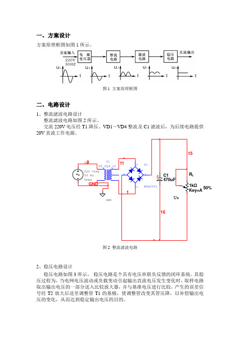
图1 方案原理框图二、电路设计1、整流滤波电路设计整流滤波电路如图2所示。
交流220V 电压经T1降压、VD1~VD4整流及C1滤波后,为后续电路提供20V 直流工作电源。
图2 整流滤波电路2、稳压电路设计稳压电路如图3所示。
稳压电路是个具有电压串联负反馈的闭环系统。
其稳压过程为,当电网电压波动或负载变动引起输出直流电压发生变化时,取样电路取出输出电压的一部分送入比较放大器,并与基准电压进行比较,产生的误差信号经T2放大后送至调整管T1的基极,使调整管改变其管压降,以补偿输出电压的变化,从而达到稳定输出电压的目的。
L50%图3 稳压电路3、输出参数调节及负载电路输出参数调节及负载电路如图4所示。
(1)输出电压Uo 及输出电压调节范围:)U (U R R R R R U BE2Z W 22W 1O +"+++=调节Rw 可以改变输出电压Uo 。
(2)最大负载电流Iomax 。
稳压电源正常工作时能输出的最大电流。
调节Rl 可以改变Io 。
50%Q1图4 输出参数调节及负载电路三、电路测试切断工频电源,连接好被测电路。
1、初测。
稳压器输出端负载开路,断开保护电路,接通220V工频电源,调节电位器Rw,观察Uo的大小和变化情况。
观察结果显示,Uo岁Rw线性变化,说明该稳压电路各反馈环路工作基本正常。
2、测量输出电压可调节范围。
接入负载,并调节Rl,使输出电流Io≈100mA,此时接入的负载阻值为156Ω,满足驱动负载在120Ω~240Ω的范围内,如图5所示。
再调节电位器Rw。
当将电位器Rw调节到最大值时,测量输出电压达到限定范围的最小值,此时Uo为6V左右,如图6所示;当将电位器Rw调节到最小值时,测量输出电压达到限定范围的最大值,此时Uo为15V左右,如图7所示,即满足稳压电源输出直流可调电压6V<Uo<15V这一技术指标的要求。
该过程中如不满足要求,可适当调整R1、R2的值。
LH使用说明书 中英文
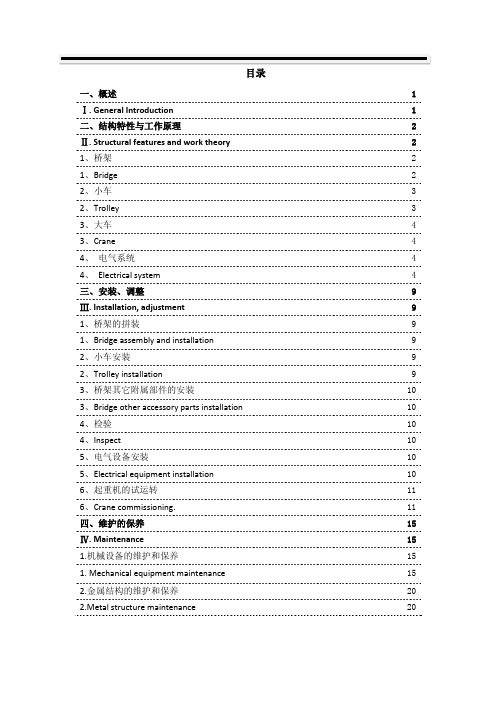
目录一、概述 1 Ⅰ. General Introduction 1 二、结构特性与工作原理 2 Ⅱ. Structural features and work theory 2 1、桥架 21、Bridge 22、小车 32、Trolley 33、大车 43、Crane 44、电气系统 44、Electrical system 4三、安装、调整9 Ⅲ. Installation, adjustment 9 1、桥架的拼装91、Bridge assembly and installation 92、小车安装92、Trolley installation 93、桥架其它附属部件的安装103、Bridge other accessory parts installation 104、检验104、Inspect 105、电气设备安装105、Electrical equipment installation 106、起重机的试运转116、Crane commissioning. 11四、维护的保养15 Ⅳ. Maintenance 15 1.机械设备的维护和保养151. Mechanical equipment maintenance 152.金属结构的维护和保养20 2.Metal structure maintenance 20Ⅰ. General IntroductionLH型电动葫芦桥式起重机(简称起重机)系列是以固定式的钢丝绳电动葫芦作为起重机(主钩和副钩)。
安装在双轨小车上,与双梁桥架配套使用的起重机。
LH type E.O.T. Crane with electric hoist (shortly termed as E.O.T.)Series use fixed wire rope electric hoist as lifting mechanism (Main hook and Auxiliary hook). Fixed on bi-rail trolley, fitted with double girder bridge .本产品适用于机械制造车间、仓库、料场、水电站检修、装配待场所,进行一般吊重装卸作业,本产品的工作环境温度为-25℃~+45℃,不适用于爆炸危险、火灾危险介质中和相对温度大于85%,充满腐蚀性气体的场所,也不使用于吊运熔化金属和有毒、易燃、易爆的物品。
恒流恒压控制模块使用说明书
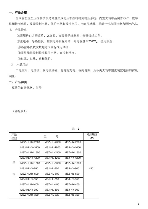
一、产品介绍晶闸管恒流恒压控制模块是高度集成的反馈控制稳流稳压系统,内置大功率晶闸管芯片、数字移相控制电路、反馈控制电路、保护电路和线性电压、电流传感器,是新一代高科技电力调控产品。
⒈产品特点①采用进口方形芯片、DCB板、高级热绝缘材料,特殊焊结工艺。
②主电路、导热基板、控制电路相互隔离,介电强度≥2500V AC,使用安全。
③热循环负载次数超过国家标准近10倍。
④采用线性控制稳流稳压电路,高控制精度。
⑤过流、过热、缺相保护。
⒉产品用途广泛应用于电动机、发电机励磁,蓄电池充电,各类电源,及各类大功率整流装置电源的前级调压。
二、产品种类模块的订货规格、型号:(详见表1)表 11、电流规格为模块正常工作输出最大直流电流平均值或交流电流有效值;电压为模块输入端子间最大输入电压有效值。
2、特殊规格,可按用户要求协议定做。
3、上述表内的型号为常规产品。
当模块需要保护功能时,由用户订货时在模块型号后面加注保护代号。
附:型号义释M xx- xx- xx- x1 2 3 4 5模块订货型号规格共五项,定义如下:第1项:字母M,表示模块。
第2项:模块的类型,定义如下:SZ:三相整流SJ:三相交流DZ:单相整流DJ:单相交流第3项: 模块的功能,定义如下:HL:只有恒流功能HY:只有恒压功能HLHY:具备恒流恒压功能第4项:(2-4)位阿拉伯数字,标记模块的标称电流数。
第5项:模块的保护类别R:过热保护L:过流保护LR:过流过热保护注:对于三相模块,具备过热过流保护时,同时具有缺相保护。
型号示例:MSZ-HLHY-200LR即三相整流200A恒流恒压功能模块,具备过流过热缺相保护功能MSJ-HY-350R即三相交流350A恒压模块,具备过热保护功能注:本册为说明方便,在以下图表中将第3项和第5项省略,以表示各种类型模块。
如:MSZ-350表示350A的恒流、恒压、恒流恒压、有或无保护的各类整流模块。
三模块的使用方法:⒈控制插座引脚功能说明⑪引脚定义1脚:+12V,外接+12V电源正极,工作电流<0.5A。
低压差稳压器快速参考指南说明书

Low Dropout RegulatorsQuick Reference GuideLow dropout regulators (LDOs) are a simple, effective way to regulate an output voltage powered from a higher voltage input. The most critical LDO parameters are input voltage range, output voltage, output current, dropout voltage, packaging size, power dissipation capability, and noise. On this quick reference guide you will find TI’s most popular LDOs and linear voltage regulators for any kind of application.To see the complete LDO portfolio:/ldo L D O12345678 9 1020304050 60 70 80 90 1004+31.510.82V IN (V)I O U T (A )The platform bar is a trademark of T exas Instruments. All other trademarks are the property of their respective owners.© 2016 Texas Instruments IncorporatedSLYT228LMost Critical LDO ParametersTo see the complete LDO portfolio: /ldo• High PSRR (40dB+ @ 100kHz): TPS7A47, LP38798, TPS7A35, LP5907• Low noise (<20μV RMS ): TPS7A47, LP38798, TPS7A35, LP5907• Low I Q (<15μA): TPS780/2 (0.5µA), TPS706 (1µA), TPS709 (1.3µA)• Low dropout voltage: TPS731 (30mV @ 150mA), TPS7A83 (85mV @ 2A), TPS7A85 (150mV @ 4A)• Small packaging: TLV713 (1x1mm), LP5907 (0.65x0.65mm), TLV705 (0.8x0.8mm)• Wide input: TPS7A16 (60V V IN ), TPS7A40 (100V V IN ), TPS709 (30V V IN )• Features: Power good, cap-free operation, reverse current protection, reverse voltage protection, adjustable soft-start and output discharge123 4 5 6 7 8 9 10 20 30 40 50 60 70 80 90 100V IN (V)0.20.150.10.05I O U T (A)0.3 – 0.5IMPORTANT NOTICETexas Instruments Incorporated and its subsidiaries(TI)reserve the right to make corrections,enhancements,improvements and other changes to its semiconductor products and services per JESD46,latest issue,and to discontinue any product or service per JESD48,latest issue.Buyers should obtain the latest relevant information before placing orders and should verify that such information is current and complete.All semiconductor products(also referred to herein as“components”)are sold subject to TI’s terms and conditions of sale supplied at the time of order acknowledgment.TI warrants performance of its components to the specifications applicable at the time of sale,in accordance with the warranty in TI’s terms and conditions of sale of semiconductor products.Testing and other quality control techniques are used to the extent TI deems necessary to support this warranty.Except where mandated by applicable law,testing of all parameters of each component is not necessarily performed.TI assumes no liability for applications assistance or the design of Buyers’products.Buyers are responsible for their products and applications using TI components.To minimize the risks associated with Buyers’products and applications,Buyers should provide adequate design and operating safeguards.TI does not warrant or represent that any license,either express or implied,is granted under any patent right,copyright,mask work right,or other intellectual property right relating to any combination,machine,or process in which TI components or services are rmation published by TI regarding third-party products or services does not constitute a license to use such products or services or a warranty or endorsement e of such information may require a license from a third party under the patents or other intellectual property of the third party,or a license from TI under the patents or other intellectual property of TI.Reproduction of significant portions of TI information in TI data books or data sheets is permissible only if reproduction is without alteration and is accompanied by all associated warranties,conditions,limitations,and notices.TI is not responsible or liable for such altered rmation of third parties may be subject to additional restrictions.Resale of TI components or services with statements different from or beyond the parameters stated by TI for that component or service voids all express and any implied warranties for the associated TI component or service and is an unfair and deceptive business practice. TI is not responsible or liable for any such statements.Buyer acknowledges and agrees that it is solely responsible for compliance with all legal,regulatory and safety-related requirements concerning its products,and any use of TI components in its applications,notwithstanding any applications-related information or support that may be provided by TI.Buyer represents and agrees that it has all the necessary expertise to create and implement safeguards which anticipate dangerous consequences of failures,monitor failures and their consequences,lessen the likelihood of failures that might cause harm and take appropriate remedial actions.Buyer will fully indemnify TI and its representatives against any damages arising out of the use of any TI components in safety-critical applications.In some cases,TI components may be promoted specifically to facilitate safety-related applications.With such components,TI’s goal is to help enable customers to design and create their own end-product solutions that meet applicable functional safety standards and requirements.Nonetheless,such components are subject to these terms.No TI components are authorized for use in FDA Class III(or similar life-critical medical equipment)unless authorized officers of the parties have executed a special agreement specifically governing such use.Only those TI components which TI has specifically designated as military grade or“enhanced plastic”are designed and intended for use in military/aerospace applications or environments.Buyer acknowledges and agrees that any military or aerospace use of TI components which have not been so designated is solely at the Buyer's risk,and that Buyer is solely responsible for compliance with all legal and regulatory requirements in connection with such use.TI has specifically designated certain components as meeting ISO/TS16949requirements,mainly for automotive use.In any case of use of non-designated products,TI will not be responsible for any failure to meet ISO/TS16949.Products ApplicationsAudio /audio Automotive and Transportation /automotiveAmplifiers Communications and Telecom /communicationsData Converters Computers and Peripherals /computersDLP®Products Consumer Electronics /consumer-appsDSP Energy and Lighting /energyClocks and Timers /clocks Industrial /industrialInterface Medical /medicalLogic Security /securityPower Mgmt Space,Avionics and Defense /space-avionics-defense Microcontrollers Video and Imaging /videoRFID OMAP Applications Processors /omap TI E2E Community Wireless Connectivity /wirelessconnectivityMailing Address:Texas Instruments,Post Office Box655303,Dallas,Texas75265Copyright©2016,Texas Instruments Incorporated。
sitranslh100说明书

设计
重量
0.2 kg (0.44 lb)
电气连接
2 x 3 通路(28 到 18 AWG(美国线规))
电缆入口
2 x Pg 9
外壳材料
聚碳酸酯
用于通大气压的通气管
额定条件
符合 IEC 60529 的防护等级
IP65
0.45 %/10 K 满量程
> 6 mH2O ( > 18 ftH2O 或 > 0.6 bar)
0.3 %/10 K 满量程
长(9 ftH2O or 0.3 bar)
0.4% 满刻度值/年
4 ... 6 mH2O (12 ... 18 ftH2O 或 0.4…0.6 bar)
很小的测量误差(0.3 %)
防护等级 IP68
三、产品应用
SITRANS LH100 压力变送器主要用于以下行业:
造船业
水处理/供水
用于在非压力容器/开式容器和水井中使用
四、产品功能
SITRANS LH100 压力变送器、工作模式和连接图
正比于流体液位的静压力作用于传感器 (1) 一侧的膜片 (5) 上。这个压力以大气压作参照。应用连接电缆中的通气管 (3) 完成压力补偿。排泄管配装有一个滤湿器,以防排泄管内形成冷凝。
OC НАНИО «ЦСВЭ»
美国安全检测实验室 (UL)
2014-11-17 - E344532
设备需符合压力设备指令 (PED 2014/68/EU) 的要求
防爆
本安“i”
IECEx SEV 14.0003
SEV 14 ATEX 0109
标记
II 1 G Ex ia IIC T4 Ga
接线盒
变压器、电压调节器、电力调节器、灯光控制、运动控制等产品说明书
PS100GR RP250GR RS100GRVARIABLE TRANSFORMERS • VOLTAGE REGULATORS • POWER CONDITIONERS • LIGHTING CONTROLS • MOTION CONTROLS5-WA Y ®Binding Posts and SUPERCON ®Electrical Connectors2Standard and Miniature Single Assembly5-WA Y® Binding Posts5-WA Y® Binding Posts have positive-stop captivethumbnuts that allow space to make connectionsyet reduce the likelihood of accidentally contactingcurrent carrying parts. They are available in red,white, blue, yellow, black and green. BP31 flutednut types have insulating parts of Lexan® polycar-bonate resin which has a higher DC insulation re-sistance at all operating temperatures and signifi-cantly lower capacitance which provides greaterresistance to high frequency leakage effects. Allothers have nylon plastic per MIL-P20693A, T ypeIV. Current carrying parts are gold, nickel or tinplated brass for improved conductivity and corro-sion resistance. Metal parts are recessed for userand instrument protection and none touch themounting panel. All are available in single packs or100-quantity bulk packs. They are UnderwritersLaboratories recognized components.Standard Hex Nut and Fluted Nut Types -Ratedfor 30 A, 1000 V working.Miniature Fluted Nut Types -Rated for 15A,1000 V working.** T ype numbers given are for binding posts with gold plated brass parts. For nickel plated brass parts addsuffix N, for tin plated brass parts add suffix T; for example, BP30GNN (nickel) or BP30GNT (tin). Ordersingle pack quantities by adding suffix “-1 PKG”, for example BP21R-1 PKG; order bulk pack quantitiesby adding suffix “-B PKG”, for example BP21R-B PKG.TYPES BP30 and BP31 DIMENSIONSTYPE BP21 DIMENSIONS*Lexan is a General Electric T rademarkBP30GNBP31RBP21B3Larger Stud Single Assembly5-WA Y ®Binding PostsLarger stud single assembly types have the same features as types described on page 2 but have a larger #10-32 stud for behind the panel connections.Grounding type is made of polished nickel plated brass.Larger Stud Hex Nut and Fluted Nut Types -Rated for 30A, 1000 V working.All Metal Grounding Type BP30GP10 - For mak-ing rapid connections to ground.** T ype numbers given are for larger stud binding posts with gold plated brass parts, except BP30GP10 which is nickel plated. For nickel plated brass parts add suffix N, for tin plated brass parts add suffix T; for example, PB30-10GNN (nickel) or BP30-10GNT (tin). Order single pack quantities by adding suffix “-1 PKG”, for example BP30-10B-1PKG; order bulk pack quantities by adding suffix” -B PKG”, for ex-ample BP30-10B-B PKG.BP31-10RBP30-10GNBP30GP10TYPES BP30-10 and BP31-10 DIMENSIONSTYPE BP30GP10 DIMENSIONS4Standard, Miniature and Larger Stud Double Assembly5-WA Y® Binding PostsDouble Assembly 5-WAY® Binding Posts aredesigned for faster, more accurate mounting on3/4-inch (19mm) centers. Conventional miniature,standard and larger stud types have panel insulat-ing parts in black only. Thumbnuts are available incolor combinations of red and black, black and blackand red and red. Plastic insulating parts have thesame characteristics as single types. Metal partsare available in gold, nickel or tin plated brass parts.Double assembly types are available in single packsor in 10-quantity bulk packs. All are UnderwritersLaboratories recognized components.Standard Hex Nut and Fluted Nut Types -Ratedfor 30 A, 1000 V working.Miniature Fluted Nut Types -Rated for 15A,1000 V working.* Order single pack quantities by adding suffix “-1 PKG”, for example BP30-2BB-1 PKG;order bulk pack quantities by adding suffix “-B PKG”, for example BP30-2BB-B PKG.5TYPE BP21-2BR DIMENSIONSTYPE BP30-2BR DIMENSIONSBP30-2BRStandard, Miniature and Larger Stud Double Assembly5-WA Y ®Binding PostsBP30-2BR10TYPE BP30-2BR10 DIMENSIONSBP21-2BR6Custom Color Ring5-WA Y ® Binding PostsAll cataloged Custom Color Ring Series types have neutral gray plastic insulating parts. Single assem-bly types have thumbnut-imbedded rings in red,white, blue, yellow, black or green plastic while double assembly types have thumbnut color rings in black-red only. All are available with current car-rying parts in gold, nickel or tin plated brass. BP31Series fluted nut types have insulating parts molded of Lexan polycarbonate resin which has a higher DC insulation resistance at all operating tempera-tures and significantly lower capacitance which pro-vides greater resistance to high frequency leakage effects. All others have nylon plastic per MIL-P-20693A, T ype IV . All types with “-10” in the suffix have larger 10-32 studs for making behind the panel connections. Contingent upon minimum quantityrequirements, insulating part color can be custom-ized. Inquiries are invited. Single assembly types are available in single packs or 100-quantity bulk packs; double assembly types are available in single packs or 10-quantity bulk packs. They are Under-writers Laboratories recognized components.Single Assembly Standard Hex Nut and Fluted Nut Types - Rated for 30 A, 1000 V working.Single Assembly Miniature Fluted Nut Types -Rated for 15A, 1000 V working.Double Assembly Standard Hex Nut and Fluted Nut Types - Rated for 30 A, 1000 V working.Double Assembly Miniature Fluted Nut Types -Rated for 15A, 1000 V working.SINGLE ASSEMBL Y TYPESDOUBLE ASSEMBL Y TYPES* Enter desired ring color code: R (red), B (black), BL (blue), GN (green),WT (white), Y (yellow).** Enter desired ring color code: R (red), B (black), BL (blue), DG (green), WT (white), Y (yellow).† T ype numbers given are for binding posts with gold plated brass parts. For nickel plated brass parts add suffix N, for tin plated brass parts add suffix T; for example, BP30GY1RN (nickel) or BP30GY1RT (tin). Order single pack quantities by adding suffix “-1 PKG ”, for ex-ample BP21GY1R-1 PKG; order bulk pack quantities by adding suffix “-B PKG ”, for example BP21GY1R-B PKG.SUPERCON®Electrical ConnectorsSUPERCON® Electrical Connectors incorporate many advanced engineering features designed to provide safe, rapid and positive panelboard con-nections. Single conductor socket and pin type plugs and receptacles are offered in 25, 50, 100 and 250 Amp capacities.The 25, 50 and 100 Amp types are rated 125-250 VAC or DC current interrupting, 600 V unenergized connect or disconnect use only; 250 Amp types are rated 600 V unenergized connect or disconnect use only. The 25, 50 and 100 Amp types are CSA certi-fied under file No. LR-17812.PLUGS -Plugs have a unique functionally designed grip for handling ease and convenience. The vari-ety of red, white, blue, yellow, black or green colors permits wider latitude in patchboard distribution lay-outs. Wiring connection to the same plug can be either soldered or solderless. Cable fastening screws are provided which permit a range of cable sizes to be accommodated by the plug. All plug grips are of a simple, two-piece threaded construction for quick assembly.RECEPT ACLES - Receptacles have color-matched nylon caps and bodies. All plastic parts of a recep-tacle are molded through in the same color to per-mit more rapid and accurate circuit identification on both the front and back of the panel when installed. Wiring connections are made to a threaded stud by wire wraparound, by lug or bus bar connection.78SUPERCON®Electrical ConnectorsRS25GRPP25GRRP25GWTPS25GWTRS100GBPP100GBRP100GGNPS100GGN925 AMPERE TYPES OUTLINES50 AMPERE TYPES OUTLINES100 AMPERETYPES OUTLINES10RS250GYPP250GYRP250GRPS250GRSUPERCON®Electrical Connectors250 AMPERE TYPES OUTLINES11Other Voltage Control ProductsSTABILINE ® Power Protection ProductsST ABILINE ® Power Protec-tion Products include cabinet and rack mount WHR Series Voltage Regulators with rat-ings to 1680 kVA, SW and SPW Series Uninterruptible Power Supplies that regulate voltage and provide battery backup in event of power fail-ure, PPC Series Power Con-ditioners to protect from power sags, spikes andsurges.POWERSTAT ® Variable TransformersThe most recognized brand in the technology, the POWERSTAT ®Variable T ransformer line includes 31 series in either single or three phase 120, 240 or 480 V types in ratings from 0.13 to 365 kVA. They are available in manual and motor driven, portable with and without meters, open and enclosed mod-els. Epoxy-coated POWERKOTE ®Coils give 20% average higher current ratings, greater overload capacity .LUXTROL ® Light ControlsLUXTROL ® Light Controls are available for the control of incandescent lighting. T ypes includewallbox style manual WBD Series in ratings to 1800 watts and manual and motor driven 2000and 5000 watt D series.Distribution Coast-to-Coast and InternationalSuperior Electric products are available worldwide through an extensive authorized distributor network. These distributors offer literature, technical assistance and a widerange of models off the shelf for fastest possible delivery and service.In addition, Superior Electric sales representatives are available to provide promptattention to customer needs. Call or fax for ordering and application information or forthe name and address of the nearest authorized distributor.383 Middle StreetBristol, CT 06010 USAT el: 860-585-4500Fax: 860-582-3784Web: Toll Free in USA and CanadaCustomer Service: 1-800-787-3532 - Ext. 4750Product Application: 1-800-787-3532 - Ext. 4755Product Literature Requests: 1-800-787-3532 - Ext. 4750Fax: 1-800-821-1369383 Middle Street • Bristol, CT 06010 USAT el: 860.585.4500 • Fax: 860.584.1483Printed in USAPS100GR RP250GR RS100GR。
LW100中文使用说明书
爱安达LW 100系列使用手册LW 100 BLW 100 ELW 100 E1总论本手册包含安全使用LW充气机所必需的操作及保养程序。
所以请事先认真阅读并严格执行,任何违反说明所造成的后果不在本公司的保修范围内。
注意以下几点:●试用期内只充气瓶●请勿超过容器允许压力等级●对过滤系统做好保养●避免污染空气进入进气口●不得超出最高工作温度安全手则●仔细阅读操作手册●只允许专业人员操作本充气机●操作时,不得放置任何物体于机上●运转时,确保无任何人或物体触及运作的部件●确保进气清洁,无有毒气体●必须在拔掉充气机电线插头及泄压后,才可进行维护工作●定期检查是否漏气或漏油●不得焊接损坏的高压气管●充气管必须处于良好的工作状态,必须特别注意接口处●任何维护工作之前,必须拔掉电线插头●维护时,不得触及高温部件,待冷却后进行工作呼吸空气压缩机(LW100B;LW100E;LW100E1)应用便携式高压呼吸空气压缩机适用于移动或其他轻量充气应用.发动机LW100B:强力万达牌V4冲程发动机(4.5千瓦),集成式燃料箱,手拉式启动;低油水平时停机.LW100E:2.2千瓦电动马达/400伏3相电压 /50赫兹开关按钮,可连接电缆和16安CEE插口LW100E12.2千瓦 E 发动机/230伏电压/50赫兹或者60赫兹开关按钮,可连接电缆和CE插口配置∙不锈钢提携结构∙3级压缩机机头∙全部活塞带金属活塞环∙水/油分离器∙每级压缩有安全阀∙压力维持止回阀∙带不锈钢头的充气软管∙带压力表充气阀∙充气连接(DIN200巴带YOKE接口或DIN3OO巴)∙便携手柄∙呼吸空气净化纯度符合 EN12021/DIN 3188/ISP2533规程∙过滤器容量:在20摄氏度时大约为108立方米选项∙要加带充气阀和气瓶连接的进气软管∙替换的一套压力开关,以及限压300巴的安全阀,选择阀和第二只充气管/阀/连接装置∙终压时自动停机装置∙特选电压/频率充气首次充气前,请检查在额定工作压力条件下的最终安全阀和其他进气连接装置,以确保工作压力及(在充气时)能让压缩机自动停机(如果可能的话)的正确操作:这是通过关闭充气阀和压缩机来完成的,让压缩机形成压力,压力表将在压力维持表打开(大约启动后1分钟左右),才显示压力的增加.压力将增加到安全阀泄放或者自动切断压缩机.如果压缩机超过额定工作压力,而安全阀门不能自动泄放,请立即手动关闭压缩机并询问技术工程师。
Excitrol-100微机励磁调节器的技术参数与原理
Excitrol-100微机励磁调节器的技术参数与原理摘要本文介绍了Excitrol-100微机励磁调节器的主要技术特点及其基本原理,其采样后的数据处理方式为快速傅里叶变换,Excitrol-100微机励磁调节器性能优越其应用十分广泛。
关键词Excitrol-100微机励磁调节器;技术参数;原理;数据处理方式;WLK-100系列微机控制同步电动机励磁装置是北京前锋科技有限公司研发的最新一代同步电动机励磁系统,其核心控制单元为excitrol-100型微机控制同步电动机励磁调节器,该系列装置包含WKLF-101装置,具有除双套自动跟踪和故障自动切换外的全部技术性能。
Excitrol-100励磁调节器为架构独立的控制单元,其功能涵盖了励磁系统所有测量、控制、调节与保护,如触发脉冲形成与功率放大、模拟量变送、接点量开入开出、启动回路控制、参数整定与励磁调节、软硬件故障监测、双机通讯、后台通讯、与PC机或液晶操作面板通讯等等。
采用双调节器配置是双机只通过CAN通讯电缆连接,无任何公用部分,真正做到百分之百软硬件冗余。
采用Excitrol-100励磁调节器只需另外配置励磁主回路,用于励磁电流电压测量的霍尔传感器及简单的操作指示元件即可构成整套励磁系统,各部分功能明确,结构简洁。
Excitrol-100微机励磁调节器的核心处理单元为32位DSP处理器,其主要技术指标包括:150MHz的主屏速度、32位数据总线宽度、128K字片内FLASH 存储器、18K字片内RAM、16路12位A/D采集器,多种模式的串行通讯控制其及功能强大的脉冲宽调控制器等。
DSP优异的数字信号处理能力为调节器的技术性能实现提供的坚实的基础。
Excitrol-100微机励磁调节器是WKLF-102微机控制同步电动机励磁装置的核心控制、励磁调节及保护单元。
本装置采用两台软硬件功能完全相同的Excitrol-100微机励磁调节器分A、B套运行,A、B套均可以以主机运行,当A (B)套调节器为主机运行时,B(A)套调节器自动转入备机运行时,备机不接受任何励磁操作控制(通讯及调节器配置,录波器操作等除外)备机自动跟踪主机的运行参数及状态且其触发脉冲及控制输出完全被封锁(故障报警输出除外),主、备机分别不断进行各自的软硬件自检及运行参数测量,与备机相比,主机还要不断进行励磁的控制与调节,并判断励磁调节是否正常。
稳压器通用说明书
稳压器通用说明书稳压器通用说明书WG-3000 ·WG-5000 ·WG-8000交流自动稳压器说明书使用前请认真读本说明书。
感谢您选用了‘JUTA’牌交流自动稳压器,愿我们的产品及服务能为您带来更多方便和实惠功能:在市电输入变化时自动调整稳压输出,确保家用电器在恶劣的电网条件下也能正常运行;同时具备了全方位保护及实用的稳压、市电直通功能,使用方便,更安全更可靠,大大延长了家用电器的使用寿命。
⊙ 稳压精确:在电网电压变化不稳时,能输出稳定的安全电压,使用电器不受影响。
⊙ 输入欠压、过压保护:由电网及其他因素引起的电压输入过高或过低时,为保证用电器和人身财产安全,稳压器会自动切断输出,待电网电压恢复稳定后可自动(延时)开启。
⊙ 缺相保护:在三相供电情况下,由于一相断掉或者零线断掉,会导致单相供电电压异常升高,甚至高过380V,危及到用电器及人身财产安全,此时稳压器会自动关闭输出进入保护状态。
⊙ 误断电保护:在遇到电网老化、输电线过细距离过长时,有感性负载(如冰箱、空调等带有压缩机的)或大型用电器启动,瞬间会导致电网电压降低,此时稳压器能保证负载的正常供电而不至于误断电。
⊙ 市电稳压切换:机身侧面设有稳压接入和市电直通转换开关,使用时若觉得电网电压很稳定,不想用稳压功能时,把此开关拨至“OFF”市电状态即可。
通常情况下都要将此开关拨至“ON”稳压状态,此时自动稳压功能才能启动。
⊙ 延时供电功能:为避免短时间停电又来电情况的’发生,设有了2-3分钟自动延时供电功能(如电冰箱或空调器在停止工作后,再次启动需3分钟延时);若不需要此延时,可按下“延时开关”按钮启动短延时,本机可在5秒内开启供电。
安装连接:将启动开关拨至“OFF”关状态,拉下电网闸刀开关或空气开关断开市电,取下稳压器端子板两颗固定螺丝拔出端子板,按对应端位指示正确连接。
1.把家庭供电总线(墙壁插座及所有用电器用线)插入到对应输出的“火线”、“零线”端口内,拧紧固定螺丝。
- 1、下载文档前请自行甄别文档内容的完整性,平台不提供额外的编辑、内容补充、找答案等附加服务。
- 2、"仅部分预览"的文档,不可在线预览部分如存在完整性等问题,可反馈申请退款(可完整预览的文档不适用该条件!)。
- 3、如文档侵犯您的权益,请联系客服反馈,我们会尽快为您处理(人工客服工作时间:9:00-18:30)。
一、产品概述市场中的节电装置大都不具备稳压的功能,仅仅降低装置的供电电压,从而达到节电的目的。
其弊端为:当电网电压稍有波动时,装置的输出电压升高,不再节电;或者输出电压降得更低,对负载的影响较大。
由此可见,稳压功能是节电装置必备的一项功能,也是能够实现节电的必要条件。
LH-100型智能节电装置根据用户电网电压的波动情况、照明负载的性质,为负载提供稳定的供电电压。
用户可根据需求,设置输出电压,对负载的运行时间和供电方式进行编程,最大限度地降低负载的电耗。
二、结构它是由三相补偿变压器、三相调压变压器、传动机构、电刷接触系统、箱体和控制系统等组成。
三相调压变压器圆筒式绕组外表面经磨光加工,去除绝缘,呈光滑的导体面,以便于电刷良好接触;传动机构由电动机和蜗轮、蜗杆、链轮、链条组成;电刷系统结构合理可靠,以保证电刷压力;箱体采用封闭柜式,体积小,散热好,检测仪表位置醒目,提示准确。
三、工作原理LH-100系列节电装置由三相补偿变压器TB、三相调压变压器TUV电压检测单元、电动机控制与传动机构,接触操作电路等组成,其电气原理图一所示。
图一自动补偿电力稳压器电气原理图调压变压器TUV的一次绕组接成Y形,连接在稳压器的输出端,二次绕组连接补偿变压器TB的一次绕组,而补偿变压器工作原理,如图二所示。
若不计补偿变压器阻抗压降,则从图二可见:Uao=Uai+Uac式中:Uai—稳压器A相输入电压;Uao—稳压器A相输出电压;Uac—稳压器A相补偿电压;图二单相补偿电力原理图其原理是:当A相输入电压Uai增加ΔUai时,补偿电压Uac也相应改变ΔUac且ΔUac=-ΔUai时,使A相输出电压Uao保持不变,同理B相、C相也是如此。
其稳压调压过程是:根据输出电压的变化,由电压检测单元采样,检测并输出信号控制电动机SM转动,经减速机构并有链条带动调压变压器TUV上的电刷组滑动(或滚动)来调节调压器的第二次电压,以改变补偿电压的极性和大小,降低或升高输出电压,进而达到节电的目的。
四、基本部件与电路1、补偿变压器当一次线圈上所加电压的大小和极性发生变化时,能使串联在负载回路上的二次线圈产生幅值和极性可变的补偿电压变压器。
2、调压变压器调压变压器TUV是一台能自动调节二次电压的三相自耦变压器。
它具有三对能自动对称滑动的电刷。
电动机经链条带动电刷沿自耦变压器圆筒式绕组裸露部分(滑道上)滑动,平稳地调节二次电压,以达到改变补偿电压,维持输出电压稳定的目的。
3、电动机控制电路(见图四)伺服电机控制方式有“手动”、“自动”两种,由切换开关QT1选择。
在“手动”位置时:要提高输出电压按SB3“升压”按钮,要降低输出电压按SB4“降压”按钮,直到输出电压符合供电要求,此时,本机不具有稳压功能;选在“自动”时:升压和降压检测单元自动控制,实现“自动”稳压功能。
4、三相主电路开关装置及操作电路1)稳压主电路设置了一只自动开关Qa、一只接触器和一只刀开关。
(详见图4)是为使电压自动补偿系统能方便地投入和退出而设置的。
投入稳压运行时,只要把刀开关手柄置“稳压”按钮,按“稳压”按钮,交流接触器合上即可;需要电网直接直通时,只要把刀开关手柄置“市电”位置即可。
2)在接触器合闸电路中串联了过压和欠压保护继电器Kc3和相序、缺相保护继电器KC4的常开接触点,在稳压运行中,只要输出端电压、欠压或缺相、错相时即能自动跳闸保护,并报警,需按“停止”按钮,清除保护状态后才可启动。
3)500KV A以上节电装置省略交流接触器和QA开关,采用DW系列万能式自动空气开关断路器实现断路,当过压、欠压、缺相、错相时补偿系统自动退出运行。
5、三相稳压器电压检测和调节单元采样控制变压器TC从稳压器输出端取出采样电压和控制电压,控制电压经变压、整流滤波及稳压后由RP1、RP3分压得到上限基准电压。
采样电压经变压、整流、滤波得到随输出电压变化的信号电压,输出到比较器进行比较,当信号电压处于上限和下限基准电压之间时控制继电器KC1、KC2触点均处于断开位置。
当信号电压超过上限和下限基准电压即(精度)时,KC1(KC2)和接触电器KA1(KA2)动作。
电动机转动调节补偿电压、使稳压器输出电压稳定。
总之,当输出电压变化超过额定精度允许范围时,电压检测便发出调节输出电压指令,直到输出电压恢复到额定精度允许的范围。
节电装置的稳定精度由电位器RP3在±1%至5%之间调整。
额定输出电压的中心位置由调节电位器RP1来调整。
6、三相保护电路1)自动开关QA保护主电路过载及短路。
QLS1和QLS2限位开关组成越限保护电路:当电刷滑动触及上下限位开关时,其电压调节继电器的线圈失电,使继电器释放,伺服电机停转,达到越限保护作用。
2)过压和欠压保护在正常运行状态下控制继电器KC3常闭触点,处于闭合状态,当信号电压高于过压保护额定电压或低于欠压额定保护电压时(过压电压设定为420V左右,欠压电压设定为320V),保护继电器常闭点断开,并使接触器KM断开自动补偿系统退出工作状态时,同时发出声光告警。
3)相序和缺相保护电路。
当三相电源进线相序错位或缺相时,相序保护器指示灯不亮,整机处于自动保护状态。
7、本机设有A、B两块控制板,在使用过程中,若发现A板控制有故障,可拨动备用板转换开关至B板,B板即可代替A板投入使用。
8、单相稳压器电压检测和调节单元单相稳压器电压检测和调节单元的工作原理和三相稳压器电压检测和调节单元完全相同。
自动开关QA保护主电路过载及短路,电压自动补偿系统设置了越限保护。
越限保护由QLS1和QLS2限位开关组成,当电刷滑动到两端碰撞限位开关时,其常闭点断开,电动机停转。
过压保护电路在正常运行状态下,控制继电器常闭触点闭合状态,当信号电压高于过压保护额定值时,控制继电器常闭触点断开使接触器KM断开,自动补偿系统退出工作。
自动和分调稳压器电路如图三、图四、图五、图六。
五、型号六、主要技术指标与规格1.技术指标(1)节电率:综合节电率可达10%~45%;(2)软启动预热:灯具刚点亮时,节电装置输出195V~225V软启动预热电压,约十分钟(可调)后,自动转入稳压节电状态;(3)无级调压:可在190V~230V之间任意选择输出电压值,以及电压变化的时间段,节电柜会根据时间将输出电压自动缓慢地转变到设定值;(4)时控功能:每天可设8个时段,每个时段可输出不同的节电电压(任意确定);(5)优化功能:补偿变压器的绕组能抑制负载电流的瞬变,优化输出电压质量;(6)过、欠压保护:当输出电压超出设定值±10%时,装置将自动切换到“旁路”状态,转到市电供电;(7)短路保护:当输出端出现短路时,空气开关自动切断输入电源;(8)集中监控系统(可选):可加装照明集中监控系统,对各个路段的照明进行遥测、遥信、遥控;(9)无功功率补偿(可选):可加装无功功率补偿功能,补偿值根据现场负载情况,由用户自定。
2.性能指标产品选型七、使用条件LH-100系列智能节电装置应在室内使用,正常使用条件为:1、环境温度:-5℃~+45℃;2、海拔高度:不超过1000米;3、相对湿度:≤90%;4、安装场所应无产生影响稳压器绝缘的气体、蒸气、化学沉积、灰尘、污垢及其他爆炸和侵蚀性物质;5、安装场所应无严重震荡或颠簸;6、凡不符合上述规定的特殊使用条件,应由使用单位和我厂协商决定。
八、订货须知1、订货时应说明产品型号、容量、额定输出电压、输入电压变化范围、稳定精度、电源输入位置。
2、有特殊要求,请与本厂技术部联系,你将获得完善的专业咨询。
2)测试点对地(机外壳)用1000V兆欧表测试绝缘电阻值应大于1M Ω,如小于1MΩ应检查原因,或用电热器烘干柜内潮气,直到绝缘电阻达到标准为止。
4、安装接线1)225kV A节电装置以下连接进线:输入电源A、B、C三相导线由柜后下方引进穿进电流互感器,(匝数按铭牌要求)接至柜内空气开关的桩头(标有输入接线A、B、C字样)2)320kV A以上节电装置连接进线:输入电源A、B、C三相导线接至空气开关(或空气断路器)上桩头所对的铜母排上(母排上标的输入电压及A、B、C字样)3)多柜产品柜间连接线:双柜和四柜产品的柜间连接线,可选用不小于1mm²铜软线在柜间端子接线排上按上至下对应连接即可。
4)连接输出线:节电装置上标有“输出电压”的各接线端子接负载,连接线规格由用户根据负载大小而定,一般应与进线线规相同。
5)机壳保护接地:接地线线规应按当地供电部门有关规定执行,接地线应接至机柜内标有“接地线”的桩位上,接地线电阻应小于0.4MΩ。
5、检查接地调试人员的第一步工作也是最重要的一项工作是仔细检查接地,这项工作是保证节电装置可靠运行的关键,必须认真做好。
具体工作内容如下:1)检查主回路接线是否牢固可靠,尤其对QA空气开关、ON刀开关与Km接触器点接线有否松脱现象,如有松脱,必须拧紧。
2)检查面板背面各种电气器件,如电压表、电流表、指示灯按钮、转换开关的接点连线是否牢固可靠。
如有松脱,必须拧紧。
3)检查控制电路板,各点接线是否松动。
如有松脱,必须拧紧。
4)检查控制箱内控制电路板及电机供电的C45电源开关是否合上。
6、通电调试操作1)将面板上“手动”/“自动”选择开关(QT1)放置“手动”档位置。
2)ON刀开关置“稳压”位置。
稳压器处于空载状态,接通电源,合上空气开关QA,这时面板上的三相电源指示灯亮,输入电压表有读数,即完成输入电源通电试验。
3)按“稳定”按钮SB2,大约延迟5-15s后,延迟继电器KC5闭合使输出接触器KM得电闭合,机板上绿色“稳压”灯亮。
然后,根据输出电压表V0的读数,按“升压”按钮SB3或“降压”按钮SB4,输出电压表指针随之升或降,即完成手动调试试验。
注意事项:当按稳压按钮SB2后节电装置不能启动,相序保护器指示灯不亮,表示三相相序错接。
排除方法应先切断电源。
只要将三根进线中的任意两根线位置进行调换即可。
当按稳压按钮SB2后,稳压即有输出电压,但瞬间出现报警并自动跳闸保护,表示接线正确,由于输入电压偏高,输出电压也跟随偏高且高于电压保护值。
此时应将“手动”/“自动”选择开关(QT1)放置“自动”档位置。
再按稳压SB2。
观察输出电压表V0的读数稳压380V后,再进行4)操作,调试“升压”和“降压”两种情况下,节电装置是否稳压(380V)。
若出现异常请速与本厂联系。
4)将“手动”/“自动”开关放置“手动”档位置不变,然后按SB3“升压”按钮,使输入电压达到400V左右,把QT1开关转换到“自动”档位置,稳压器输出随之下降到380V左右,这是升压试验,将“手动”/“自动”开关放置“手动”档位置,然后接着按SB4“降压”按钮使输出电压为360V左右,把QT1开关转换到“自动”一档的位置,输出电压随至上升到380V左右。