8路干接点输入,继电器输出,开关量
环境综合采集单元技术要求

1、环境综合采集单元技术要求
产品功能要求:
1、实现机房环境的模拟量、开关量数据采集。
通过串行数据和网络IP
数据包进行转换及远程管理。
2、系统可以接入8路模拟量(4-20mA)采集,8路开关量。
实现对温湿
度、红外、烟感防盗,机房动力环境进行监测。
3、系统遥控功能:实现对空调,风机、水泵的控制。
4、通信接口具有保护功能。
产品具体参数要求:
备注:通讯接口方式为前面板出线,4个485接口,1个以太网接口。
软件要求
1、实现机房环境的模拟量、开关量数据采集。
通过网络IP数据包进行
转换及远程管理,提供本地维护调试程序(windows系统)。
2、根据现场情况通过修改装置程序模块接入不同的智能设备。
3、4个485接口通信参数速率、校验位、停止位可通过网络设置,4个
485接口具有通过网络数据转发功能(后台机通过TCP/IP协议访问相
应的485接口)。
4、严格按照提供通信协议,进行数据格式向管理机通信。
环境综合采集单元1U单元机壳后视图。
FT-RS-0808A(MODBUS-RTU协议)8路开关量输入8路开关量输入说明书VA8.1.1

将主计算机串口接转换器(RS-232/RS-485),转换器输出 A 端和所有模块的 A 端连接,B 端和所有模块的 B 端连接,并在两终端接入匹配电阻(距 离较近时,也可不用),接入电源。
FT-RS-0808A 模块出厂时,都已经过测试,且模块地址为 01 号,波特率为 9600bps。模块地址从 1-247 随意设定;波特率 9600bps.使用。 模块地址 01
0006H 0007H 0008H 0009H 000AH 000BH 000CH
参数 7 参数 8 参数 9 参数 10 参数 11 参数 12 参数 13
DI1 扩展功能设置 DI2 扩展功能设置 DI3 扩展功能设置 DI4 扩展功能设置 DI5 扩展功能设置 DI6 扩展功能设置 DI7 扩展功能设置
是否主机断线 复位 DO
数据数据范围 0-7,对应波特率 1200-115200
地址范围 1-247 ,公共地址 0 数据范围 0-15 数据范围 0-2 0:DI 不联动 DO 1:DI 联动 DO,DI 有效 DO 有效,DI 无效 DO 无效, 2:DI 联动 DO,DI 有效 DO 输出和上次取反输出。 10:DI 输入处理由独立的设置来决定(参数 6—参数 14)
数据范围:0-65535,单位秒 如果数据为 0,则不检测主机断线,如果数据大于 0,则运行主机 断线复位功能 如数据为 0064H,则为 100 秒,是指模块在 100 秒钟之内,如果没 有接收到主机数据,则将模块输出关断(继电器都断开)
0005H
参数 6
模块返回数据延迟 模块收到主机数据,额外延迟时间设置值域 0-65535mS
数据范围:0-65535,单位秒 如果数据为 0,则不检测主机断线,如果数据大于 0,则运行主机断 线复位功能 如数据为 0064H,则为 100 秒,是指模块在 100 秒钟之内,如果没有 接收到主机数据,则将模块输出关断(继电器都断开)
SD测速和超速保护卡SDP及端子板说明(有路DOC
测速和超速保护卡(SDP)及其端子板使用说明(有6路模拟量输入)编制:⎽⎽⎽⎽⎽⎽⎽⎽⎽⎽⎽⎽⎽⎽⎽⎽⎽⎽⎽⎽校对:⎽⎽⎽⎽⎽⎽⎽⎽⎽⎽⎽⎽⎽⎽⎽⎽⎽⎽⎽⎽审核:⎽⎽⎽⎽⎽⎽⎽⎽⎽⎽⎽⎽⎽⎽⎽⎽⎽⎽⎽⎽审定:⎽⎽⎽⎽⎽⎽⎽⎽⎽⎽⎽⎽⎽⎽⎽⎽⎽⎽⎽⎽批准:⎽⎽⎽⎽⎽⎽⎽⎽⎽⎽⎽⎽⎽⎽⎽⎽⎽⎽⎽⎽新华控制工程有限公司二00四年四月转速测量和超速保护卡及端子板使用说明1. 概述SDP卡是转速量测速和超速保护功能合二为一的DEH/MEH专用卡件。
在DEH系统中为保证冗余设计,采用3块SDP卡分布在3个不同的站,3块SDP卡与SDP端子板( CCC2.908.402)配合使用,构成硬件三选二超速保护系统。
在DEH/MEH系统中,SDP板作为一个前端数据处理器,将转速信号转换成相应的数字信号,经I/O总线送至控制计算机系统中,用于转速控制等。
同时SDP卡对转速进行逻辑,并发出超速保护信号,控制超速限制(OPC)电磁阀或停机电磁阀,防止汽轮机超速。
SDP卡在DEH系统中还可以根据输入电负荷和汽负荷的瞬间不平衡,产生超速保护的信号。
DEH/MEH系统的超速保护功能由SDP及其端子板完成,与DPU独立。
同时SDP卡上的所有信息都可以通过DPU读取在操作员站及工程师站的画面上显示。
2. 硬件组成测速及超速保护硬件系统由SDP卡及端子板组成,一般在设计时都采用三块SDP卡和一块SDP端子板组成硬件的三选二系统。
2.1 SDP测速卡2.1.1 简介SDP为汽机控制系统中专用的测速及超速保护模件,模件上采用AMD 188EM为16位嵌入式CPU,它具有与速度快、数据处理能力强PC机的指令相兼容。
因此,具有较强的软件开发手段。
最大寻址空间为存贮器1Mbyte,I/O为64K,有3个16位定时器/计数器、多级中断、8个优先级等功能。
程序存储器FLASH ROM(AMD 29F040),FLASH ROM中固化了32K的EMON86 V3.21和PI的执行程序,数据存储器一片628128 128K字节的RAM,该RAM主要用于程序的运行和数据计算。
点块AC8输入 8继电器输出模块说明书

Installation Instructions POINTBlock ac 8 Input/8 Relay Output Module(Cat. No. 1734D-IA8XOW8, -IA8XOW8S) ArrayThis 1734D input/output module is a DIN-rail mounted device with an integrated DeviceNet communication interface, 8 ac inputs and 8 relay outputs, removable terminations, and a PointBus expansion port. The expansion port allows you to add up to a maximum of 12 additional POINT I/O modules.The module includes a non-isolated DeviceNet communication interface. The 24V dc from the DeviceNet connection powers a non-isolated dc/dc converter that generates +5V dc which powers the POINTBlock electronics and connects to the PointBus port to power the expansion I/O electronics.The 1734-IA8XOW8 uses cage-clamp terminations, and the1734-IA8XOW8S uses spring-clamp terminations.2 POINTBlock ac 8 Input/8 Relay Output ModuleWhatever field power you supply is connected to the internal field-power bus. For example, if 120V ac is applied to the power connections, there will be 120V ac applied to the modules through the internal field-power bus.POINT I/O modules to the right of the module will also have that internal power bus voltage applied, unless you use a 1734-FPD to interrupt and change the field power-bus voltage.ConnectorPointBus Expansion Port (allows expansion of up to 12 POINT I/O modules)I/O ConnectionsPower Connections 41971120V acPOINTBlock ac 8 Input/8 Relay Output Module 3To set the node address, set the combination of 1’s and 10’s tocorrespond to the required address. (For example, for 61, set the 10’s switch to 6 and the 1’s switch to 1.)POINTBlock is designed to be grounded through the DIN rail to chassis ground. To assure proper grounding of POINTBlock and POINT I/O adapters and terminal bases to chassis ground, the recommended DIN rail material is zinc-plated, yellow-chromated steel. Mount POINTBlock, POINT I/O adapters and terminal bases only to zinc-plated, yellow-chromated steel.4200410’s Node Address Rotary Switch4 POINTBlock ac 8 Input/8 Relay Output ModuleWiring120V acRTB 0RTB 1RTB 2RTB 3RTB 4This supply will be connected to the internal power bus. NC = No connectionL2/N = AC Return/Neutral L1 = AC Power41976POINTBlock ac 8 Input/8 Relay Output Module 5Input WiringNote: When connecting more than 1 wire in a termination point, make sure that both wires are the same gauge and type.ChannelInput TerminalReturnVoltageRemote Termination Block 10046115722463357Remote Termination Block 24046515762467357120V ac is supplied through the internal power bus.41967acL1 = 120V ac L2 = Return6 POINTBlock ac 8 Input/8 Relay Output ModuleOutput WiringChannel Output Common SupplyRemote Termination Block 30A 00B 21A 11B 32A 42B 63A 53B 7Remote Termination Block 44A 04B 25A 15B 36A 46B 67A 57B7Supply voltage is 120V ac.12/24V dc power for the module is provided by the internal power bus.L1 = 120V ac L2 = ReturnPOINTBlock ac 8 Input/8 Relay Output Module 7N ote: When connecting more than 1 wire in a termination point,make sure that both wires are the same gauge and type.DeviceNet Connector WiringDeviceNet connection-V42132+V CAN - High Shield CAN - Low8 POINTBlock ac 8 Input/8 Relay Output ModuleThe following information applies when operating this equipment in hazardous locations:Informations sur l’utilisation de cet équipement en environnements dangereux :Products marked “CL I, DIV 2, GP A, B, C, D” are suitable for use in Class I Division 2 Groups A, B, C, D, Hazardous Locations and nonhazardous locations only. Each product is supplied with markings on the rating nameplate indicating the hazardous location temperature code. When combining products within a system, the most adverse temperature code (lowest “T” number) may be used to help determine the overall temperature code of the system. Combinations of equipment in your system are subject to investigation by the local Authority Having Jurisdiction at the time of installation.Les produits marqués "CL I, DIV 2, GP A, B, C, D" ne conviennent qu’à une utilisation en environnements de Classe I Division 2 Groupes A, B, C, D dangereux et non dangereux. Chaque produit est livré avec des marquages sur sa plaque d’identification qui indiquent le code de température pour les environnements dangereux. Lorsque plusieurs produits sont combinés dans un système, le code de température le plus défavorable (code detempérature le plus faible) peut être utilisé pourdéterminer le code de température global dusystème. Les combinaisons d’équipements dans le système sont sujettes à inspection par les autorités locales qualifiées au moment de l’installation.EXPLOSION HAZARD •Do not disconnectequipment unlesspower has beenremoved or the areais known to benonhazardous. •Do not disconnectconnections to thisequipment unlesspower has beenremoved or the areais known to benonhazardous.Secure any externalconnections thatmate to thisequipment by usingscrews, slidinglatches, threadedconnectors, or othermeans providedwith this product.•Substitution ofcomponents mayimpair suitability forClass I, Division 2.•If this productcontains batteries,they must only bechanged in an areaknown to benonhazardous.RISQUE D’EXPLOSION •Couper le courant ou s’assurer quel’environnement estclassé non dangereuxavant de débrancherl'équipement.•Couper le courant ou s'assurer quel’environnement estclassé non dangereuxavant de débrancherles connecteurs. Fixertous les connecteursexternes reliés à cetéquipement à l'aidede vis, loquetscoulissants,connecteurs filetés ouautres moyens fournisavec ce produit.•La substitution decomposants peutrendre cetéquipement inadaptéà une utilisation enenvironnement deClasse I, Division 2.•S’assurer quel’environnement estclassé non dangereuxavant de changer lespiles.POINTBlock ac 8 Input/8 Relay Output Module 9Specifications - 1734D-IA8XOW8, -IA8XOW8SInput SpecificationsON-State Voltage65V ac minON-State Current 5.0mA minOFF-State Voltage43V ac maxOFF-State Current 2.5mA maxNominal Input Impedance17.0kΩInput Delay Time OFF to ONON to OFF 20ms hardware + (0-65ms selectable) 20ms hardware + (0-65ms selectable)External AC Power SupplyVoltage120V ac, 60Hz nominalExternal AC Power SupplyVoltage Range85-132V ac, 47-63HzOutput SpecificationsRelay Type Form A, normally open (N.O.)Single Pole, Single Throw (SPST)Output Voltage Range (load dependent)********************* ******************* ********************* ******************** ********************Output Current Rating (at rated power)Resistive2A @ 5-30V dc0.5A @ 48V dc0.25A @ 125V dc2A @ 125V ac2A @ 240V acInductive2.0A steady state @ 5-30V dc, L/R - 7ms 0.5A steady state @ 48V dc, L/R = 7ms 0.25A steady state @ 125V dc, L/R = 7ms 2.0A steady state, 15A make @ 125V ac, PF = cos θ = 0.42.0A steady state, 15A make @ 240V ac, PF = cos θ = 0.410 POINTBlock ac 8 Input/8 Relay Output ModulePower Rating250W max for 125V ac resistive loads480W max for 240V ac resistive loads60W max for 28.8V dc resistive loads24W max for 48V dc resistive loads31W max for 125V dc resistive loads250VA max for 125V ac inductive loads480VA max for 240V ac inductive loads60VA max for 28.8V dc inductive loads24VA max for 48V dc inductive loads31VA max for 125V dc inductive loads Minimum Load10mA per pointInitial Contact Res.30mΩSwitching Frequency 1 operation/3s at rated loadBounce Time 1.2ms averageExpected Contact Life300K cycles resistive; 100K cycles inductive Maximum OFF-State Leakage 1.5mA maxOutput Delay Time10ms max ON/OFFPointbus Output Current1A max @ 5V ac outputDeviceNet Current95mA maximum for POINTBlock350mA for maximum with expansion of12 POINT I/O modulesNumber of POINT I/OExpansion Modules12 maximum added at expansion portIsolation Voltage1250Vrms or 2121V dc for 1s between user powerand DeviceNetIndicators 1 red/ green module status indicator1 red/green network status indicator16 I/O status indicators (8 input/8 output) Power Dissipation 2.0W maximum @ 24V dcPower Consumption8.2W maximum @ 24V dcField Power Bus Supply Voltage Voltage Range Supply Current 24V dc nominal 10-28.8V dc 10A maxDimensions Inches(Millimeters)3.00H x 2.36W x 5.25L (76.2 Hx 60.0W x 133.4L)POINTBlock ac 8 Input/8 Relay Output Module 11Publication 1734-5.23 - February 2000Environmental Conditions Operational Temperature Storage Temperature Relative Humidity Shock Operating Non-operating Vibration-20 to +55o C (-4 to +131o F) -40 to 85o C (-40 to 185o F) 5 to 95% noncondensing 30g peak acceleration, 11(±1)ms pulse width 50g peak acceleration, 11(±1)ms pulse width Tested 5g @ 10-500Hz per IEC 68-2-6Conductors Wire Size Category 14 AWG (2.5mm 2) - 22 AWG (0.25mm 2) solid or stranded max 3/64 inch (1.2mm) insulation max 21Terminal Base Screw Torque 5-7 pound-inches (0.5-0.6 Nm)Field Wiring Terminations DeviceNet 1 - Black Wire -V 2 - Blue Wire CAN Low 3 - Bare Wire Drain 4 - White Wire CAN High 5 - Red Wire +VField Power Supply 0 - No Connection1 - No Connection 2 - No Connection3 - No Connection 4 - AC return 5 - AC return 6 - AC power 7 - AC powerMass 13.87 oz/393.41 gramsAgency Certification (when product is marked)•C-UL Listed •C-UL Class I, Division 2 Groups A, B, C and D certified•UL listed•CE marked for all applicable directives•C-Tick marked for all applicable acts1Use this conductor category information for planning conductor routing. Refer to publication 1770-4.1, “Industrial Automation Wiring and Grounding Guidelines for Noise Immunity.”Publication 1734-5.23 - February 2000PN 957236-90© 2000 Rockwell International Corporation. Printed in USA。
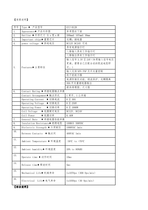
GYJ-0128 八路大功率继电器扩展控制板 开关信号放大板 开关量触点扩容控制
序号 1. 2. 3. 4.
5.
6.
7. 8. 9. 10.
Type ♦ 产品型号
GYJ-0128
Appearance♦ 产品外形图
参考图在下面
Outline ♦ 外形尺寸 长 x 宽 x 高
200mmX 107mmX 30mm
Important chips♦ 重要芯片
光耦;继电器
power voltage ♦ 供电电压
DC12V DC24V 可选
具有电源指示灯
八路输入具有工作指示灯
八路输出具有工作指示灯
输入信号 3.3V 至 24V(如果输入信号电压
更高,主要特征
可。)
输入支持 NPN PNP 及开关量控制
抗干扰能力强
电源防接反功能、续流保护、光耦隔离
30A 开关量继电器输出
0 至 1000W
Coil Voltage ♦ 线圈额定电压
DC12V、DC24V
Coil Power ♦ 线圈功率
0.46W
General Date ♦ 单继电器性能参数
Insulation Resistance♦ 绝缘电阻 100MΩ 500VDC
Dielectric Strength ♦ 介质耐压 1000VAC 1min
提供原理图、尺寸图
Contact Rating ♦ 单继电器触点参数
Contact Arrangement♦ 触点形式
1 常开、1 公共端
Operating Current ♦ 切换电流
0 至 30A
Operating Voltage ♦ 切换电压
0 至 250V
Operating Power ♦ 切换功率
二代8路时间继电器说明书

二代8路时间继电器说明书1.产品特点:多种工作模式:定时器: 可设置99个时段:每天的xx时xx分xx秒—xx时xx分xx秒 输出xx路;星期日一二三四五六,哪几天是工作日,可任意选定;输出xx路,可选择单路输出,那么xx路是十进制表示的单路,也可选择多路输出,那么xx路是十六进制表示每一路继电器状态,对应为0的位表示关,对应为1的位表示开。
计时器: 可设置与北京时间无关的一系列延时动作,可上电启动或按键启动,可循环0000-9999次或无限循环;当您需要多个不同时序的延时动作序列时,可以设置多达29组的延时系列数据,方便快速调用;每步的动作也可选择单路输出或多路输出,单路输出在轮流开启应用中有优势,多路输出在多路状态切换应用中有优势;控制精度高达0.01秒;定+计: 即定时器+计时器模式,可在定时器模式下调用计时器数据组,当您需要复杂的定时功能,该模式可大大简化设置。
2.接线说明:控制器供电:内部采用高频DC-DC降压,供电电压10-26VDC电源均可;接线如下图所示,配套卖的24V开关电源V+,V- 与控制器的V+,V- 连接,电源的L,N分别接火线和零线; 负载供电:负载通常与控制器分开供电,特别是负载与控制器供电电压不同是,一定要分开供电;负载电压范围为0-220VAC,如下图,当负载为220VAC电磁阀或交流接触器时,负载V+便为火线,负载V-便为零线,当负载为24V电磁阀时,负载V+便为+24V,载V-便为GND。
继电器规格:采用HF3FF,提供常开、常闭输出,最大切换电压:277VAC/30VDC,最大切换电流:10A;外接按键: 每路用一个按键接到V-,按一下触发,IN1—IN8分别启动01—08组计时器数据运行;具体执行什么功能,可通过设置相应的计时器数据实现。
ADC 功能暂时不支持,+5V 可以输出小于100mA 的+5V 电源。
3. 尺寸说明:145*90*40mm4. 功能设置:4.1按键功能:工作状态下,各按键功能定义:“设置”键: 进入设置状态; “删除”键: 刷新屏幕;“插入”键: 启动/暂停运行当前显示计时器数据; “-”键: 启动01组; “>”键: 启动02组; “<”键: 启动03组;“+”键: 计时器复位到01组停止状态;“<<”“>>”键: 上下翻页查看当前计时器数据或定时器数据; 设置状态下下,各按键功能定义:“<<”“>>”键: 上下翻页查看当前计时器数据或定时器数据; “<”“>”键: 左右移动设置光标;“+”“-”键: 光标所指数据递增/递减,输入设置数据; “删除”键: 删除当前显示页数据; “确认”键: 在当前显示页前插入一页; 在上电显示软件版本状态下下,各按键功能定义:“删除”键: 可清空所有定时器和计时器数据,恢复为出厂状态。
GYJ-0136_8路输入输出(NPN输入型)产品使用说明书
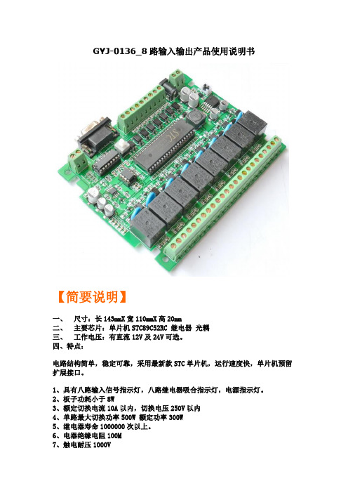
GYJ-0136_8路输入输出产品使用说明书【简要说明】一、尺寸:长143mmX宽110mmX高20mm二、主要芯片:单片机STC89C52RC 继电器光耦三、工作电压:有直流12V及24V可选。
四、特点:电路结构简单,稳定可靠,采用最新款STC单片机,运行速度快,单片机预留扩展接口。
1、具有八路输入信号指示灯,八路继电器吸合指示灯,电源指示灯。
2、板子功耗小于8W3、额定切换电流10A以内,切换电压250V以内4、单路最大切换功率500W 额定功率300W5、继电器寿命1000000次以上。
6、电器绝缘电阻100M7、触电耐压1000V8、继电器最大吸合时间15mS 毫秒9、继电器最大释放时间5mS 毫秒10、工作温度-40度至+70度11、工作湿度40% ~ 80%RH12、8路光电隔离输入,8路光电隔离输出13、8输入低电平有效(即:NPN输入)14、8路输出开关量输出(即:干接点输出)15、具有MAX232通讯和RS485通讯两种模式可选。
16、单片机所有IO口都引出,客户可以自己编程扩展功能17、可以选择使用外部EEPROM 作为存储单元18、电路具有,防反接保护、过流保护、续流保护、压敏保护等19、单片机可以自行更换,可以选择替换型的STC系列单片机20、我们提供电路相关的,原理图、例程、开发环境、下载软件等相关资料适用场合:工业控制、产品开发、项目设计,自动化改造等【标注说明】【接线说明】【输入控制设备】【输出控制设备】【输出举例说明】【输出举例说明】(开关量输出、干接点输出)【专业下载线接线说明】【串口通信说明】也可以通过串口下载【485通信说明】【MAX232与485通信切换说明】【扩展接口说明】(我们会在陆续增加、模拟量输入模块、电流模块、电压模块、无线模块、数码管显示模块、液晶模块、按键模块、PWM模块、模拟量输出模块、wifi模块、CAN模块、IP 模块等等。
)【原理图】(提供PDF格式的原理图及PCB图)更清晰免费提供与此工控板有关的:资料、例程、原理图芯片资料、软件。
8路晶体管接点开关量输出卡(XP362)

型号
XP363
卡件电源
5V供电电源
5VDC0.3V,Imax<60mA
24V供电电源
24VDC0.5V,Imax<25mA
输出回路
通道数
8路
信号类型
干触点输入Leabharlann 共地)逻辑“ON”输入<1kΩ
逻辑“OFF”输入
>100kΩ
隔离方式
光电隔离,统一隔离
隔离电压
500VAC 1分钟(现场侧与系统侧)
8
XP362是智能型8路无源晶体管开关触点输出卡,可通过中间继电器驱动电动执行装置。采用光电隔离,不提供中间继电器的工作电源;具有输出自检功能。
技术指标
型号
XP362
卡件电源
5V供电电源
5VDC0.3V,Imax<60mA
24V供电电源
24VDC0.5V,Imax<20mA
输出回路
通道数
8路
信号类型
晶体管开关触点(OC)
逻辑“0”输出阀值
最大漏电流小于0.1mA
逻辑“1”输出阀值
输出晶体管压降小于0.3V
负载能力
每点50mA(24V,吸收电流),每卡400 mA
配电方式
卡件不提供24V电源,需外配
隔离方式
光电隔离,统一隔离
隔离电压
500VAC 1分钟(现场侧与系统侧)
3
XP363卡是8路数字量信号输入卡,该卡件能够快速响应干触点输入,实现数字信号的准确采集。本卡为智能型卡件,具有卡件内部软硬件(如CPU)运行状况在线检测功能(包括对数字量输入通道工作是否正常进行自检)。
- 1、下载文档前请自行甄别文档内容的完整性,平台不提供额外的编辑、内容补充、找答案等附加服务。
- 2、"仅部分预览"的文档,不可在线预览部分如存在完整性等问题,可反馈申请退款(可完整预览的文档不适用该条件!)。
- 3、如文档侵犯您的权益,请联系客服反馈,我们会尽快为您处理(人工客服工作时间:9:00-18:30)。
M281是8路数字量输入(DI)和1路数字量输出(DO)采集控制设备,DO可以输出常开(NO)、常闭(NC)两种状态。
采用标准的Modbus TCP通讯协议,可以通过TCP/IP网络远程采集数字量数据。
本产品还提供一个RS485扩展接口,方便、灵活的级联方式,能够支持最多16级级联,使得MD44,MDIA,MDVA,MDI8,MDV8,MD82,MD88,MD16等RS485采集模块能够通过最低成本实现网络接入,并实现各种数字量、模拟量的组合扩展采集。
提供5年质保服务。
特点:
→8路数字量输入;
→1路数字量输出;
→I/O与系统完全隔离;
→采用Modbus TCP通讯协议;
→RS485接口可作为扩展接口,连接MD44,MDIA,MDV A,MDI8,MDV8,MD82,MD88,MD16等模块;
→电源具有良好的过流过压、防反接保护功能;
→丰富的指示灯,全面查看状态,及时排查故障;
→安装方便;
1.2技术参数
数字量输入接口
DI 8路干接点输入
DI保护过压小于240V ,过流小于80mA 数字量输出接口
DO 1路C型继电器2A 30VDC 1A 125V AC
DO有保护防雷600W, 过压小于60V,过流小于500mA
串口参数接口类型RJ-45
速率10/100M自适应
通信协议Modbus TCP
嵌入协议ARP,ICMP,IP,TCP,UDP,DHCP,DNS 设置方式设置程序
串口通信参数波特率9600
数据位8
奇偶效验无
停止位 1
流量控制无
地址1-255
串口保护
串口ESD保护 1.5KV
串口防雷600W
串口过流,过压小于240V,小于80mA
电源参数
电源规格9-24VDC (推荐12VDC) 电流200mA@12VDC
功耗小于2W
浪涌保护 1.5kW
电源过压,过流60V,500mA
工作环境
工作温度、湿度-25~85℃,5~95%RH,不凝露
储存温度、湿度-60~125℃,5~95%RH,不凝露其他
尺寸72.1*121.5*33.6mm
保修5年质保
M281外观。