MANUEL MORFI纤维分析仪用户手册
阿尔法拉維篩滤器控制系统说明说明书

yes yes, complete 2-way
(modbus) 1-4 filters
yes yes, complete 2-way
(modbus) multiple filters
Control systems available for use with Alfa Laval Filter (ALF) installations
Control makes the difference Well-designed control technologies have a significant effect on the quality and costs of many of the processes involved in operating ALF Filter installations. The next-generation 2Touch controls package from Alfa Laval is now available as one of the three standard control options for ALF Filter equipment.
ALF Basic Control Basic, age that ensures optimum operation and alarm handling.
ALF SmartPanel Add-on for the basic control package to provide display of operating data and trend curves on a 7-inch touch screen.
Communication to SCADA Typical use
(完整word版)罗斯蒙特质量流量计操作说明
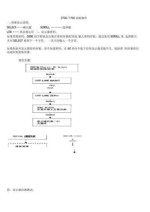
2700/1700面板操作一.屏幕显示说明:SELECT——确认键SCROLL ------- 选择键LED ---- 状态指示灯二。
显示器密码:如果需要密码,CODE的字样就会出现在密码屏幕的顶部.输入密码时候,通过使用SCROLL来选择数字,并用SELECT移到下一个字符,一次只好输入一个字符。
如果你面对显示器密码屏幕,却不知道密码,在60秒内不按下任何显示器光敏开关。
则此密码屏幕将自动退回到初始屏幕。
调零步骤:四。
显示器回路测试:TEST <>K。
则试成功》ISe-lectI1-0-CtI ScrollTEST FAIL《测困失例、五. Set MA01Set MA024 mA12 mA20 mASe eelScroll3e eel正码?二>SelectScrollOFF-LINE SIMSelectScrollScroll1 KMzIDKHzSclent读取接受设餐的输出HPYesSst D01Set D02SelectScrollOHOFP阱I M]读取接克设备的箍出致T回路测试成功女%,人出?狂.停止历具ScrollExh检登回率接线排除输出故慎显示器查看报警:LED指示灯状态及报警查看状态指示灯的状态报警优先级魄色无报警-正常运行模式鼻电闪姆”已改正但尚未信认的状态黄色已偏认的低强度报警黄色闪探⑴未稳认的做强度报警虹笆己碉认的高强度指警红色闪峭'未询认的高强虚报警11)如果报警菜单被禁止,则无沫箱认报警,在这种情况下.状态指示LEim不再闪保工报警按照报警队列中的优先级排列,要查看队列中某指定报警:L同时按下配Ml和Select按钮,当屏幕上出现"EE ALARM'」札松开按钮“ 参阅图7-1.2 .按Select按钮,3 .如果屏幕上交替出现“AGK ALL”时,则按配FQ11按钮,4 .如果屏幕上出现"0 ALARN” ,则到第6步,5,按配ell按钮查看队列中的每个技警.要了解显示帚显示的报警代码的含义请参阅翦1QJ1幸节,6,按Scroll按钮直到解幕上出现“EXIT” ”7.按Select按祗六.管理累积量和库存量:(完整word 版)罗斯蒙特质量流量计操作说明宫动/停止所有累租值和质存量⑵进行酬重副可定翻值出现空位七:测量单位设置:SELECT+SCROLL 按 4 秒 ----- ► SEE ALARM ---- ► [SCROLL] ---- ►OFFLINE MAINTAIN -------- ► [SELECT]- ..... > [SCROLL] ----- ►CONFIG ----- ► [SELECT] ---- ► MASS ------- [SELECT] ------- ►SELECTI 如果有需求.输入密码SELECTSELECT如果有需求,输入密码SELECTSELECT复位!特定累积值⑴深部翻屏直到特定累积值可以按SCROLL选择你要的单位> 选定后按SELECT按SCROLL 直到出现EXIT ----- ► [SELECT]体积单位和密度单位设置和上述步骤相同八量程设置(LRV URV)[SELECT+SCROLL] 按 4 矛秒/ SEE ALARM ------- ► [SCROLL] --- ►OFFLINE MAINTAIN --------- ► [SELECT^ ------ ►继续按SCROLL 直到出现MAO1[SELECT] ----------------------------- k SRC MAO1 ------ k [SELECT]MFLOW ---- ► [SELECT]----- SRC MAO1 ——[SCROLL]4 MAO1 ----- ►输入最小量程------ ►[SCROL L+SELEC T] 4 MAO1 ------- ► [SCROLL] ------ ►——20HMAO1 ----------- ►[SELECT] 输入最大量程------ ►[SELECT+SCROLL]--------------- > 20 MAO1>[SCROLL]EXIT ---- ^ 按SELECT 退出.其他量程设置和上述步骤相同。
FURUNO IF-NMEA 操作员手册说明书

OPERATOR'S MANUALINTERFACE UNITIF-NMEASC MODELwww.furuno.co.jpIMPORTANT NOTICES• This manual is intended for use by readers with a solid knowledge of English.• No part of this manual may be copied or reproduced without written permission.• If this manual is lost or worn, contact your dealer about replacement.• The contents of this manual and equipment specifications are subject to change without notice.• Store this manual in a convenient place for future reference.• FURUNO will assume no responsibility for the damage caused by improper use or modification of the equipment (including software) by an unauthorized agent or a third party.• When it is time to discard this product it must be done according to local regulations for disposal of industrial waste. For disposal in the USA, refer to the Electronics Industries Alliance (http:// /).SAFETY INSTRUCTIONSSAFETY INSTRUCTIONSTABLE OF CONTENTS FOREWORD (v)SYSTEM CONFIGURATION (vi)1.MOUNTING (1)1.1Equipment List (1)1.2Mounting Procedure (1)2.WIRING (2)3.ADJUSTMENTS (4)3.1LEDs and Equipment Status (4)3.2Setting Up NMEA Ports (5)3.3Heading, Pitch and Roll Offsets (8)4.OPERATION (9)5.MAINTENANCE, TROUBLESHOOTING (10)5.1Preventive Maintenance (10)5.2Replacing the Fuse (11)5.3Troubleshooting (11)5.4Self Test (12)5.5Memory Clear (13)SPECIFICATIONS.....................................................................................................SP-1 OUTLINE DRAWING...................................................................................................D-1 INTERCONNECTION DIAGRAM................................................................................S-1FOREWORDA Word to the Owner of the IF-NMEASCCongratulations on your choice of the FURUNO IF-NMEASC Interface Unit. We are confident you will see why the FURUNO name has become synonymous with quality and reliability.For 60 years FURUNO Electric Company has enjoyed an enviable reputation for quality marine electronics equipment. This dedication to excellence is furthered by our extensive global network of agents and dealers.This equipment is designed and constructed to meet the rigorous demands of the marine environ-ment. However, no machine can perform its intended function unless installed, operated and maintained properly. Please carefully read and follow the recommended procedures for installa-tion, operation and maintenance.Thank you for considering and purchasing FURUNO equipment.FeaturesThe IF-NMEASC is a dedicated interface unit for the SC-30 Satellite Compass. It receives NMEA 2000®* format heading, pitch, roll and GPS position data from the SC-30, converts them to NMEA 0183 format data and outputs the converted data to external equipment.• Input port: One NMEA 2000 format port• Four output ports: NMEA 0183x2, AD-10x1, Analog (pitch and roll)x1• Offsets for heading, pitch and roll*: NMEA 2000 is a registered trademark of the National Marine Electronics Association USA.SYSTEM CONFIGURATION1.MOUNTING1.1Equipment List1.2Mounting ProcedureWhen choosing a mounting location for the unit, keep the following points in mind:• Select a location where shock and vibration are minimal.• Locate the unit away from places subject to rain or water splash.• Keep the unit away from exhaust pipes and vents.• Locate the unit out of direct sunlight because of heat that can build up inside its cabinet.• The location should be well ventilated.• Observe the maintenance space mentioned in the outline drawing at the back of this manual and the compass safe distances in the safety instructions.• Fix the unit with four φ3x10 self-tapping screws (supplied).NameType Code No.Qty RemarksInterface Unit IF-NMEASC -1InstallationMaterials CP20-03001001-023-400 1 set • Cable ties (CN-150N, 12 pcs.)• Self-tapping screws (φ3x10, 4 pcs.)Spare PartsSP20-01301001-019-8001 setFuse FGMB 125V 2A (3 pcs.)2.WIRINGOpen the IF unit with your hands, detach the shield cover and connect external equipment, refer-ring to the illustration below and the interconnection diagram. Cables are mainly connected to the unit with WAGO connectors. See the instructions below for how to attach wiring to the connectors. The opener for the WAGO connectors is attached to the inside of the inner cover. Fix cables to their respective cable posts with cable ties (supplied). Run a ground wire (IV-2.0sq., local supply) between the ground terminal and ship's grounding bus. Supply power from breaker on mains switchboard.P o w e r c a b l eJ 8 (A n a l o g )J 7 (S C -30 S e n s o r )J 5 (N M E A 0183)J 4 (N M E A 0183)J 3 (A D -10)G r o u n d t e r m i n a lPower cable: AWG 16-20, and diameter less than 10 mm (JIS* cable DPYC-1.5 or equivalent)Cable postRecommended Cables2. WIRING Cable construction3.ADJUSTMENTS3.1LEDs and Equipment StatusThe six LEDs above the heading indication light, flash or go off according to equipment status.LED state and equipment statusLED LED state and equipment statusGPS ON: Both GPS antennas in the SC-30 are receiving from five or more satel-lites.OFF: One of the GPS antennas is receiving from 3 or fewer satellites. OUTPUT ON: All data is output from the SC-30 normally.Flashing: Motion (heading, roll, pitch) is output (heave is fixed at 0, positionand speed are normal) by dead reckoning.OFF: Heading output is stopped.PROCESSING ON: GPS processor is functioning properly.Flashing: Initializing for GPS.OFF: Not enough satellites received.SENSOR1ON: Rate gyro normal on all three axes.OFF: Rate gyro error.SENSOR2ON: Acceleration sensor normal on all three axes.OFF: Acceleration sensor error.CR33Flashing: Valid NMEA 2000 data is input.ON: No valid NMEA 2000 data is input.OFF: CPU error, or no power.3. ADJUSTMENTS3.2Setting Up NMEA PortsPorts J4 and J5 output data in NMEA 0183 format. Select the data to output from those ports, along with baud rate and output interval. The default settings are as shown in the table below.Default settings for ports 2 and 31.Grasp the cover at its right and left sides, pull the cover outward slightly and then lift the coverto remove it.2.Open the inner cover and turn on the power.On the circuit board, find the heading indication, several LEDs, and four operating buttons. The Heading LED is lit.3.Push the [Menu/Cancel] button several times to light the Sentence LED on the Port 2 line.4.Push the [Enter] button. The Sentence LED starts flashing and the sentence currently select-ed to output from port 2 is shown with a numeric. See the illustration below for numeric and data sentence.5.Push the [+] or [-] button to display the numeric corresponding to the data sentence you wishto output.6.Push the [Enter] button. The sentence LED stops flashing.Port no.SentenceBaud rate (bps)Tx interval (ms)J4 (Port 2)HDT (Heading)4800100J5 (Port 3)ATT (Heading, pitch, roll)HVE (Heave)3840025OUTPUT PROCESSING03OUTPUT PROCESSING0033. ADJUSTMENTS7.Push the [Menu/Cancel] button to light the Bps LED on the Port 2 line.8.Push the [Enter] button. The Bps LED starts flashing and the current bps setting appears.9.Push the [+] or [-] button to select desired baud rate. The choices are 4800, 9600, 19200 and38400 (bps).10.Push the [Enter] button. The bps LED stops flashing.11.Push the [Menu/Cancel] button to light the Output interval LED on the Port 2 line.12.Push the [Enter] button. The Output Interval LED starts flashing and the current output intervalsetting appears.OUTPUT PROCESSING003OUTPUT PROCESSING003OUTPUT PROCESSING003. ADJUSTMENTS13.Push the [+] or [-] button to select desired output interval, referring to the table below.14.Push the [Enter] button. The output interval LED stops flashing.15.Set up Port 3 similar to how you did Port 2.16.Close the inner and outer covers.Sentence numberSentenceOutput interval (ms)4800 bps9600 bps19200 bps38400 bps1HDT 100, 200, 1000, 200025, 100, 200, 1000, 20002HDG 100, 200, 1000, 200025, 100, 200, 1000, 20003HDM 100, 200, 1000, 200025, 100, 200, 1000, 20004ATT, HVE 200, 1000, 2000100, 200, 1000, 200025, 100, 200, 1000, 20005VTG, GGA, ZDA 1000, 20006RMC, ZDA 1000, 20007ATT, HVE 200, 1000, 2000100, 200, 1000, 200025, 100, 200, 1000, 2000GGA, VTG, ZDA1000(<1000), 20001000(<1000), 20008HDT 100, 200, 1000, 200025, 100, 200, 1000, 2000RMC, ZDA1000(<1000), 20003. ADJUSTMENTS3.3Heading, Pitch and Roll OffsetsTurn on the IF unit and wait approx. three minutes for the satellite compass to settle. Then, check that heading, pitch and roll data are reasonable. If not, open the unit and enter appropriate off-set(s).1.Open the cover, referring to step 1 in the previous section for the procedure.2.Open the inner cover.On the circuit board, find the heading display, LED set, and operating buttons. The Heading LED is lit3.Push the [Menu/Cancel] button to light the applicable Offset LED (Heading, Pitch, or Roll) andpush the [Enter] button. The selected LED starts flashing and the display shows current offset for item e the [+] or [-] button to set offset. (You can push and hold down those buttons to speed upthe rate of incrementation.)Range of offsetHeading: ±6°Pitch, Roll: ±10°5.Push the [Enter] button to finish. The display shows current heading, pitch or roll indicationwith offset applied. The selected Offset LED stops flashing.6.Close the inner and outer covers.OUTPUT PROCESSING034.OPERATIONNormally, no operation is required except to power the unit (from the switchboard). The ST-BY LED on the cover is ON, OFF or flashing according to equipment state.Flashing: NMEA 2000 data is inputON: NMEA 2000 data is not inputOFF: Power loss, blown fuse, operation error5.MAINTENANCE, TROUBLE-SHOOTINGThis chapter provides the information for keeping your unit in good working order.5.1Preventive MaintenanceRegular maintenance is important for good performance. Following the procedures in the table be-low will help maintain performancePreventive maintenanceItem Check point RemedyReplace damaged cables.Cabling Visually check cabling forsigns of wear and damage.Ground Check ground wire.Check that ground wire is tightly fastened.Check ground point for corrosion.Cover Cleanliness of cover.Dust can be removed with a soft cloth. Do not usechemical based cleaners to clean the cover, as theycan remove paint and markings and deform the cov-er.5. MAINTENANCE, TROUBLESHOOTING5.2Replacing the FuseThe 2A fuse inside the unit protects it from overcurrent and equipment fault. If the power cannot be turned on, have a qualified technician check the fuse. If the fuse has blown, find out the cause before replacing it. If it blows again, contact your dealer for advice.5.3TroubleshootingThis section provides simple troubleshooting procedures which the user can follow to restore nor-mal operation. If normal operation cannot be restored, do not attempt to check inside the equip-ment. There are no user-serviceable parts inside.Simple troubleshooting proceduresItem TypeCode No,FuseFGMB 125V 2A PBF000-157-479-10Symptom Possible troubleRemedyPower cannot be turned on• Power at switchboard is turned off.• Disconnected or damaged power cable.• Blown fuse.• Check if power is on at switchboard.• Check if power cable is disconnected or damaged.• Have a qualified technician check thefuse.Data is not received from SC-30• Signal cable between the SC-30 and this equipment is dam-aged or disconnected.• SC-30 is no received satellite signal.• Check if sensor cable is disconnect-ed or damaged.• See the SC-30's operator's manual. Data is not received at external equip-ment• Disconnected or damaged in-terconnection cable.• Output settings may be incor-rect.• Check if cable is disconnected or damaged.• Have a qualified technician check the settings.Heading, pitch or roll data is not correct • Offsets entered in this equip-ment may be incorrect.• Have a qualified technician check the settings.5. MAINTENANCE, TROUBLESHOOTING5.4Self TestThe self tests check the equipment for proper operation.Self test 1This test checks the two GPS receivers, output circuit, processor and two sensors for proper op-eration.1.Remove the cover and shield cover from the equipment.2.Press the [Menu/Cancel] button several times to show "- - -.1" on the display. The LED lampsone by one in order, the Output Interval LED in the Port 3 line, and then the equipment goes into the test mode.3.Press the [Enter] button, and the test proceeds as below.• GPS receivers are checked. The GPS lamp lights if the receivers are normal.• Communication between this equipment and the SC-30 is checked. The OUTPUT LED lights if normal.• The CPU memory access is checked. THe PROCESSING LED lights if normal.• The rate gyro is checked. The SENSOR1 LED lights if normal.• The acceleration sensor is checked. The SENSOR2 LED lights if normal.When the test is finished, the nine LEDs below the display flash, and then the display shows "End.1".4.Press the [Enter] button to return to self test 1.5. MAINTENANCE, TROUBLESHOOTING Self test 2This test checks this unit's processor and output for proper operation.1.With the display showing " - - - .1", push the [Menu/Cancel] button. The display shows "- - - 2".2.Press the [Enter] button to start the test.If the results are normal all LEDs light. Then, the nine LEDs below the display flash and the display shows "End.2".3.Press the [Enter] button to return to the self test 2 display.5.5Memory ClearThe memory can be cleared to restore the default settings for the NMEA ports. Note that offsets are not cleared.1.Hold down the [Menu/Cancel] button together with the [+] button until the display shows "-CLR". At this time all Status and Settings LEDs are on.2.Press the [Enter] button to clear the memory and restore all default settings. "END C" appearsupon completion.3.After the memory is cleared, press the [Menu/Cancel] button to show the heading.5. MAINTENANCE, TROUBLESHOOTING This page is intentionally left blank.FURUNO IF-NMEASC SPECIFICATIONS OF INTERFACE UNITIF-NMEASCPORT1 INPUTNMEA 2000*, for data I/O between FURUNO satellite compass SC-30* NMEA 2000 is a registered trademark of the Nationa l MarineElectronics Association.2 OUTPUTPORTNMEA 0183: Two ports (HDT, HDG, HMD, ATT*, HVE*, VTG, GGA,RMC, ZDA)* ATT (heading, pitch, roll) and HVE (heave) are FURUNOproprietary sentences.AD-10: One portAnalog: One port (pitch, roll)3 NMEA 0183 OUTPUT INTERVALHDT, HDG, HDM, ATT, HVE: 25ms, 100 ms, 200 ms, 1 s, 2 sVTG, GGA, RMC, ZDA: 1 s, 2 s4 POWERSUPPLY12-24 VDC: 1.0-0.6 ACONDITIONS5 ENVIRONMENTAL5.1 Ambient Temperature -15°C to +55°C5.2 Humidity Less than 95% at 40°C5.3 Waterproofing IP205.4 Vibration - From 2 Hz to 5 Hz to up to 13.2 Hz with an excursion of ±1 mm ±10%-13.2 Hz to 100 Hz with a constant maximum acceleration of 7 m/s2 COLOR6 COATINGN2.51This page is intentionally left blank.The paper used in this manualis elemental chlorine free.9-52 Ashihara-cho,Nishinomiya, 662-8580, JAPAN。
海南曼姆全系产品介绍说明书

Heinemann®GJ1P Series Circuit BreakersDESCRIPTIONOptional Low-Voltage Shunt for Current MeteringEaton Corporation’s Cutler-Hammer series of Heinemann GJ1P breakers offer high quality circuit protection for DC applications from 100 to 1200 Amperes.Their precisely tailored time delays and ability to interrupt high currents makes them ideally suited for critical applications. On overloads exceeding 1000 – 1400% of rating, there is no intentional time delay and the breaker interrupts currents of as much as 25,000 A at 65V DC.An optional shunt (25 or 50millivolt full scale) permits metering of current. Since the shunt output is low voltage,light-gauge wiring can be used from shunt to meter.Indication may be displayed inpercent, watts, safe/danger or other dial calibrations. In addition, the busbar is available in two versions:Standard Size and Reduced Size. Contact your Eaton Sales Representative for more information.Precision Current Equalization (PCE) Circuit BreakersGJ1P breakers rated 250 to1200 A are built in parallel construction. Conventional parallel pole breakers can experience uneven current distribution because of variations in internalresistances. This condition can result in nuisance tripping since the higher current in one parallel branch has the same effect as an overload on the sensing element in that branch. Proprietary Precision Current Equalization (PCE)circuit breakers, on the other hand, allow for differences in internal resistances byautomatically distributing the current equally through the parallel current sensing elements, minimizing the danger of nuisance tripping.The UL listed series GJ1P (UL489) models are available in a choice of fast, medium or slow response times to accurately match load conditions. They can be ordered in “series trip ”, “mid-trip ” and “switch only ”constructions and are available front- or back-mounted, front- or back-connected, with optional auxiliary switches for signaling.HYDRAULIC-MAGNETIC BENEFITSThe magnetic/hydraulic load-sensing and time delaymechanisms used in GJ1P breakers are insensitive to changes in ambient or enclosure temperature.Therefore, GJ1P circuitbreakers are suited for service conditions encountered in telecommunications,transportation, air conditioning and other outdoor or “heat-loaded ” equipment.SPECIFICATIONSStandard Current Ratings:100, 125, 150, 175, 200, 225,250, 300, 350, 400, 450, 500,600, 700, 800, 900, 1000,1100, 1200 A.Standard Maximum Voltages:160V DC up to 700A65V DC from 701 to 1200A Breakers will be labeled with standard maximum (UL) voltage unless otherwise specified.Special Current Ratings:Any integral rating between 100and 1200 A DC. Consult factory for ordering information and metering shunt restrictions.Interrupting Capacities:UL Listed:10,000 A @ 160V DC 25,000 A @ 65V DC Non-UL:14,000 A @ 160V DC.Operating Temperature Range:-40°C to +85°C.Approximate Weight:1-pole (100-225A) 1.13kg (2.5lbs)2-pole (250-400A) 2.27kg (5lbs)3-pole (450-700A) 3.40kg (7.5lbs)4-pole (701-800A) 4.54kg (10lbs)5-pole (801-1000A) 5.67kg (12.5lbs)6-pole (1001-1200A) 6.80kg (15lbs)Weight may vary based on shunt and busbar.APPROVALSUL Listing:GJ1P breakers are UL listed per UL489. For CSA certification,consult application engineering.Description . . . . . . . . . . . . . .2Specifications . . . . . . . . . . . .2Approvals . . . . . . . . . . . . . . .2Time Delay Characteristics . . .3Dimensions . . . . . . . . . . . .4-5How to Order . . . . . . . . . . .6-7Additional Products. . . . . . . . .8TABLE OF CONTENTS PageHEINEMANN ®CIRCUIT BREAKERSGJ1P Series Circuit Breakers(100-1200 Amperes DC)2Heinemann is a registered trademark of the Eaton Corporation, Commercial Controls Business Unit.100150.01.001.1110100100010,000200300400500600700800900100011001200125C u rv e 1C u rv e 2C u rv e 3Current – Percent of Ampere RatingT r i p T i m e – S e c o n d sDC CURVES100150.01.001.1110100100010,000200300400500600700800900100011001200125Current – Percent of Ampere RatingT r i p T i m e – S e c o n d sINSTANT DELAY DC CURVE PPERCENT OF RATED CURRENT VS. TRIP DELAY AT 25ºCTIME DELAYCHARACTERISTICSTime delay, in all models,is inversely proportional to the magnitude of the overload, adjusting automatically to limit transient power to the load. On overloads exceeding 1,000 –1,400%, the circuit breaker trips without any deliberately imposed delay.Curve 1.Standard time delayis furnished unlessanother optional delay is specified. It is thepreferred characteristic for use where the load is composed of both resistive and inductive components.Curve 2.Medium time delayis for general usein mixed (inductive and resistive) circuits where the breaker rating is matched to the current carrying capacity of the mains.Curve 3.Short time delaypermits a very brief delay period before tripping.Curve P .Non-time delay breakersare available forapplications which cannot tolerate even brief transient overloads.These breakers have no time delay mechanism other than that imposed by the coil self-inductance and the inertia of the mechanism.Tripping specificationsThe time delay curves depict breaker response time vs. percent of rated load with no preloading.The function is plotted at an ambient temperature of 77°F (25°C) with the breaker in a vertical or wall-mounted position.Series GJ1P circuitbreakers will carry 100%of rated load continuously.Both time delay and non-time delay breakers may trip between 101%and 125% of rated load,and must trip at 125%and above.3% (sec)Delay 100%125%200%400%600%800%1000%Delay Max.1no trip 1100150206 1.7.065Delay Min.1no trip 110224 1.1.01.008Delay Max.2no trip 110153.8.28.055Delay Min.2no trip 12 2.5.5.18.01.008Delay Max.3no trip 10.8.19.08.047.038Delay Min.3no trip.44.13.03.015.01.008STANDARD FRONT-CONNECTED CONSTRUCTIONWire Range #6 to 250 MCM74.59(2.938)76.20(3.000)Aux. Terminals, Male Type Molex 02-09-2101, Model 1190-T(See Illustrations for Combinations)Shunt Terminals, Female TypeMolex 02-09-1101, Model 1189-T37.69(1.484)42.84(1.687)0.99 (0.390)71.42(2.812)#10-32 Inserts (4 Places)38.10(1.500)19.05(0.750)19.05(0.750)6.35 ± 0.38(0.250 ± 0.156)6.35 ± 0.38(0.250 ± 0.156)Panel Mounting Hole Distance for #10-32LINELOAD 75.38(2.968)5.53(0.218)59.91(2.359)32.13(1.266)5.53(0.219)“D ” Type Terminals as Shown180.97(7.125)41.27(1.625)4.74(0.188)58.67(2.313)41.27(1.625)41.27(1.625)263.52(10.375)29.36(1.156)7.14(0.281)78.56(3.094)59.13(2.328)28°±5°32°±5°ONOFFSee Optional Terminal ConfigurationWire Range #6to 250 MCM41.27(1.625)36.49(1.437)38.10(1.500)100 – 22 A250 – 400Width dimensions are as follows:100 – 225 38.1 (1.5)250 – 400 A 76.2 (3.0)450 – 700 A 114.3 (4.5)701 – 800A 142.4 (6.0)801 – 1000A 190.5 (7.5)1001 – 1200A228.6 (9.0)28.95(1.141)46.40(1.828)22.22(0.875)Fastener Mounted ThisSide of Bus Plate,Terminals are Front-Connected and Unit is Rear-Mounted.Fastener Mounted This Side of Bus Plate, Terminalsare Back-Connected and Unit is Panel-Mounted.60.32(2.375)7.92(0.312)3/8-16UNC -2B (4 per Unit)38.10(1.500)225.43 (8.875)Center to CenterOptional Terminal ConfigurationsHEINEMANN ®CIRCUIT BREAKERSGJ1P Series Circuit BreakersDIMENSIONSDimensions are given here only as a preliminary guide to specifying. Final engineeringdrawings should be made from the latest Heinemann drawings. Contact Customer Service Center.Tolerance:±0.79 (0.031) except where noted. For metric threads, contact Customer Service Center.DIMENSIONS APPROXIMATE IN MM (INCHES)431.75(1.250) Min.41.65(1.641) Max.19.05(0.750)7.51(0.297)7.51(0.297)7.51(0.297)16.66(0.656)Typ.29.36(1.156)29.36(1.156)48.41(1.906)48.41(1.906)67.46(2.656)67.46(2.656)38.10(1.500)38.10(1.500)38.10(1.500)38.10(1.500)19.05(0.750)19.05(0.750)19.05(0.750)22.23(0.875) Min.321.31(12.65) Max.78.96(3.109)Min. Typ.5.15(0.203)Dia. Typ.C100 – 225 A Ratings 226 – 400 A Ratings401 – 700 150A RatingsBA106.75(4.203)Typ.C LC L C L FRONT MOUNTING PANEL AND SUPPORT BRACKET115.08(4.531)76.98(3.031)38.1(1.500)38.1(1.500)71.42(2.912)5.94(0.234)Ref.5.15(0.203)Typ. Dia.65.02(2.562)59.13(2.328)(3-Pole)3PoleC L C L C L Holes Required When Breaker Is Front-Mounted2Pole1PoleAB C (2-Pole)(1-Pole)38.88(1.531)19.43(0.765)Mounting kits containing clips, brackets and necessary hardware and instructions are available (consult factory).009-18234 100 – 225 A 1.5 (1-pole wide)009-18235 250 – 400 A 3 (2-pole wide)009-18232 450 – 700 A 4.5 (3-pole wide)For 701-1200A devices, contact your Eaton Sales Representative for mounting kit part numbers.See Step (2)See Step (5)BACK MOUNTING CIRCUIT BREAKERBack mounting circuit breaker mounting instructions 1. Position circuit breaker to support brackets.2. Place mounting bracket in recess on front top portion of circuit breaker.3. Install four (4) #10-32 by 3-1/4" long screws through holes in mounting bracket and support structure.4. Install lock washer and nut on each of the screws and tighten.5. Place mounting bracket on front lower portion of circuit breaker.6. Install two (2) #10-32 by 5/8" screws through holes in mounting bracket and support structure.7. Repeat step 4.5DIMENSIONS APPROXIMATE IN MM (INCHES)NOTE: Standard size busbar is shown above. For the reduced size busbar, contact your Eaton Sales Representative for mounting dimensions.Series PrefixGJ1PSwitch (No Coil)Series Trip w/SPDT Aux. SwitchSeries Trip Series Trip and Mid-Trip Series Trip, Mid-Trip and SPST Alarm SwitchTerminal Location Back FrontInternal Circuit Metering ShuntNo Shunts Metering Shunt Metering ShuntB HCodeLocationInternal CircuitCodeDescriptionShuntCode—25mV 50mVP M N0-2-3-98-99-Series Prefix GJ1PTerminal LocationBInternal Circuit3-Metering ShuntPAdd each appropriate Number or Letter …HEINEMANN ®CIRCUIT BREAKERSGJ1P Series Circuit BreakersHOW TO ORDER — Series GJ1PTo determine your Complete Catalog Number , you must start with appropriate Series Prefix and add the appropriate Code Letters and/or Numbers as in the example below:SELECTION TABLE61Multi-pole construction – Consult factory.An auxiliary switch, if supplied, will be located in the right pole space. If the auxiliary switch is supplied in a breaker which has a metering shunt, it will be single-pole single throw (SPST). The single-pole double throw (SPDT) auxiliary switch can be supplied only in a breaker without a metering shunt.2Cannot be used on breaker containing metering shunt.3Only for breakers rated in excess of 250 A. Breakers up to 250 A without meteringshunt are available as standard GJ1 type breakers. Please consult Series GJ catalog.MarketUL-489TerminalsSolderless Connector Bus Bar ConnectionStandard Current Ratings 1AmpereTrip Curve 1123P0 – 1200(Add 0 before amp rating if less than 1000A.Example: 0700)-01-02-03-0PDescriptionCodeDEDUStandardCodeCurveCodeComplete Catalog Number: GJ1PB3-PEDU0700-02Terminal ConfigurationEUS/European ApprovalDUStandard Current Ratings 10700Trip Curves 1-024Add 0 before amp rating if less than 1000. For example: a 700A rating would bedesignated as 0700.The width of the breaker is determined by the current rating:100 – 225 A 1.5” (1-pole wide)250 – 400 A 3” (2-pole wide)450 – 700 A 4.5” (3-pole wide)701 – 800A 6” (4-pole wide)801 – 1000A 7.5” (5-pole wide)1001 – 1200A 9” (6-pole wide)5See page 3 for time delay characteristics and trip curve information.7© 2001 Eaton Corporation All Rights Reserved Printed in USAForm No. BR5401SE0002A / CSS 65322June 2001Commercial ControlsFor the Widest Selection of Circuit Protection, from 0.01 to 1200 Amperes, Look to Eaton.。
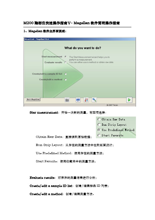
VMagellan简明操作指南
5.判断方法定义:通过设置本选项,软件可以对样品进行判断和分类显示, 点击后在弹出窗口中输入数据源、判断值等即可。
6.质控参数定义:通过本项设置,可以输入测量的质控标准,测量结束后 软件会自动判断测量是否达到质控标准,并给出 True 或 False 的判断结果。
7.数据操作栏:可以设置数据导出的内容和格式,打印的内容和格式,以 及测量完成后要立即开始的数据操作,详情请参考 Magellan 软件说明书或东胜 创新培训课件光盘。
:文件操作功能; :选项,从这里可更改文件保存默认文件夹位置;
:用户管理;
:软件版本和注册信息。 :温度控制,点击此按钮将弹出温控窗口:
填写好目标温度(至少比室温高 5 度,最高 42 度),点击 set 按 钮确认输入,点 On 按钮即可开启控温,点击 Read 按钮可读取当前仪 器内温度,点击 Off 按钮关闭控温。
4.标准曲线定义:当填写了“ST”-标准样品浓度后,就可以点击此选项, 在弹出窗口中定义标准曲线的数据源、坐标、回归方式、扩展因子、外观等设置。 设置完成后软件会自动产生一个“Conc.transforme”-浓度转换栏,并生成 一个浓度转换,在测量获得数据后,软件将根据标准曲线公式自动计算出样品的 浓度。
8.杂项栏:可以为测量填写提示信息和注解,比较有用的功能是设置数据 显示的数值格式:
根据测量要求设置即可。 有关数据处理方法的详尽说明请参考 Magellan 软件说明书或东胜创新培 训课件光盘。 测量方法创建/编辑完成后,点击窗口右下角绿色三角形“Fininsh”,在下 一窗口中保存创建/编辑过的方法。
存和打印功能将不可用,注册方法见软件说明书。注册应由 Tecan 代理商负责, 如需要注册和需要了解注册问题请联系代理商。
Master Manufacturing 无杆稀释喷头系统说明书

Most spray materials are highly corrosive. The most important aspect of long dependable service from the sprayer is a thorough cleaning immediately following each use. In addition, the residue of one type of chemical could cause an undesirable effect when a different chemical is used for a different purpose.
When selecting pressure from the tip chart, it is a good idea to try for approximately 30 PSI as this allows for an excellent nozzle pattern. At 10 PSI the pattern begins to break up and at 40 PSI you may notice some drift. Conditions of weather and terrain must be considered when setting the sprayer. Do not spray on windy days. Protective clothing must be worn in some cases. Be sure to read the chemical label carefully. Before spraying chemicals, fill the tank half full of plain water to allow familiarization with the sprayer and to prevent waste of expensive chemicals. After all calibrations have been completed, add water and chemicals to the tank. Always follow chemical manufacturer’s instructions for mixing.
Amana GCVM 97% ECM Counter Flow Furnace 商品说明书
REPAIR PARTS® nufacturing Company, L.P. ◊ 5151 San Felipe, Suite 500 ◊RP-G2001BThis manual is to be used by qualified technicians only.This manual replaces RP-G2001A.April 2015GCVM 97% ECM Counter Flow Furnace© 2014-2015 Goodman Manufacturing Company, L.P. ◊ 5151 San Felipe St., Suite 500 ◊ Houston, TX 77056GCVM970603BNAA GCVM970803BNAA GCVM970804CNAA GCVM971005CNAAImportant Information For assistance within the U.S.A. contact:Goodman Company, L.P.For assistance outside the U.S.A. contact:IndexFunctional Parts List Rev B: updates primary limit controlsIllustration and Parts......................................................................................................................................................................................................Views shown are for parts illustrations only, not servicing procedures AR - As Required NA - Not Available NS - Not Shown00000000 - See NoteQTY - Quantity Example (QTY 3) (If Quantity not shown, Quantity = 1)M - Model Example (M1) (If M Code not shown, then part is used on all Models)Text Codes:ExampleM1 - Model#1 M2 - Model#2 M3 - Model#3Expanded Model Nomenclature:Goodman Manufacturing Company, L.P. is not responsible for personal injury or property damage resulting from improper service. Review all service information before beginning repairs.Warranty service must be performed by an authorized technician, using authorized factory parts. If service is required after the warranty expires, Goodman Manufacturing Company, L.P. also recommends contacting an authorized technician and using authorized factory parts.Goodman Manufacturing Company, L.P. reserves the right to discontinue, or change at any time, specifications or designs without notice or without incurring obligations. 2Consumer Affairs DepartmentGoodman Manufacturing Company, L.P.7401 Security Way Houston, Texas 77040877-254-4729-Telephone 713-863-2382-FacsimileInternational DivisionGoodman Manufacturing Company, L.P.7401 Security Way Houston, Texas 77040713-861-2500-Telephone 713-863-2382-Facsimile 4 - 113RP-G2001BFunctional PartsPartNo:Description:20162904*PRIMARY LIMIT-TEMPERATURE CONTROL(M2)*Refer to service bulletin SF-0540130F00038AUX LIMIT - LT BLUE 120º (QTY 2)0163F00017BECKETT BURNER (QTY 3)0271F00161BLOWER SHELL & WHEEL ASSY (M3, M4)0271F00159BLOWER SHELL & WHEEL ASSY (M1, M2)0130F00393DATA, FURNACE PCB (M1)0130F00394DATA, FURNACE PCB (M2)0130F00395DATA, FURNACE PCB (M3)0130F00396DATA, FURNACE PCB (M4)0130F00010FLAME SENSOR0151M00024GAS VALVE0257F00282HEAT EXCHANGER ASSY. (M2)0257F00284HEAT EXCHANGER ASSY. (M4)0257F00311HEAT EXCHANGER ASSY. (M1)0257F00312HEAT EXCHANGER ASSY. (M3)0130F00008IGNITOR-SINI 17 SEC0130M00141INDUCTOR, 5.9 AMPS (GMPE100-4) (M3, M4)0130M00243INTERLOCK SWITCH10123529MANUAL RESET R.O.S. LIMIT (QTY 2)0131M00272MOTOR, 1 HP, SERIAL ECM (M4)0131M00270MOTOR, 1/2 HP, SERIAL ECM (M1, M2)0131M00271MOTOR, 3/4 HP, SERIAL ECM (M3)0171M00003MOTOR-ID, BLOWERPCBKF202PCB, FURNACE CONTROL20162901PRESSURE LIMIT-RED (M3)0130F00481PRESSURE SWITCH (-.1 (COL BOX))0130F00482PRESSURE SWITCH (-.17 /-.86) (M1, M2, M3)0130F00483PRESSURE SWITCH (-.17 /-.86) (M4)0130F00036PRIMARY LIMIT - PINK (M1, M4)0130M00140TRANSFORMER 120V TO 24V, 40VASPECIAL PARTS0161F00000P GOODMAN NAMEPLATEExpanded Model NomenclatureM1 - GCVM970603BNAAM2 - GCVM970803BNAAM3 - GCVM970804CNAAM4 - GCVM971005CNAARP-G2001B 3Cabinet 4RP-G2001BCabinetRef. No:PartNo:Description:Ref.No:PartNo:Description:Image 1:GASKET (QTY 2)0154F00024111GASKET (QTY 2)0154F00025121DOOR, ACCESS 17.5 PNT (M1, M2)0121F00291DG191DOOR, ACCESS 21 PNT (M3, M4)0121F00292DG191DOOR, BLOWER 17.5 PNT (M1, M2)0121F00288DG201DOOR, BLOWER 21 PNT (M3, M4)0121F00289DG201VIEW PORT BUSHING-BLOWER DOOR (QTY 2)B1392139281GASKET, DECK (M1, M2)0154F00020311GASKET, DECK (M3, M4)0154F00021311PIPE, STRAIGHT CF (QTY 2)0161F00064441PIPE GROMMETM0501301451BUTTON PLUGM0570808491BUTTON PLUGM0570806501PLUG, HOLE0161M00027521HOSE CLAMP (QTY 2)0163M00049611UNIVERSAL BUSHING UB 875B1392104741BUTTON PLUG (QTY 2)M0310345NSBUTTON PLUGM0570807NSCF DRAIN TUBE ASSY (M1, M2)0270F03125NSCF DRAIN TUBE ASSY (M3, M4)0270F03126NSCF DRAIN TUBE ASSY (M1, M2)0270F03514NSCF DRAIN TUBE ASSY (M3, M4)0270F03515NSDRAIN TRAP0161F00046NSGOODMAN NAMEPLATE0161F00000PNSSCREW-DECORATIVE (QTY 3)M0209730NSImage 2:DRAIN PART BAG ASSY CF0270F0314112BAG ASSY CF0270F0313922Expanded Model NomenclatureM1 - GCVM970603BNAAM2 - GCVM970803BNAAM3 - GCVM970804CNAAM4 - GCVM971005CNAA5 RP-G2001B Blower Assembly 6RP-G2001BBlower AssemblyRef.No:Part No:Description:Ref.No:Part No:Description:Image 1:BLOWER SHELL & WHEEL ASSY (M1, M2)0271F0015931BLOWER SHELL & WHEEL ASSY (M3, M4)0271F0016131BLOWER MOTOR GROMMET (M3, M4)A400270261MOTOR MOUNT BAND (M1, M2)0121M00038141MOTOR MOUNT BAND (M3, M4)10441601141MOTOR MOUNT ARM (M3, M4)10441501151MOTOR MOUNT ARM (M1, M2)B1376857151MOTOR, 1 HP, SERIAL ECM (M4)0131M00272181MOTOR, 1/2 HP, SERIAL ECM (M1, M2)0131M00270181MOTOR, 3/4 HP, SERIAL ECM (M3)0131M00271181TC SCREW (M3, M4)M022*******TC SCREW 1.25" (M1, M2)M025*******MACHINE SCREW (M3, M4)M0267144251MACHINE SCREW HWH 1/4-20 X 1-1/2 BZ (M1, M2)B1393323251WASHER, FLAT 1/4 ID X 1 OD (M1, M2)B1392918261WASHER-FLAT (M3, M4)M027*******KEPS NUT (M3, M4)M028*******LOCKNUT, NYLON, INSERT 1/4, 20 (M1, M2)B1393800281TRANSFORMER 120V TO 24V, 40VA0130M00140381INDUCTOR, 5.9 AMPS (GMPE100-4) (M3, M4)0130M00141391PCB, FURNACE CONTROL PCBKF202401COVER, CONTROL BOARD0161F00014411CONTROL MOUNT PANEL0121F00094461AUX LIMIT - LT BLUE 120º (QTY 2)0130F00038521SLIT LOCK WASHER (M3, M4)B1392820621CONTROL HARNESS0259F00040NS DATA, FURNACE PCB (M1)0130F00393NS DATA, FURNACE PCB (M2)0130F00394NS DATA, FURNACE PCB (M3)0130F00395NS DATA, FURNACE PCB (M4)0130F00396NS PLASTIC PLUG, 1" (2713-BLK) (QTY 4)B1392021NS POWER HARNESS HIGH VOLTAGE 0259F00041NS WIRE HARNESS-BLOWER0259F00024NS*If end bells are needed please order the following: 0131M00182 - 1/2 HP 0131M00183 - 3/4 HP 0131M00184 - 1 HPExpanded Model Nomenclature M1 - GCVM970603BNAA M2 - GCVM970803BNAA M3 - GCVM970804CNAA M4 - GCVM971005CNAA7RP-G2001B Chassis 8RP-G2001BChassisRef. No:PartNo:Description:Ref.No:PartNo:Description:Image 1:PAINTED BASE PAN-21" C (M3, M4)0121F00435DG11PAINTED BASEPAN-17.5" CF (M1, M2)0121F00427DG11DECK-BLOWER, 17.5" CF (M1, M2)0121F0042531DECK-BLOWER, 21" CF (M3, M4)0121F0043331INSULATION, HT EXCHANGER 17.5" (M1, M2)0160F0001591INSULATION, HT EXCHANGER 21" (M3, M4)0160F0001691ANGLE, DECK (M1, M2)0121F00314101ANGLE, DECK (M3, M4)0121F00315101TOP, PAINTED FURNACE 17.5" CF (M1, M2)0121F00426DG111TOP, PAINTED FURNACE 21" CF (M3, M4)0121F00434DG111ANGLE, SIDE (QTY 2)0121F00313121GASKET-FA (M1, M2)20179309151GASKET-FA (M3, M4)20179310151INSULATION-BACK 17.5" (M1, M2)0160F00012161INSULATION-BACK 21" (M3, M4)0160F00013161INSULATION, SIDE (QTY 2)0160F00018171HARNESS-WIRING0159F0005018125" PRESSURE SWITCH HOSES (M3, M4)0164M00029191PRESSURE SWITCH HOSE (M1, M2)0164M00012191HOSE-PRESSURE SW 6"0164M00019201INTERLOCK SWITCH0130M00243221ELBOW-FLUE, 17.5" CFLOW (M1, M2)0164F00003241ELBOW-FLUE, 21" CFLOW (M3, M4)0164F00004241MOTOR-ID, BLOWER0171M00003271COUPLING0161F00037281PRESSURE SWITCH (-.1 (COL BOX))0130F00481291PRESSURE SWITCH (-.17 /-.86) (M1, M2, M3)0130F00482301PRESSURE SWITCH (-.17 /-.86) (M4)0130F00483301JUNCTION BOX PLA0161F00042311JUNCTION BOX LID0161F00043331PLUG-TUBEM0326804701GASKET (QTY 2)0154F00015791GASKET (M1, M2)0154F00014811GASKET (M3, M4)0154F00016811BRACKET, DOOR SWITCH0121F00389991PRESSURE SWITCH HOSE (M3, M4)0164M00008NSExpanded Model NomenclatureM1 - GCVM970603BNAAM2 - GCVM970803BNAAM3 - GCVM970804CNAAM4 - GCVM971005CNAA9 RP-G2001B Heat Exchanger / Manifold / Gas Valve 10RP-G2001BHeat Exchanger / Manifold / Gas ValveRef. No:PartNo:Description:Ref.No:PartNo:Description:Image 1:IGNITOR-SINI 17 SEC0130F0000811GAS VALVE0151M0002421ORIFICE (QTY 3)0163F0000431FLAME SENSOR0130F0001041MANUAL RESET R.O.S. LIMIT (QTY 2)1012352951MANIFOLD (M1)0163F0000861MANIFOLD (M3)0163F0000961MANIFOLD (M4)0163F0001061MANIFOLD (M2)0163F0001461BECKETT BURNER (QTY 3)0163F0001771BRACKET-BURNER 3 (M1)0121F0045581BRACKET-BURNER 4 (M2, M3)0121F0045481BRACKET-BURNER 5 (M4)0121F0045381ORIFICE BRACKET-BURNER 3 (M1)0121F00458111ORIFICE BRACKET-BURNER 4 (M2, M3)0121F00457111ORIFICE BRACKET-BURNER 5 (M4)0121F00452111COVER, FRONT (M4)0161F00027131COVER, FRONT (M2)0161F00031131COVER, FRONT (M1)0161F00056131COVER, FRONT (M3)0161F00065131GASKET, FRONT (M1, M2)0154F00011141GASKET, FRONT (M3, M4)0154F00012141HEAT EXCHANGER ASSY. (M2)0257F00282151HEAT EXCHANGER ASSY. (M4)0257F00284151HEAT EXCHANGER ASSY. (M1)0257F00311151HEAT EXCHANGER ASSY. (M3)0257F00312151TUBE PLUGM0326804161CAP-VINYL .500A1781105231COVER, REAR (M1, M2)0121F00317261COVER, REAR (M3, M4)0121F00318261GASKET, REAR CVR (M1, M2)0154F00037271GASKET, REAR CVR (M3, M4)0154F00038271*PRIMARY LIMIT-TEMPERATURE CONTROL (M2)20162904371*Refer to service bulletin SF-054PRESSURE LIMIT-RED (M3)20162901371PRIMARY LIMIT - PINK (M1, M4)0130F00036371PRIMARY LIMIT-HEAT SHIELD0121F00439NSSHIELD, COIL (QTY 2)0121F00355NSExpanded Model NomenclatureM1 - GCVM970603BNAAM2 - GCVM970803BNAAM3 - GCVM970804CNAAM4 - GCVM971005CNAA11 RP-G2001B 。
reflexMBMLL操作说明书
reflex ’MBM II Membranbruchmelder’reflex ’MBM II Diaphragm Rupture Detector’Montage-, Betriebs- und WartungsanleitungInstallation, operating and maintenance instructionsAllgemeine SicherheitshinweiseDer ’MBM II’ Membranbruchmelder ist eine elektrische Schalteinrich-tung, die nur entsprechend den Hinweisen in dieser Anleitung einge-setzt werden darf. Die elektrische Verkabelung und der Anschluss sind von einem Fachmann nach dem gültigen EVU und VDE Vorschriften auszuführen. Vor den Arbeiten an elektrischen Bauteilen ist die Anlage spannungsfrei zu schalten.Das Missachten dieser Anleitung, insbesondere der Sicherheitshinwei-se, kann zur Zerstörung und Defekten am ’MBM II’ Membranbruchmel-der führen, Personen gefährden sowie die Funktion beeinträchtigen. Bei Zuwiderhandlung sind jegliche Ansprüche auf Gewährleistung und Haftung ausgeschlossen.Montage, Inbetriebnahme → auch Seite 2– Die Anschlüsse A1 und A2 sind spannungsfrei geschaltet.– Elektrodenrelais (3) an Wand o. ä. in unmittelbarer Nähe des Gefäßes befestigen. Vorher ist das Gehäuse abzuschrauben.– Kabelverbindungen herstellen, es stehen 4 Kabeleingänge zur Verfügung (Kabel bauseits).Liefergrenze Reflex = Klemmleiste Elektrodenrelais (3)- Klemme Min. mit Stecker 2.2 der Eletrode (2) verbinden. Dazu Stecker 2.2 abziehen, Kabel einstecken und vorher gelöste Schraube im Stecker 2.2 festziehen.- Klemme Max. (Masse) mit Erdungsblech (2.1) verbinden, vorher Kabel abisolieren.- Falls gewünscht, an die Klemmen 11, 12, 14 potenzialfreien Ausgang anschließen.- Klemmen A1 und A2 für Eingangsspannung anschließen.– Empfindlichkeit am Potenziometer (3.3) auf 20 k Ω einstellen (= Werkseinstellung).– Gehäuse anschrauben.– Zuleitungen A1 und A2 mit Spannung versorgen.Der ’MBM II’ ist jetzt in Betrieb.Betrieb → auch Seite 2Der Betrieb ist nur mit angeschraubtem Gehäuse statthaft.– Normalbetrieb : grüne LED leuchtet – Membranbruch : gelbe LED leuchtetMembranbruch kann zu vollständigem Funktionsausfall des Membran-Druckausdehnungsgefäßes führen. Bitte verständigen Sie umgehend Ihren Reflex-Servicedienst.Funktion, Voraussetzungen für die Montage → auch Seite 2– Das Membran-Druckausdehnungsgefäß muss werksseitig für die Montage des ’MBM II’ vorbereitet sein und im unteren Drittel eine Muffe Rp 1/2 (1) besitzen. Ein nachträgliches Einschweißen der Muffe ist unzulässig.– Funktion:Im Falle von Membranbruch wird durch eindringendes Wasser in den Gasraum der elektrische Kontakt zwischen Masse (Erdungsblech 2.1) und Stecker (2.2) hergestellt und ein Signal ausgelöst.Einsatzbereiche, BetriebsparameterDer ’MBM II’ wird zur Signalisierung von Membranbruch bei Membran-Druckausdehungsgefäßen in Heizungs-, Kühl- und Trinkwassersyste-men eingesetzt. Er besteht im wesentlichen aus der Elektrode und dem Elektrodenrelais.Elektrode (2)zul. Betriebstemperatur : t max ≤ 70°C zul. Betriebsüberdruck : p max ≤ 25 bar Elektrodenrelais (3)Spannungsversorgung : 230 V, 50 Hz potenzialfreier Ausgang (Wechsler) : ≤ 250 V Ansprechempfindlichkeit : 5 - 100 k Ω (am Poti einstellbar) Schutzgrad im Gehäuse : IP 65General Safety InstructionsThe ’MBM II’ diaphragm rupture detector is an electrical switchgear that may be exclusively used in accordance with the notes contained her-ein. The electrical cabling and the connection must be performed by a specialist according to the applicable EVU and VDE provisions. Prior to performing any work on electrical components, it must be ensured that the system is not alive.The non-compliance with the present instruction, in particular the no-tes on safety, may lead to the destruction and faults of the ’MBM II’ diaphragm rupture detector, to personal injuries and may affect the function. In case of the violation of such instruction, any and all claims for warranty and liability are excluded.Assembly, Commissioning → also page 2– The connections A1 and A2 are connected off-circuit.– Mount the electrode relay (3) on a wall or similar in the immediate vicinity of the vessel. Unscrew the housing in advance.– Establish the cable connections. Four cable inputs are available (cables to be provided on site).Reflex delivery limit = terminal block electrode relay (3)- Connect the min. terminal with plug 2.2 of the electrode (2). T o do so, disconnect plug 2.2, insert the cable, and fasten the previously released screw in the plug 2.2.- Connect the max. terminal (mass) with the earthing plate (2.1), strip the cable insulation in advance.- If desired, connect a floating output to the terminals 11, 12, 14. - Connect the terminals A1 and A2 for the input voltage.– Set the sensitivity on the potentiometer (3.3) to 20 k Ω (= factory setting).– Fasten the housing with screws.– Supply the feed lines A1 and A2 with power.Now, the ’MBM II’ is operational.Operation → also page 2The operation is only admissible if the housing is fastened with screws.– Regular operation : green LED is on – Diaphragm rupture : yellow LED is onA diaphragm rupture can result in the complete functional failure of the diaphragm expansion vessel. Please contact your Reflex service immediately.Function, Installation Requirements → also page 2– The diaphragm expansion vessel must be prepared on site for the installation of the ’MBM II’ and must provide of a Rp 1/2 (1) sleeve in the lower third. A subsequent welding of the sleeve is not admis-sible.– Function:In the event of a diaphragm rupture, the electrical contact between the mass (earthing plate 2.1) and the plug (2.2) is established by water penetrating into the gas space, and a signal is triggered.Application, Operating ParametersThe ’MBM II’ is used for the signalling of a diaphragm rupture ofdiaphragm expansion vessels in heating, cooling, and drinking water systems. It mainly consists of the electrode and the electrode relay.Electrode (2)permiss. operating temperature : t max ≤ 70°C permiss. operating excess pres. : p max ≤ 25 bar Electrode relay (3) Power supply : 230 V, 50 Hz floating output (change-over cont.) : ≤ 250 V response sensitivity : 5 - 100 k Ω (adjustable on potentiometer ) degree of protection in the housing : IP 65reflex ’MBM II Membranbruchmelder’reflex ’MBM II Diaphragm Rupture Detector’S I 0216A / 03 - 06 T e c h n i s c h e Än d e r u n g e n v o r b e h a l t e n T e c h n i c a l d e t a i l s s u b j e c t t o m o d i f i c a t i o nMontage- und LieferübersichtOverview of the Installation and Delivery1 Rp 1/2 sleeve on the vessel2 Electrode , with vessels which have a constant pre-set pressure sealed into the vessel sleeve (1) in the factory, otherwise enclosed for on-site installation. 2.1 Earthing plate 2.2 detachable plug2.3 Angle3 Electrode relay in the housing3.1 green LED, is on during the regular operation 3.2 yellow LED, is on during in case of a diaphragm rupture3.3 Potentiometer to adjust the response sensitivity 4 Transport protection for the electrode (2), channel section made of foamed material,remove prior to the installationKonformitätserklärungDas Elektrodenrelais ist für den Einsatz im ’MBM II’ geeignet und wird folgenden Normen gerecht:VDE 0435, VDE 0609, VDE 0110, VBG 4, IEC 158-1,IEC 255-0-20, IEC 255-3 & 6, IEC 255-8 & 17, IEC 255-22-1, IEC 255-22-2, IEC 255-5, IEC 801-4, IEC 67.1.5 1 & 18, DIN 46277, IEC 529, DIN 40050, NFC 20010 Zulassungen: UL, CSA Declaration of ConformityThe electrode relay is suited for the deployment in the ’MBM II’ and complies with the following standards:VDE 0435, VDE 0609, VDE 0110, VBG 4, IEC 158-1,IEC 255-0-20, IEC 255-3 & 6, IEC 255-8 & 17, IEC 255-22-1, IEC 255-22-2, IEC 255-5, IEC 801-4, IEC 67.1.5 1 & 18, DIN 46277, IEC 529, DIN 40050, NFC 20010 Approvals:UL, CSANetwork 230 V, 50 Hz6,4 mm x 2,5 mm, NSGAFÖU (bauseits) 6.4 mm x 2.5 mm, NSGAFÖU (on site)2.22.32.141 Muffe Rp 1/2 am Gefäß2 Elektrode , bei Gefäßen mit konstantem Vordruck werksseitig in Behältermuffe (1) eingedichtet, ansonsten beigelegt zur bauseitigen Montage. 2.1 Erdungsblech2.2 abziehbarer Stecker 2.3 Winkel3 Elektrodenrelais im Gehäuse3.1 grüne LED, leuchtet bei Normalbetrieb 3.2 gelbe LED, leuchtet bei Membranbruch 3.3 Potenziometer zur Einstellung der Ansprechempfindlichkeit4 Transportschutz für Elektrode (2), U-Profil aus Schaumstoff, vor derMontage abnehmen33.33.23.1Reflex Winkelmann GmbH + Co. KG Gersteinstraße 1959227 AhlenTelefon: +49 23 82 / 70 69-0Telefax: +49 23 82 / 70 69-588www.reflex.de。
微尔菲尔筛膜系统说明书
The life science business of Merck operates as MilliporeSigma in the U.S. and Canada.The Microfil ® filtration system is a simple and reliable solution for routine testing of raw materials, beverages and water for microbiological contamination. These tests are an important part of your quality assurance program. The standard testing method used in laboratories around the world for microbial analysis of fluids is membrane filtration. However, this method is technically demanding and requires time-consuming preparation, assembly and sterilization of the test apparatus.With our Microfil ® filtration system, you will eliminate time-consuming steps, equipment setup, waste, and autoclaving while improving the productivity of your lab. This cost-effective system uses presterilized, ready-to-use funnels and membranes on a filtration support.Benefits• No Preparation • No Washing • No Autoclaving • No Clamps • No Breakage • No Filter Wrinkling • No sample By-PassData SheetMicrofil ® Filtration SystemAn easy to use, fast and accurate system for the routine microbiological analysis of your beverages and drinking waterCulture MediaYou will find the full range of culture media (including broth and dehydrated media) on our website at /Microbiology.2Consistent RecoveriesUnlike with conventional filter holders, incompletesealing at the membrane/funnel interface is eliminated resulting in uniform recovery of organisms. The smooth hydrophobic funnel surface repels sample residues and microorganisms to ensure that any microorganisms in your sample are collected on the membrane and not lost on the funnels walls. Pleating and distortion of the wet membrane due to expansion is avoided by the design of the support. As a result, uniform contact between the membrane and the medium is achieved.Faster Filtration RatesDue to the membrane support, filtration rates withthe Microfil ® filtration system are faster when compared to traditional filtration equipment.Minimize Clean-Up, Assembly and AutoclavingReady-to-use, ultra-thin 100 or 250 mL Microfil ® funnels eliminate the need for washing and sterilizing after each test and make equipment handling easy. Packaged in convenient stacks of 25 or 30, the funnels are removed as needed from the custom designed funnel dispenser. Such vertical stacking of the funnels also optimizes lab space.A range of pre-sterilized 47 mm diameter gridded membranes are available with the Microfil ® funnels. Each membrane is individually sealed in pleated band (EZ-Pak ® membranes) or in peel back envelopes (S-Pak ® membranes). Polycarbonate membranes are also available.Easy-to-Use with No Clamps and No O-RingsThe push-fit design of the Microfil ® funnels seals tightly to manifold supports without the need for clamps or O-rings. This ensures leak-free operation and uniform microorganism recoveries.3Microfil ® Filtration System Method Advantages• Use of 47 mm gridded presterilized membranes • 100 mL and 250 mL funnels for drinking water and mineral water analysis• Hydrophobic funnel surfaces for improved recovery • Smooth interior funnel surfaces with no scratches • Lip seal to prevent membrane by-pass• Food-contact-polymer funnels, free from agents that may inhibit bacterial growth • Disposable funnels eliminate decontamination by flaming or use of alcohol • Recyclable plastic funnel material that allows for greater environmental protection • 0.45 μm membranes are certified in accordance with Standard Methods for coliform analysisUnited States• Standard Methods for the Examination of Water and Wastewater 22 edition, 2012Europe• EEC Directive 2009/54/EC of the European Parliament and of the council of 18th June 2009• EC Directive 98/83/EC, 3 November, 1998, amended version EEC directive 2015/178, relating to the quality of water intended for human consumptionWorldwideWHO Guidelines for Drinking Water Quality, 2017ISO ® RegulationsISO ® ISO 11731:2017: Water Quality Water Quality - Enumeration of Legionella ISO ® 8199:2018: Water Quality Water quality – General guidance on the enumeration of microorganisms by culture ISO ® 7899-2:2000: Water QualityDetection and enumeration of intestinalenterococci – Part 2: Membrane filtration methodISO ® 9308-1:2014: Water QualityEnumeration of Escherichia coli and coliform bacteria - Part 1: Membrane filtration method for waters with low bacterial background flora ISO ® 19250:2010: Water Quality Detection of Salmonella spp.ISO ® 26461-2:1986: Water Quality Detection and enumeration of the spores of sulfite-reducing anaerobes (clostridia); Part 2: Method by membrane filtration ISO ® 7704:1985: Water Quality Evolution of membrane filters used for microbiological analysesISO ® 16266:2006: Water QualityDetection and enumeration of Pseudomonas aeruginosa by membrane filtration ISO ® 14189:2013: Water Quality Enumeration of Clostridium Perfringens – Method using membrane filtration ISO ® 17995:2005: Water QualityDetection and enumeration of thermotolerant Campylobacter speciesRegulatory RequirementsThe Microfil ® filtration system method has been established with reference to InternationalStandards allowing biological analysis to be conducted under optimum conditions and conforms to International Standards for drinking water and mineral water.4Processing an aqueous sample using theMicrofil ®filtration system can be done in 7 simple steps:Step 2Place either an EZ-Pak ®, S-Pak ® or a polycarbonate membrane filter on the Microfil ® filtration system support.Step 3Dispense a Microfil ® funnel using the specially designed dispenser.Step 4Place the Microfil ® funnel on the support and push down to fix it firmly in place.Step 5Pour the sample into the funnel and filterby applying vacuum.Step 1Sanitize the Microfil ® filtration system support prior to processing each sample. Recommended methods include the use of alcohol or a quick flaming of the Microfil ® filtration system support steel surface.5Step 6Remove the funnel. The tweezer is stopped by a protective rim to avoid touching the filtration area.Step 7Place the membrane filter into a Petri dishcontaining solid or liquid medium and incubate.Step 8Filter support can easly be removedfor decontamination.Ordering Information150 Funnels and 150 S-Pak® MembranesEach box contains 6 x 25 (100 mL) or 5 x 30 (250 mL) sterilized Microfil® funnels and150 individually packed, sterilized 47 mm diameter gridded S-Pak® membranes, available with the following pore sizes and colors:0.2 µm white, gridded MIGSWG100MIGSWG250 0.45 µm white, gridded MIHAWG100MIHAWG250 0.45 µm white, plain MIHVWP100N/A0.45 µm black, gridded MIHABG100MIHABG250 0.7 µm white, gridded MIHCWG100MIHCWG2500.8 µm white, gridded MIAAWG100MIAAWG2501.2 µm white, gridded MIRAWG100MIRAWG250 150 Funnels and 150 Isopore® Polycarbonate Membranes0.4 μm; colorless, plain N/A MIHTTP250 Additional membranes are available - 0.4 μm; colorless, plain - 150 units - item MIHTTPMNE 150 Funnels and 150 EZ-Pak® MembranesEach box contains 6 x 25 (100 mL) or 5 x 30 (250 mL) sterilized Microfil® funnels anda band of 150 individually packed, sterilized 47 mm diameter gridded EZ-Pak® membranes, available with the following pore sizes and colors:0.2 µm white gridded MZGSWG101N/A0.45 µm white, gridded MZHAWG101MZHAWG251 0.45 µm black, gridded MZHABG101MZHABG251 0.8 µm white, gridded MZAAWG101MZAAWG251 0.8 µm black, gridded MZAABG101N/A6EquipmentEZ-Fit™ Manifold 1-place for Microfil®EZFITMIC01EZ-Fit™ Manifold 3-place for Microfil®EZFITMIC03EZ-Fit™ Manifold 6-place for Microfil®EZFITMIC06Microfil® Funnel Dispenser, for use with 100 mL funnels MIACFD101Microfil® Funnel Dispenser, for use with 250 mL funnels MIACFD201EZ-Pak® Dispenser Curve EZCURVE01EZ-Stream® Vacuum Pump for Liquid Transfer EZSTREAM1Microfil® filtration system pump head for Merck vacuum pump MCLHEAD01Petri Dishes47 mm Petri Dishes, packed in sleeves of 25 dishes. Available with or without cellulose pad.Petri Dish without pad150PD2004700Petri Dish without pad600PD2004705Petri Dish with pad150PD20047S0Petri Dish with pad600PD20047S510 canisters of 100 absorbent pads1000AP10045S01 pad dispenser and2 pad canisters200 pads & 1 dispenser AP10045S10.45 μm with MCE membrane absorbent pads in canister600 HAWG674SP HAWG674SPWe provide information and advice to our customers on application technologies andregulatory matters to the best of our knowledge and ability, but without obligation orliability. Existing laws and regulations are to be observed in all cases by our customers.This also applies in respect to any rights of third parties. Our information and advicedo not relieve our customers of their own responsibility for checking the suitabilityof our products for the envisaged purpose.For more information, please visit/EZ7Merck KGaAFrankfurter Strasse 250 64293 Darmstadt, GermanyDS1047ENEU Ver. 4.03039906/2020© 2020 Merck KGaA, Darmstadt, Germany and/or its affiliates. All Rights Reserved. Merck, the vibrant M, EZ-Fit, EZ-Pak, EZ-Stream, Microfil, Millipore and S-Pak are trademarks of Merck KGaA, Darmstadt, Germany or its affiliates. All other trademarks are the property of their respective owners. Detailed information on trademarks is available via publicly accessible resources.To place an order or receive technical assistanceOrder/Customer Service: /order Technical Service: /techserviceSafety-related Information: /safetycenter /Microfil。
FOSS纤维仪2010使用手册(中文)
注意! 方法中不能使用硝酸、醋酸或三氯乙酸,它们会损坏仪器。
样品称重后装入去皮的坩埚中。六个坩埚同时放入一个特殊的坩埚夹中。每个坩埚 都被特殊标记以便识别。例如 P2-123,P2 表示坩埚的孔径大小而 123 表示序列编 号。标准坩埚的寿命为 25-30 次分析。
在热浸提装置上可以完成单一的或连续的浸提步骤。在浸提过程中,坩埚可以一直 放在浸提单元中,也可以在多步浸提过程中取出,干燥和称重。
z 仪器型号 z 序列号 z 问题症状 z 问题发生的时候您在如何操作仪器 z 联系人姓名和电话号码 – 分机号,邮件地址
我们的改变是为了给您提供最便捷迅速的服务帮助,今后 FOSS 中国仍将致力于不断 完善我们的工作以达到用户的最大满意,任何时候我们都将期待听到您的意见与建议。
您可以通过以下邮箱与我们联系 Support@
您的配合将是我们尽快达成这一目标的重要保证。针对您的任何服务要求,无论 是 技术咨询还是现场服务或备件订购,您将不再需要拨打 FOSS 工程师的电话而是直接拨打 我们的服务热线 400-810-3363。我们将有专门的负责人员来处理您的服务需求,并在最快 的时间内帮助您安排后续的服务工作。因此,今后所有的服务人员派遣及行程安排将由客 户支持中心统一确定。如果您在致电客户支持中心时能够提供下列信息,将对服务的及时 性有很大的帮助:
耗品
10.
FossCareTM 福斯关爱服务计划
附录二 纤维测定原理示意图
User Manual 1000 9130 / Rev.2
FibertecTM 2010
1 1 1 1 2
3 3 3
4 4 5 6
8 8 9 9 10
12 12 13 13 13 15 16
- 1、下载文档前请自行甄别文档内容的完整性,平台不提供额外的编辑、内容补充、找答案等附加服务。
- 2、"仅部分预览"的文档,不可在线预览部分如存在完整性等问题,可反馈申请退款(可完整预览的文档不适用该条件!)。
- 3、如文档侵犯您的权益,请联系客服反馈,我们会尽快为您处理(人工客服工作时间:9:00-18:30)。
“调整”和“维护”外的纤细使用说明..........................................................................................................16
文件菜单....................................................................................................................16
图像菜单................................................................................................................18
放大........................................................................................................................18
数值的定义.................................................................................................................. 5
计算公式...................................................................................................................... 6 长度计算.................................................................................................................. 6 宽度计算.................................................................................................................. 6 扭结计算.................................................................................................................. 6 卷曲计算.................................................................................................................. 7 粗度计算.................................................................................................................. 7 细小组分计算 .........................................................................................................7
退出........................................................................................................................18
参数菜单................................................................................................................18
原理........................................................................................................................................................................... 4
测量再现性.................................................................................................................. 8
组成........................................................................................................................................................................... 9
打开........................................................................................................................16
保存........................................................................................................................16
浆样的分析(用转盘进行系列测试)..................................................................13
测量显示、打印和输出...........................................................................................14
Techpap
Techpap SAS BP 251 F-38044 Grenoble Cedex 9 Telephone : (33) 4 76 51 74 75 Fax : (33) 4 76 42 05 04
MORFI COMPACT
用户手册
目录
符合标准 ..................................................................................................................................................................3
浆样的处理................................................................................................................11
浆样的分析................................................................................................................12
抓画面....................................................................................................................19
操作模式菜单............................................................................................................19 用户模式................................................................................................................19 调整模式................................................................................................................19 维护........................................................................................................................19 更换密码................................................................................................................19
概要 ..............................................................................................................................4
测量项目...................................................................................................................... 5
数据合并处理 Synthesis
.......................................................................................17
重新计算................................................................................................................18