无锁相环单相无功谐波电流实时检测方法
一种单相无功和谐波电流的检测方法

一种单相无功和谐波电流的检测方法谭颖婕;陈业伟;程志键;林川璐;苟黎明;王聪【摘要】无功和谐波补偿装置在工业中有许多的应用,有效检测无功和谐波电流是进行补偿的前提.基于DQ分解法的瞬时功率理论在三相电路的无功和谐波检测中已有成熟的应用,但是单相电路的无功和谐波电流的检测依然没有很好的办法.该文提出了一种基于单相电路瞬时功率理论的单相电路无功及谐波电流检测方法,通过数学关系推导说明了无功和谐波电流的分解原理,并通过Matlab验证了所提内容的正确性和有效性.【期刊名称】《科技创新导报》【年(卷),期】2016(013)032【总页数】3页(P23-25)【关键词】单相;无功;谐波;瞬时功率【作者】谭颖婕;陈业伟;程志键;林川璐;苟黎明;王聪【作者单位】中国矿业大学(北京)机电与信息工程学院北京 100083;中国矿业大学(北京)机电与信息工程学院北京 100083;中国矿业大学(北京)机电与信息工程学院北京 100083;中国矿业大学(北京)机电与信息工程学院北京 100083;中国矿业大学(北京)机电与信息工程学院北京 100083;中国矿业大学(北京)机电与信息工程学院北京 100083【正文语种】中文【中图分类】TM93无功和谐波电流对电网有着很多危害,有效的电网无功和谐波电流检测在无功和谐波治理中意义重大[1-2]。
单相电路中,一直没有很好的无功和谐波电流检测方法。
文献[3]涉及一种基于三相电路瞬时功率理论的单相电路谐波电流检测方法,文献[4]将其与一种基于单相电路瞬时功率理论的单相电路谐波电流检测方法进行比较,并指出后者具有更好的检测精度和更少的计算量优点。
但是文献[4]所提的基于单相电路瞬时功率的谐波检测方法实质上只是用电网电流减去检测出的有功电流,并没有考虑谐波电流和无功电流的分解。
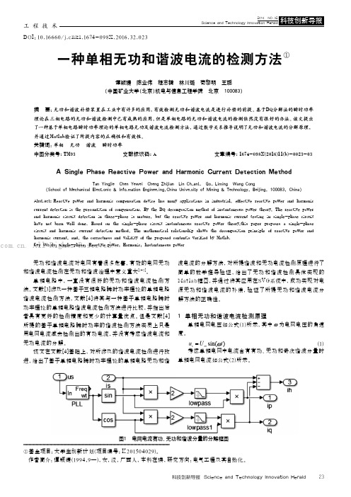
该文在文献[4]基础上,对所涉及的谐波电流检测进行改进,给出了基于单相电路瞬时功率理论的单相电路无功和谐波电流的分解方法,对所提谐波和无功电流检测原理进行了简单的数学推导验证,给出了无功和谐波检测具体实现的Matlab框图,并通过将其应用在SVG系统中,成功实现对电源无功和谐波电流的补偿,验证了所提无功和谐波电流分解方法的正确性。
谐波电流测试方法
谐波电流测试谐波电流测试(Harmonic Current)
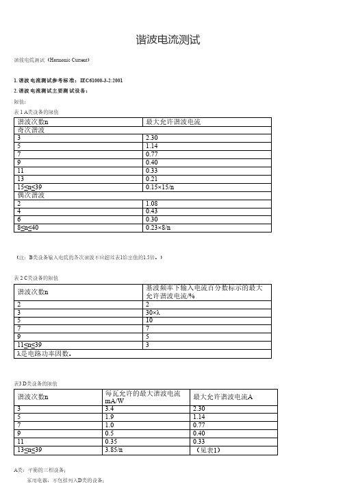
1. 谐波电流测试参考标准:IEC61000-3-2:2001
2. 谐波电流测试主要测试设备:
限值:
表 1 A类设备的限值
谐波次数n最大允许谐波电流奇次谐波
3 2.30
5 1.14
70.77
90.40
110.33
130.21
15≤n≤390.15×15/n
偶次谐波
2 1.08
40.43
60.30
8≤n≤400.23×8/n
(注:B类设备输入电流的各次谐波不应超过表1给出值的1.5倍。
)
表 2 C类设备的限值
谐波次数n 基波频率下输入电流百分数标示的最大允许谐波电流/%
22 330×λ510 77
95
11≤n≤393
λ是电路功率因数。
表3 D类设备的限值
谐波次数n 每瓦允许的最大谐波电流
mA/W最大允许谐波电流A
3 3.
4 2.30
5 1.9 1.14
7 1.00.77
90.50.40 110.350.33
13≤n≤39 3.85/n(见表1)
A类:平衡的三相设备;
家用电器,不包括列入D类的设备;
工具,不包括便携式工具;
白炽灯调光器;
音频设备。
未规定为B、C、D类的设备均视为A类设备。
B类:便携式工具;
不属于专用设备的电弧设备。
C类:照明设备。
D类:功率不大于600W的下列设备:
个人计算机和个人计算机显示器;
电视接收机。
一种单相无功和谐波电流的检测方法
工程技术科技创新导报 Science and Technology Innovation Herald23无功和谐波电流对电网有着很多危害,有效的电网无功和谐波电流检测在无功和谐波治理中意义重大[1-2]。
单相电路中,一直没有很好的无功和谐波电流检测方法。
文献[3]涉及一种基于三相电路瞬时功率理论的单相电路谐波电流检测方法,文献[4]将其与一种基于单相电路瞬时功率理论的单相电路谐波电流检测方法进行比较,并指出后者具有更好的检测精度和更少的计算量优点。
但是文献[4]所提的基于单相电路瞬时功率的谐波检测方法实质上只是用电网电流减去检测出的有功电流,并没有考虑谐波电流和无功电流的分解。
该文在文献[4]基础上,对所涉及的谐波电流检测进行改进,给出了基于单相电路瞬时功率理论的单相电路无功和谐波电流的分解方法,对所提谐波和无功电流检测原理进行了简单的数学推导验证,给出了无功和谐波检测具体实现的Mat lab框图,并通过将其应用在SVG系统中,成功实现对电源无功和谐波电流的补偿,验证了所提无功和谐波电流分解方法的正确性。
1 单相无功和谐波电流检测原理单相电网电压如公式(1)所示,其中为电网电压的角速度。
sin()s m u U t(1)考虑单相电网中电流含有有功、无功和奇次谐波分量时单相电网电流如公式(2)所示。
①基金项目:大学生创新计划(项目编号:K 201504029)。
作者简介:谭颖婕(1994,9—),女,汉,广西人,本科在读,研究方向:电气工程及其自动化。
DOI:10.16660/ k i.1674-098X.2016.32.023一种单相无功和谐波电流的检测方法①谭颖婕 陈业伟 程志键 林川璐 苟黎明 王聪(中国矿业大学(北京)机电与信息工程学院 北京 100083)摘 要:无功和谐波补偿装置在工业中有许多的应用,有效检测无功和谐波电流是进行补偿的前提。
基于DQ分解法的瞬时功率理论在三相电路的无功和谐波检测中已有成熟的应用,但是单相电路的无功和谐波电流的检测依然没有很好的办法。
一种改进无锁相环FBD谐波和无功电流检测方法_史丽萍

2014 年 8 月 25 日
检测原理的局限性分析, 提出一种改进无锁相环检测 方法。 该方法利用基波正序电压提取环节替代锁相环 电路, 对两路线电压进行处理, 得到与基波正序电压 同频同相的三相参考电压信号, 进而求取谐波和无功 补偿指令电流, 避免了锁相环引起的误差。在Matlab/ Simulink环境下搭建仿真模型,对传统FBD法和改进 方法的检测结果进行对比分析。 根据仿真参数搭建实 验平台, 对改进方法进行实验验证。仿真和实验结果 证明了本文所提方法的正确性和可行性。 1 传统FBD法的局限性 传统FBD法检测原理如图1所示。该方法利用锁 相环提取A相电压的相位信息, 经正余弦发生器产生 PLL为锁相 三相参考信号。图1中, ea为系统A相电压; i b、 ic为 环; LPF为低通滤波器; ω为电网实际角频率; ia、 三相负载电流; P∑ 为三相瞬时有功功率; G( 为 (t ) ) p t G( 瞬时有功等效电导, 为直流分量; ia1p、 ) ib1p、 ic1p为基 p t 波正序有功电流; ia 、 ib、 ic为补偿指令电流。
[1,11] [11-12] [10]
[6-8]
, 最终影响谐波和无功补偿指令电流的获取。 鉴于锁相环电路带来的弊端, 通过对传统FBD法
第 51 卷
第 16 期
电测与仪表 Electrical Measurement & Instrumentation
Vol.51 No.16 Aug.25,2014
° ° ° ° ° ° ° ° ° ° ° ° ° ° ° ° ° ° ° ° ° ° ° ° ° ° ° ° ° ° ° ° ° ° ° ° ° ° ° ° ° °
将其经低通滤波器 (LPF )滤波后, 得直流分量 为: G( (φ1-1-Δθ ) =I1cos ) p t
电气化铁路中谐波_无功_负序电流的实时检测方法

p Σ ( t ) =〈 u , i 〉=〈 u , i p 〉=
n =1
∑u i
n np
e. 零功率电流 :
iz = i - i p
即总电流中功率电流 i p 之外的部分 ,根据功率电流 的定义可知 : p Σz ( t ) =〈 u , i z 〉=〈 u , i - i p 〉= 0 所以零功率电流 i z 与 u 正交 , i p 就是 i 在 u 上的投 影。 上面的结果都是在瞬时条件下得到的 , 因而从 理论上讲 ,若有一个合适的功率补偿装置与负载并 联 ,就可以无延时地补偿 i z 。
0 引言
电气化铁路供电系统的负载是电力机车 , 由于 机车的功率大 ,速度 、 负载状况变化频繁 , 因此牵引 电网具有功率因数低 、 谐波含量高 、 负序电流大的特 点 ,不但自身损耗大 ,对公共电网及铁路沿线的设备 也带来了严重的危害 ,必须采取措施治理 。 目前常用的固定容量并联电容器组和 LC 滤波 器等无源设备 ,不能根据负载情况灵活地调节补偿 容量 ,在使用中常出现过补偿和欠补偿 ,无法有效解 决现代化高速 、 重载机车带来的问题 。静止无功发 生器 、 有源滤波器等有源电能质量调节设备体积小 、 重量轻 ,可以根据负载状况灵活调节补偿容量 ,在工 业系统中逐步实用化 。随着电力电子元器件技术的 发展 ,有源电能质量调节设备在电气化铁路系统中 的应用逐渐成为可能 。为了提高有源电能质量调节 器的性能 ,必须研究迅速 、 准确的检测方法 。 目前有源滤波器中常用三相电路瞬时无功功率 理论作为检测方法 。该方法的优点是实时性好 , 主 要缺点是只适用于三相平衡 、 对称电路 ,不能简单地 推广到其他电路 。 FBD 法是时域法中的一种 , 由德国学者 S. Fryze 提出 ,经过 F. Buchholz 和 M. Dpenbrock 等人的进一 步研究 , 逐渐形成体系 , 所以被称为 FBD 法[1 ] 。该 方法实时性好 ,而且不局限于三相电路 ,但目前大多 仅限于理论分析 ,没有得到广泛应用 。 本文提出了两种基于 FBD 法的谐波 、 无功功 率、 负序电流的实时检测方法 。这两种检测方法中 没有 Park 变换过程 , 算法简单 , 不但适用于电气化
谐波如何测试?
谐波如何测试?1.谐波测试两种主要方式有源RF和FEM的第二个关键属性是谐波行为。
谐波行为由非线性器件引起,会导致在比发射频率高数倍的频率下产生输出功率。
由于许多无线标准对带外辐射进行了严格的规定,所以工程师会通过测量谐波来评估RF或FEM是否违反了这些辐射要求。
测量谐波功率的具体方法通常取决于RF的预期用途。
对于通用RF等器件备来说,谐波测量需要使用连续波信号来激励DUT,并测量所生成的不同频率的谐波的功率。
相反,在测试无线手机或基站RF时,谐波测量一般需要调制激励信号。
另外,测量谐波功率通常需要特别注意信号的带宽特性。
1)使用连续波激励测量谐波使用连续波激励测量谐波需要使用信号发生器和信号分析仪。
对于激励信号,需要使用信号发生器生成具有所需输出功率和频率的连续波。
信号发生器生成激励信号后,信号分析仪在数倍于输入频率的频率下测量输出功率。
常见的谐波测量有三次谐波和五次谐波,分别在3倍和5倍的激励频率下进行测量。
RF信号分析仪提供了多种测量方法来测量谐波的输出功率。
一个直截了当的方法是将分析仪调至谐波的预期频率,并进行峰值搜索以找到谐波。
例如,如果要测量生成1GHz信号时的PA三次谐波,则三次谐波的频率就是3GHz。
测量谐波功率的另一种方法是使用信号分析仪的零展频(zero span)模式在时域中进行测量。
配置为零展频模式的信号分析仪可以有效地进行一系列功率带内测量,并将结果以时间的函数形式表现出来。
在此模式下,可以在时域上测量选通窗口中不同频率的功率,并使用信号分析仪内置的取平均功能进行计算。
2)使用调制激励的谐波实际上,许多PA被用来放大调制信号,而且这些PA的谐波性能需要调制激励。
与使用连续波类似,通常在接近设备饱和点的功率电平下,将已知功率激励信号发送到PA的输入端。
测量谐波输出功率时,工程师通常会根据测量时间和所需的准确度等不同限制条件而采用图通方法。
实际上,3GPP LTE和IEEE 802.11ac等无线标准并没有对谐波的要求进行具体的规定,而是规定了在一定频率范围内最大杂散辐射要求。
谐波及无功电流的直接检测方法
谐波及无功电流的直接检测方法孙生鸿,李 鹏,陈志业(华北电力大学电力工程系,河北省保定市071003)摘要:分析了现有的谐波及无功电流检测方法,提出了一种快速的谐波及无功电流直接检测新方法。
该直接检测方法引入比例微分环节(PD )作为负反馈,可以补偿滤波环节的延时,显著提高动态响应速度,并具有较好的检测精度。
当电网电压不对称时该方法同样适用。
最后,通过M A TLAB 仿真,验证了快速直接检测方法的有效性。
关键词:谐波电流;无功电流;检测;负反馈;M A TLAB 中图分类号:TM 93收稿日期:2002204211。
教育部博士点专项科研基金资助项目(1999007904)。
0 引言随着电力电子及非线性负荷的广泛应用,如何抑制电网谐波、提高电能质量问题已经提上日程。
目前现场大多采用无源滤波补偿装置和A PF 等有源滤波补偿装置,而有源滤波器具有能够实现动态连续实时补偿、不受电网元件影响等特点,在抑制电网谐波、提高电能质量方面显示出了强大的生命力。
为了实现有源滤波器件的实时性及良好的补偿性能,谐波及无功电流的实时检测就显得非常重要。
目前提出的各种检测方法可能在某一方面具有优越性,但都不尽完善。
现有的检测方法[1~4]主要有:自适应干扰对消法及基于人工神经网络的自适应检测法,这两种方法动态性能不够理想,适合负荷变化缓慢的情况;基于小波分析的检测法,在实时性方面有了改善,但在兼顾动态性和补偿效果两方面还有待进一步研究;基于瞬时无功功率理论的A B 0变换方法和d q 0变换方法,物理意义清晰、易于实现,但A B 0变换方法受电压畸变的影响较大,d q 0变换方法需要三角函数发生器,使实现变得复杂。
为改进以上方法的不足,本文在瞬时无功功率理论的基础上,对现有的谐波及无功电流检测方法进行简化,使检测过程更简洁、方便,力求兼顾并保证谐波及无功电流检测的动态效果和检测精度。
1 检测原理1.1 算法公共电网电压的畸变率往往很低,因此研究中假定电网电压为三相对称正弦电压。
电力系统及其自动化外文翻译--实时检测谐波和单相电路无功功率的方法

Real-Time Method for Detecting Harmonic andReactive Currents of Single-Phase CircuitsAbstractAccording to the characteristics of single-phase circuits and demand of using active filter for real-time detecting harmonic and reactive currents, a detecting method based on Fryze's power definition is proposed. The results of theoretic alanalysis and simulation show that the proposed method is effective in real-time detecting of instantaneous harmonic and reactive currents in single-phase circuits. When only detecting the total reactive currents,this method does not need a phase-locked loop circuit, and it also can be used in some special applications to provide different compensations on the ground of different requirements of electric network. Compared with the other methods based on the theory of instantaneous reactive power, this method is simple and easy to realize.Keywords Active filter; Harmonic; Reactive current; Real-time detection; Single-phase circuit; Electric-network0、IntroductionAt present it is a major tendency to limit harmonics with active filters[]31-,which can not only limit harmonics dynamically and compensate reactive power but also can achieve a continuous and dynamic tracking of the compensation for time-varying harmonic and reactive currents and are not apt to be affected by the resistance of electric network. The key technology of active filter is the real-time detecting of harmonics and reactive currents from load currents to receive reference to meet the need of the active filter.Therefore,the result of the filter will be influenced by the accuracy and real-time ability of the detection.On the basis of the theory of instantaneous reactive power in three-phase circuit,many relatively mature detecting algorithms for harmonics and reactive currents of three-phase circuits have been proposed,such as the methods of p, q, ip and []41-iq However, in single-phase circuits,these methods can not be directly used and an extratwo -phase voltage and current need to be constructed ,which lowers the real -time ability and makes the algorithm more complicated.Refs. [1 ,5] presented a method that is construeted on the basis of Fryze's power definition, but it needs one integral cycle before educing the detection results. Since 1980s , many researchers, e.g .Czarnecki []6, have analyzed the non -sinusoidal currents with new methods, but one integral cycle is alsoneeded and the real -time ability is still poor.In this paper, an in -depth research is made on Fryze's power definition ,which is applied to detect harmonic and reactive currents in single -phase circuits successfully ,and a real -time detecting method for harmonic and reactive currents in single -phase circuits is brought forward. Analysis and simulation reveal that the proposed method can realize real -time detection of the instantaneous harmonic and reactive currents in single -phase circuits. This method does not need a phase -locked loop circuit when only detecting the total reactive currents ,and can provide different compensations on the ground of different requirements of electric network. Compared with other methods with the theory of instantaneous reactive power, this method is simple and easy to realize. The method of detecting reactive power and harmonic currents presented in the Ref.[7] is a special case of application of our method.1、 FundamentalsAccording to Fryze's power definition []5,instaneous active currents is a component of the total currents and its waveform is the same as that of voltage Moreover, the average power absorbed by active currents in one cycle is equal to that by total currents ,and substraction of the instantaneous active currents from the total currents yields the instantaneous reactive currents.Thus ,we have the following expression:()(),t Gu t i s p = (1) ()()()()t p T s T t s T s T d t i t u d t i t u p ⎰⎰==0101(2)()()(),t i t i t i p s q -= (3) where ()t i p and ()t i q are instantaneous active and reactive currents ,respectively;()t u s and ()t i s are instantaneous voltage and instantaneous current of electricnetwork, respectively;G is real constant ratio ,and P is average active power (if U is the effective value of voltage ,then 2/U P G =);T is cycle and t is time.As indicated by Eqs.(1),(2)and( 3),G can be calculated if the average active power and the square of voltage virtual value are available.Then from Eqs.(I)and (3),the instantaneous active current and instantaneous reactive current can be calculated.In general ,assume the detected voltage and current respectively are()t u s =()n n nnwt U φ+∑cos 2 (4)()t i s =()n n nnwt I ϕ+∑cos 2 (5)where n U and n I are the virtual values of the nth harmonic voltage and current,respectively; w is angle frequency; n φ ,and n ϕ are the phases of the nth harmonic voltage and current, respectively; and n=1, 2, •••Then=)(2t u s ()()()()m n n mn m m n n m n m wt m n U U U nwt nwt U U φφφφ++++=+⨯+∑∑cos cos cos 2,2, +()()m n n mn m wt m n U U φφ-+-∑≠cos , (6)where ,,22∑=nn U U (7)and ∑m n ,denotes the sum of the integers whose subscripts n and m are from 1 to ∝In Eq. (6) ,except that 2U isDC component, the other items are all AC components. So the lowpass filter (LPF) whose cut -off frequency is lower than the lowest frequency of alternating signals must be used to filter )(2t u s ,and then 2U is obtained. Similarly ,the product of instantaneous current and instantaneous voltage ,P ,isp=()t u s ()t i s =()()m n n m n m nwt nwt U I ϕφ++∑cos cos 2,=()()m n n mn m wt m n U I P ϕφ++++∑cos ,+()()m n n mn m wt m n U I ϕφ-+-∑≠cos (8) whereP=∑∞=1cos n n n n I U ψ (9)and n ψ=m n ϕφ-is called the power factor angle of the nth harmonic.Similarly ,in Eq.(8 )all the items are AC components except for P. Thus the low -pass filter whose cut -off frequency is lower than the lowest frequency of alternating signals must be used to filter p ,and then P is obtained.After working out P and 2U ,the functional block diagram is constructed as shown in Fig. 1,where the real -time detection of harmonics and instantaneous reactive currents are performed on the basis of Fryze's power definition in single -phase circuit. Although there is a division unit, it is not difficult to realize.Fig.1 Real -time detection of harmonic and reactive current2、 Some Special Applications of the Detecting MethodIn Fig .l , the outputs ()t i p and ()t i q vary with the input ()t u s ,so this circuit can provide different reference compensations on the ground of different requirements of electric network. Three cases of application are analyzed as follows.2.1 Real -time detection of total reactive currents If the compensation is only for the reactive power, then the reactive currents needto be detected.Assume ()t i s and ()t u s are the current and voltage of the detected objects ;then from Eqs. (1),(2),(4) and(9),the outputs ()t i p and ()t i q in Fig.1 are obtained(the derivation process is omitted here):()t i p =()n n n nnwt I φψ+∑cos cos 2 (10)()t i q =()n n n nnwt I φψ+∑cos sin 2 (11)Obviously ,()t i p is the sum of the harmonic active currents, called the totalactive currents.()t i q is the sum of the harmonic reactive currents and the fundamentalactive currents, called the total reactive currents.Therefore, ()t i q ,the output in Fig. 1,is used as a reference to compensate the reactive power.When only detecting the total reactive currents ,there is no need to detect the unit sinusoidal signal with the same phase as the detected voltage ,and hence no need to use the phase -locked loop circuit too. This is one of the merits of this method.2.2 Real -time detection of harmonic and fundamental reactive currentsIf ()t u s =()1cos 2φ+wt , then,n U =⎭⎬⎫⎩⎨⎧=≠,1,1,1,n n o (12) Substituting Eq. (12) into Eq.(9),we obtainP=11cos ψI (13) Then by Eq. (1) ,()t i p is expressed as()t i p =()111cos cos 2φψ+wt I (14) Obviously,()t i p is the fundamental active part of the detected current, and then()t i q is the sum of harmonic and fundamental reactive currents. Therefore ,the output ()t i q is used as a reference value to limit harmonics and compensate reactivecurrents.Since 2U =1,Fig.2 is obtained by simplification of Fig.1. In Fig.2,()t u s is an unit sinusoidal signal which has the same phase as the detected voltage and can be obtained from the phase -locked loop circuit.Fig.2 Real -time detection of harmonic and fundamental reactive current2.3 Real -time detection of harmonic currentsWhen only harmonics need to be limited, harmonic currents should be detected. We first detect the fundamental currents ,and then subtract the fundamental currents from the total currents ,to obtain the harmonic currents.If()t u s =()11sin 2φ+wt Iby Eq. (8) we obtainP=11sin ψI (15) ()t i p =()11sin sin 2φψ+wt (16) where ()t i p has the same value as the fundamental reactive current. 2.1,the circuit ofdetecting harmonic currents can be constructed, as shown in Fig.3 .Fig.3 Real -time detection of harmonic currentsIn Fig.3, ()t i h is harmonic current. Fig.3 is the same as the detecting blockdiagram of Ref.[7],so the method for detecting harmonics in single-phase circuits can be regarded as a special case of the proposed detecting method based on the Fryze's power definition.3、Simulation AnalysisThe above three kinds of detecting circuits are simulated on Matlab/Simulink. The results of simulation are summarized as follows.The simulation result of Fig.1 is in Fig.4 .The spectra and waveforms of the voltage and current are in Fig.4( a)-(d).The real waveform of the total reactive currents(solid line)and the waveform from the detected circuit (broken line) are in Fig.4 (e),and the real waveform (solid line) of the total active currents and the waveform from the detected circuit (broken line) are in Fig.4(f). The actual values of the total active and reactive currents can be calculated from Eqs.(10) and(11).It is seen that the detected values of the total active and reactive currents are the same as the actual values,showing that this method is effective. The waveform of the total active currents is the same as that of the power grid voltage. It is the merit of this method.The simulation result of Fig.2 is in Fig.5 .The current which is added to the detected circuit is the same as that in Fig.4 (c) .The voltage which is added to the detected circuit is the unit sinusoidal signal which not only has the same phase as the voltage signal in Fig.4 (a) but also is 2times the value of the voltage. The actual and detected waveforms of the fundamental active current are shown in Fig.5 (a) where the actual waveform of the fundamental active current is calculated from the Eq.(14).The actual waveform of the harmonic and fundamental reactive current (solid line) and the detected waveform (brocken line) are shown in Fig.5(b),where the actual waveform is the difference between the detected current and the fundamental active component in it. It is seen that the detected results agree with the actual ones for both active currents and harmonic and fundamental reactive currents.The simulation result of Fig.3 is in Fig.6 .Assume that the detected current is a square wave current which lags voltage by 1/10 cycle,and that the voltage input to the circuit to be tested,which has the same phase as the detected voltage and leads it by 900,is 2times the unit wave From Fig.6, it is seen that the spectrum of the detectedharmonic current is the same as that of the detected current except the fundamental current; that is,the distribution and magnitude of the detected harmonic is the same as that of the harmonic in the detected current.Fig .7 shows the simulated performance of the dynamic response of the proposed method. Assume that the electric-network current is 1800square wave,which lags voltage by 360. For ease of observation,suppose the amplitude of the current increases from 100 A to 200 A between 20-30 ms,and the waveform of current is shown in Fig.7 (a).Fig.7 (b)-(d) are respectively the outputs of the low-pass filter, the detected results of the fundamental current and the harmonic current. It is found that both the outputs of the low-pass filter and the detected results of the fundamental and harmonic currents begin to change at about 30 ms, and then stabilize at 40 ms. Therefore,the time lag is 10 ms. The time lag is caused by the filter. In fact, the lowest order of harmonics to be filtered is 2. Using the digital filtering method to get the average value in one cycle of the lowest harmonic,the steady and accurate result can be obtained after a half power cycle,i.e. ,10m s.It is obvious that the performance of the dynamic response of this method is good.(a) The voltage of electric network (b) The spectrum of voltage(c) The current of electric network (d) The spectrum of current(e) The total reactive current (f) The total active currentFig.4 The detected total active and reactive current(a) The active current component (b) Harmonic and fundamental reactive currentFig.5 The detected active current and harmonic and fundamental reactive current(a) The current of electric network (b) The spectrum of current(c) The detected harmonic current (d) The spectrum of harmonic currentFig.6 Dynamically detected harmonic current(a) The current of electric network (b) The output current of LPF(c)The fundamental current (d)The harmonic currentFig.7 The simulation of performance of dynamic response4 、ConclusionIn this paper, a real-time detecting method for harmonics and reactive currents on the basis of the Fryze's power definition is constructed. Analysis and simulation reveal that this method is simple and easy to realize and can detect harmonic currents fundamental reactive(active)currents and total reactive (active) currents dynamically and accurately. When only detecting the total reactive currents,this method does not need a phase-locked loop circuit.References[1] Wang Z A, Yang J, Liu J J. Harmonic limitation and reactive powercompensation[M], Beijing; Machine Press ,1998(in Chinese).[2 ] Lin B R ,Yang B R .Current harmonics elimination with a series hybrid activefilter[ A ] .In; IEEE International Symposium on Industrial Electronics (ISIE) [C].Pusan, Kore a, 2001.566-570.[3] Jiang M C. Aanlysis and design of a novel three-phase active power filter[J] .IEEE Transactions on Aerospace and Electronic Systems, 37(3) ,2001: 824831.[4] Ren Y F, Li H S,He G, et al. Two kinds of real-time detecting method forharmonic and reactive current in signal Circuit [J]. Automation of Electrical Power Society, 2003,15(1):95-98(in Chinese).[5] Fryze S. Active, reactive and apparent power in circuits with nonsinusoidalvoltage and current [J]. Elektortech, 1931( 7 ):193-203;1931(8):225-234;1932(22):673-676 .[6] Czarnecki L S. Scattered and reactive current, voltage and power in circuits withnonsinusoidal waveforms and their compensation [J]. IEEE Trans Instrum Meas, 1991, 40 (3); 563-567.[7] Li T B,Sun Y H, Liao Z L. Study of a real-time detecting method for reactivecurrent in single circuit [J]. Electrical Measurement and Instrument, 2003 40(451):8-11 (in Chinese).实时检测谐波和单相电路无功功率的方法摘要根据单相电路的特点和为了实时检测谐波和无功功率而使用有源滤波器,一种检测基于Fryze 功率定义的方法被提出。
- 1、下载文档前请自行甄别文档内容的完整性,平台不提供额外的编辑、内容补充、找答案等附加服务。
- 2、"仅部分预览"的文档,不可在线预览部分如存在完整性等问题,可反馈申请退款(可完整预览的文档不适用该条件!)。
- 3、如文档侵犯您的权益,请联系客服反馈,我们会尽快为您处理(人工客服工作时间:9:00-18:30)。
在得到基波电压 u1 和基本电流 i1 基础上,只要
求得 u1, i1 的相位差φ1−ϕ 1 就可获得电流的基波有功
分量、基波无功分量。通过三角和差变换,产生如
下含φ1−ϕ 1 式子:
U1I1 cos(φ1 − ϕ1) = Udcos Idcos + Udsin Idsin (9)
将式(9)两边乘以基波电压 u1,即 U1 sin(ω′t + φ1) ,
为解决现有无锁相环方法不能检测无功的缺 陷,本文提出了无锁相环有功分离法和无锁相环无 功分离法的单相检测方法,能同时检测出基波有功、 基波无功、谐波。证明了锁相环中的频率和相位偏 移对检测结果没有影响,因此可以省略锁相环,具 有延时小,受频差和电压畸变影响小,可动态跟踪 电源频率的特点。
2 无锁相环检测方法的数学证明
2010 年 1 月 第 25 卷第 1 期
电工技术学报
TRANSACTIONS OF CHINA ELECTROTECHNICAL SOCIETY
Vol.25 No. 1 Jan. 2010
无锁相环单相无功谐波电流实时检测方法
周福林 李群湛 解绍峰 郭 成
(西南交通大学电气工程学院 成都 610031)
关键词:单相检测 锁相环 无功检测 谐波检测 瞬时无功功率 中图分类号:TM922
Real Time Detecting Method for Single-Phase Reactive and Harmonics Currents Detection Without PLL
Zhou Fulin Li Qunzhan Xie Shaofeng Guo Cheng (Southwest Jiaotong University Chengdu 610031 China )
= ip1 + iq1 + ih
(2)
式中,us 为系统电压;is 为被检测电流;ip1、iq1、ih 分别为基波有功、基波无功、谐波;u1、un 分别为 基波电压和 n 次谐波电压; ω′ 为系统频率;φ1、ϕ1 为基波电压、电流的相位角;φn、ϕn 为 n 次谐波电 压、电流的相位角,n 为大于 1 的整数。
+
U
2 dsin
)
u1
(10)
通过基波电流与有功电流相减可得基波无功电
流,总电流与基波电流相减可得谐波电流,即
⎧⎨⎩iihq1==ii1−−i1i p1
(11)
式(10)和式(11)即是无锁相环的有功分离
法数学模型,其原理图如图 1 所示。无锁相环的无
功分离法的证明过程与无锁相环有功分离法相似,
限于篇幅不作证明,这里仅给出无功分离法检测框
再除 U12
,即
U
2 dcos
+ Ud2sin
,可得基波有功电流
ip1
180
电工技术学报
2010 年 1 月
ip1 = I1 cos(φ1 − ϕ1)sin(ω′t + φ1)
=
U1I1
cos(φ1 U12
−
ϕ1
)
U1
sin(ω′t
+
φ1)
=
(Udcos Idcos
U
2 dcos
+ Udsin Idsin
鉴于锁相环所带来的一系列弊端,开始了关于
第 25 卷第 1 期
周福林等 无锁相环单相无功谐波电流实时检测方法
179
取消锁相环的一系列研究。在三相系统中,无锁相 环方法只适合于三相系统中的基波和谐波检测,不 能 分 离 基 波 中 的 有 功 、 无 功 [8-11] ; 在 单 相 系 统 中 , 基于 d-q,ip-iq 的单相检测方法中,无锁相环方法同 样只能检测基波和谐波,无法分离出基波的有功、 无功[7]。文献[12]提出了一种基于电源频率等于参考 信号频率条件下的一种无锁相环检测方法,但未探 讨频率偏差的影响,不能跟踪电源频率变化,并且, 由功率角得有功电流过程中,只能对基波检测电流 延时得到有功电流,实时性不够理想。文献[13]采 用搜索算法,实时性不够,且在电源电压畸变情况 下,无法检测。文献[14]将负载分解成两种不同频 率,对直流分量提取采用低通滤波器,降低了检测 精度。总之,目前还没有一种完备的无锁相环单相 检测方法。
n=2
+φn
−θ]−
cos[(nω′+ω)t + φn + θ ]}
(3)
将 式 ( 3 ) 中 的 U1 cos[(ω′ − ω)t + φ1 −θ ] 由 Udcos
表示,并乘以正弦参考信号 sin(ωt +θ ) 得
U dcos
sin(ωt
+
θ
)
=
U1 2
sin(ω′t
+
φ1 )
+
U1 2
sin[(2ω
图如图 2 所示。
图 1 无锁相环有功电流分离法 Fig.1 PLL-less detect method by isolating active current
图 2 无锁相环无功电流分离法 Fig.2 PLL-less detect method by isolating reactive current
收稿日期 2008-06-18 改稿日期 2009-02-02
不断扩展,发展到三相四线制[4]、单相电路[5-7]领域。 在单相电路中,虚拟两相、虚拟三相法[6]、有功电 流分离法[7]是几种常见单相电路检测方法,所有这 些方法中都使用了锁相环以获得与电压同频率、同 相位的正弦参考信号。但锁相环本身受电压波动、 频率偏移、电压畸变等因素影响而易出现失锁、检 测精度差等问题。有源滤波技术往往都是运用在电 能质量恶劣的条件下,因此往往容易引起较大的检 测误差。
摘要 在基于 ip-iq 和 d-q 法的单相、三相电路检测方法中,检测性能受锁相环的输出信号误 差制约。不带锁相环的检测方法难以分离出基波有功、基波无功电流。文中提出预设一个任意频 率、任意相位的正弦参考信号代替锁相环的无锁相环单相检测方法,能同时检测出基波有功、基 波无功和谐波,具有延时小、受频差、电压畸变影响小、可自动跟踪电源频率的特性。文中结论 的正确性在于可靠提取低频信号,讨论了采用低通滤波器和积分法提取低频信号的特性,结果显 示采用后者,具有更好的检测精度和动态性能。理论结果和仿真证实了方法的正确性。
基波电流分量 i1
i1 = Idcos sin(ωt + θ ) + Idsin cos(ωt + θ )
式中
= I1 sin(ω′t + ϕ1) Idcos = I1 cos[(ω′ − ω)t + ϕ1 −θ ] , Idsin = I1 sin[(ω' − ω)t + ϕ1 −θ ] 。
(8)
−
ω
′)t
+
φ1
+
2θ
]
(4)
同理,将系统电压乘以余弦参考信号得
us
cos(ωt
+
θ
)
=
U1 2
sin[(ω
′
−
ω
)t
+
φ1
−
θ
]
+
U1 2
sin[(ω
′+ω
)t
+
φ1
+
θ
]
+
∑ Un
2
∞
{sin[(nω′ − ω)t
n=2
+ φn
−θ]+
sin[(nω′+ω)t + φn +θ ]}
(5)
将式(5)中的 U1 sin[(ω′ − ω)t + φ1 −θ ] 写成 Udsin, 并乘以余弦参考信号 cos(ωt +θ ) 得
Abstract The effectiveness of single phase and three phase detection method based on ip-iq and d-q transformer is limited by phase lock loop’s(PLL)signal error. The detecting method without PLL is difficult to detect active and reactive current of fundament frequency current. A PLL-less single phase detect method is presented to detect active, reactive and harmonics currents with little time delay. A pre-designed refereed sine signal with random frequency and phase is adopted to replace the PLL. This kind of detecting method has strong immunity to voltage distortion and frequency error, and can vary with voltage frequency automatically in case low frequency signal is detected effectively. The research on low frequency signal’s extracting method of low pass filter(LPF) and integrator shows that the later has better precision and dynamic performance. At last, theory analysis and result of simulation prove the validity of the method.