冯卡门流体力学2
流体力学科普卡门涡街简介

流体力学科普卡门涡街简介在流过圆柱的水流上游释放染色剂,就可以看到水流绕过圆柱后形成的卡门涡街,条件是流动的雷诺数要大概在40~150的范围内。
导读冯·卡门在普朗特的指导下,于1908年获得博士学位后,留在哥廷根大学当助教。
1911年的时候,普朗特让博士生哈依门兹在水槽流动中观察圆柱后面的流动分离。
但哈依门兹在进行实验时,发现圆柱后的尾迹总是在不断地摆动。
一开始普朗特怀疑是圆柱体不够圆或者水槽不对称导致的,可是,无论哈依门兹怎么改进实验装置,水流还是在继续摆动。
冯·卡门当时每天去关心哈依门兹的工作,他想,如果水流始终在摆动,可能这就是一个必然的现象。
利用周末的时间,冯·卡门试着计算了一下涡系的稳定性。
得到的结论是:从圆柱脱落的涡如果是对称排列,那就是不稳定的,一定会发展为某种反对称排列的模式。
星期一上班时,冯·卡门向普朗特报告了这一计算结果,普朗特鼓励他把发现写成文章发表出来。
后来人们就把这种现象冠上了卡门的姓氏,称为卡门涡街。
冯·卡门本人并没有宣称这些涡旋是他发现的,因为确实人们很早就在自然界中观察到了这种现象,比如达·芬奇的画中就有一些。
但冯·卡门第一次从理论上证明了:只有当旋涡是反对称排列,且满足某一分布规律时,流动才是稳定的。
01卡门涡街现象在某些条件下,本来均匀而稳定的流动绕过物体时,会在物体的两侧周期性地脱落转向相反的旋涡,这些旋涡在物体的后部形成有规则的交错排列状态。
第一个系统地解释这个现象的人是著名的空气动力学家冯·卡门(Von Karman),并且因为旋涡有规则地交错排列在尾迹两侧,就像街道两边的路灯一样,所以取名为卡门涡街。
各种形状物体的下游都有可能出现卡门涡街,因为圆柱形状最简单,所以多数研究都是基于圆柱后面的流动来进行的。
物体后部是否会出现卡门涡街主要取决于流动的雷诺数,只有当雷诺数处于特定范围时,才会出现规则的卡门涡街。
20世纪的流体力学大师--冯·卡门
历代有许多咏秋千的著名诗句.如杜甫的“万里秋千习 俗同”,刘禹锡的“秋千争次第,牵掩彩绳斜.”南唐冯延已的
“柳外秋千出画墙”,宋代欧阳修的“绿杨楼外出秋千”等
中国的秋千一般为妇女玩耍,特别是·些少数民族还有 固定的玩秋千的节日,汉族多在寒食节,朝鲜族在每年的端 阳节.
本文于2002—10—20收到
这里山戎是占代中国东北的少数民族,说明秋千是从少 数民族传进来的,墙(音6ao),行动敏捷的意思.秋千有许 多名称,古时还称为施钩和骨索,据说在汉代人称千秋.现 在有的地方称打秋千为打悠游,
大约从唐代以后,在文献和文学著作中有大量关于秋千 的记载.唐朝的《天宝遗事》中记载宫中每年寒食节,嫔妃 们竞赛荡秋千的情景,唐玄宗称为“半仙之戏”.
1938年,冯·卡门当选美国科学院院士.二次世界大战 期间,为了航空实验的需要,他设计了世界上首座试验段口 径609.6 cm的风洞,为美国空军的需要进行了一系列研究 1944年,作为现NASA的喷气推进实验室的共同创始人之
一,他成功主持了美国首枚远程导弹和率闻探索研究.德国 战败后, 1945年春,冯-幸门带领个科学家小组到欧洲 对德国科学家和工程师在战争期间取得飞速发展的航空【业
本文读者也读过(10条) 1. 严宗毅.苏卫东 在流体力学教学中调动学生学习主动性,培养创新精神1)[期刊论文]-力学与实践2001,23(3) 2. 周光垐 从考古看史前流体力学的发生和发展[期刊论文]-力学与实践2001,23(5) 3. 冉政 20世纪上半叶中国学者流体力学研究工作概述[会议论文]-2005 4. 包芸.刘欢 流体力学在海洋科学中的发展史[会议论文]-2005 5. 陈然.戴世强 冯·卡门与哥廷根应用力学学派[会议论文]-2007 6. 陈然 流体力学大家G.I.Taylor的学术思想初探[会议论文]-2009 7. 周光垌 流体力学发展的五个时期[期刊论文]-力学与实践2001,23(3) 8. 郭日修 一代宗师 风范长存--记我国第一代工程力学教授罗忠忱[期刊论文]-力学与实践2004,26(1) 9. 常光福.陈云富.方俊俊.张建文.CHANG Guangfu.CHENG Yunfu.FANG Junjun.ZHANG Jianwen 旋转容器内流体模 型验证实验设计[期刊论文]-力学与实践2007,29(4) 10. 周炳红.刘秋生.胡良.姚永龙.胡文瑞 两层流体热毛细对流空间实验研究[期刊论文]-中国科学E辑2002,32(3)
流体力学计算公式
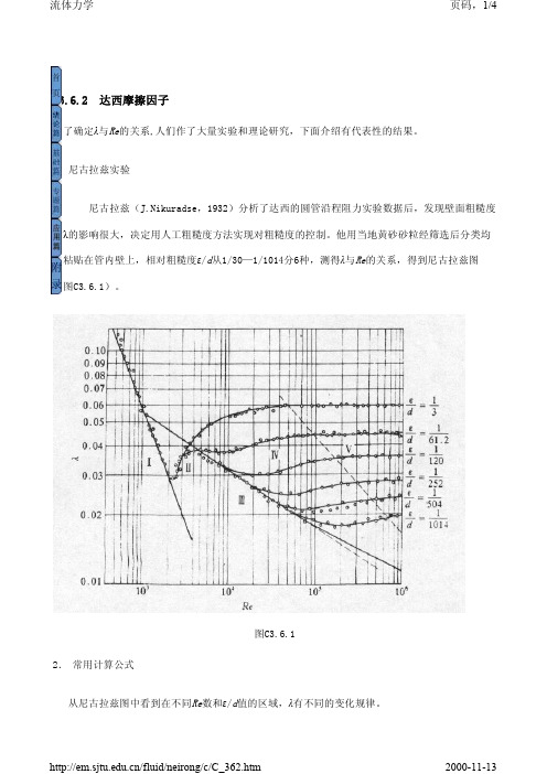
C3.6.2 达西摩擦因子为了确定λ与Re 的关系,人们作了大量实验和理论研究,下面介绍有代表性的结果。
1.尼古拉兹实验尼古拉兹(J.Nikuradse,1932)分析了达西的圆管沿程阻力实验数据后,发现壁面粗糙度对λ的影响很大,决定用人工粗糙度方法实现对粗糙度的控制。
他用当地黄砂砂粒经筛选后分类均匀粘贴在管内壁上,相对粗糙度ε/d 从1/30—1/1014分6种,测得λ与Re 的关系,得到尼古拉兹图(图C3.6.1)。
2. 常用计算公式从尼古拉兹图中看到在不同Re 数和ε/d 值的区域,λ有不同的变化规律。
图C3.6.1(1)层流区由泊肃叶定律推导的沿程水头损失(C3.4.10)式可得代入达西公式(C3.6.3)式,可得层流区λ的解析式上式表明层流区λ与管壁粗糙度无关,写成常用对数形式为上式在双对数坐标系中是一条直线,与尼古拉兹图吻合。
(2)过渡区该区是层流向湍流的转捩区(2000<Re <4000),实验数据分散,无明确规律。
(3)湍流光滑管区当湍流的粘性底层厚度大于壁面粗糙度(δ>ε)时(图C3.6.2)摩擦因子同壁面粗糙度无关,称为湍流光滑管区。
布拉修斯(P.Blasius,1911)运用1/ 7次指数律速度分布式,结合实验数据导出经验公式:上式称为布拉修斯公式,适用范围为4000<Re <105,其优点是显式。
普朗特(L.Prandtl,1933)运用对数律速度分布式(C3.5.18),结合尼古拉兹的实验数据导(C3.6.4)(C3.6.5)(C3.6.6)出上式称为普朗特-史里希廷公式,适用范围为3000<Re < 4×10 6,比布拉修斯公式的适用范围更宽。
(4)湍流完全粗糙管区卡门(Von.Karman,1921)根据湍流脉动相似性假设,结合尼古拉兹的实验数据导出上式称为冯卡门公式, 适用范围为Re > 4160 (d / 2ε) 0.85(5)湍流过渡粗糙管区科尔布鲁克(C.F.Colebrook,1939)将普朗特-史里希廷公式(C3.6.10)式改写为将冯卡门公式(C3.6.11)式改写为然后将上两式合并, 得到△ 上式称为科尔布鲁克公式,适用范围为4000<Re <10 8 。
西奥多·冯·卡门

▲1915-1918年,奥匈帝国军队的服役中止了他在亚琛工业大学设计早 期直升机的生活,最终他与1930年离开亚琛工业大学。移民美国和喷气 动力试验室
1908年的一天,冯·卡门亲眼目睹了法尔芒又一次打破记录的飞行。飞行 结束后,冯·卡门从人群中挤过去,与飞行家之间有过一段精彩的对话。
明了比空气重的东西是绝对飞不起来的,怎么……”。法尔芒幽默 地回答:“是那个研究苹果落地的人吗?幸好我没有读过他的书, 不然,今天就不会得到这次飞行的奖金了。我只是个画家、赛车手, 现在又成了飞行员。至于飞机为什么会飞起来,不关我的事,您作 为教授,应该研究它。祝您成功,再见!”在回家的路上,冯·卡 门坐在疾驶的车里久久地沉思。他对陪他一起来的一位记者说: “看来伟人的话也不一定都对。现在我终于决定我今后的一生该研 究什么了。”冯·卡门拉住记者的手伸出车窗外,立刻有一股风吹 过手面,他说:“我要不惜一切努力去研究风以及在风中飞行的全 部奥秘。总有一天我会向法尔芒讲清楚他的飞机为什么能上天的道 理的。”正是这次参观把冯·卡门引上了毕生从事航空航天气动力 学研究的道路。冯·卡门问法尔芒:“我是研究科学的。有一位伟 大的科学家用他的定律证
中后期生活
▲1944年6月,冯·卡门在纽约市做了肠癌手术。手术引起2处疝 气,使得冯·卡门恢复得缓慢,大约九月中旬返回帕萨迪那。此前 的九月初他还在纽约的时候,他和美国空军司令亨利·阿诺德将军 在拉瓜迪亚机场跑道上会面。阿诺德将军建议他搬到华盛顿特区 领导科学咨询团,并成为军方的长期计划顾问。▲1944年19月23 日,冯·卡门得到这一任命,并在该年12月离开加州理工。▲ 81岁 时,冯·卡门成为首个美国国家科学奖章获得者,在白宫由约翰·肯 尼迪总统颁奖。获奖理由为“他在航空动力学的科学与工程基础 的领导才能”、“在力学各方面的有影响力的教学和相关贡献以 及对于美国军队杰出的帮助”以及“对于国际科学工程合作的促 进”。▲1963年,他去世在去亚琛的路上,并葬在帕萨迪娜。 ▲他终生未婚。 冯·卡门的名望源于他用数学工具来研究流体流动, 并通过解释那些接过来指导实际设计。他在认识到现代喷气飞机 中普遍存在的后掠翼的重要性方面起到重要作用。
冯卡门流体力学
von Karman Institute for Fluid DynamicsChaussée de Waterloo, 72B - 1640 Rhode Saint Genèse - BelgiumPOTENTIAL APPLICATIONS OF INDUCTION HEATING TOAEROSPACE TECHNOLOGIES IN THE 1.2 MW PLASMATRONOF THE VON KARMAN INSTITUTEB. Bottin & M. CarbonaroElectromagnetic Processing of Materials, Paris, France,May 26-29, 1997(Internal VKI number: reprint 1997-20)POTENTIAL APPLICATIONS OF INDUCTION HEATING TO AEROSPACE TECHNOLOGIES IN THE1.2 MW PLASMATRON OF THE VON KARMAN INSTITUTEB ENOÎT BOTTIN (P H.D.C ANDIDATE)M ARIO CARBONARO (H EAD OF A ERONAUTICS/A EROSPACE D EPARTMENT) THE VON KARMAN INSTITUTE FOR FLUID DYNAMICS72 C HAUSSEE DE W ATERLOOB-1640 R HODE-S AINT-G ENESEBELGIUMLes missions spatiales présentes et à venir incluent une phase de rentrée atmosphérique (sur la Terre ou ailleurs) à des vitesses hypersoniques provoquant un important échauffement du nez et des bords d’attaque des véhicules. Les matériaux de protection thermique (TPS) utilisés pour protéger la structure, le chargement et l’équipage doivent être essayés avant le vol. Le Plasmatron construit à l’IVK permettra la génération inductive de plasma à des températures et des pressions correspondant à toutes les conditions de rentrée depuis l’orbite terrestre ou la Lune, et sera capable de couvrir partiellement les entrées dans d’autres atmosphères ou les retours depuis les planètes éloignées comme Mars. Sa puissance électrique de 1200 kW en fait l’installation de ce type la plus puissante au monde. Il peut fonctionner de 4 Pa à 1 atmosphère à des débits de l’ordre de 0.8 m3/s. Sa capacité à fonctionner dans les régimes subsonique et supersonique permet un ajustement des paramètres de la simulation de la rentrée afin de couvrir de nombreux aspects de ce problème.Present and future space missions involve entry phases in an atmosphere (Earth or alien) at hypersonic velocities causing tremendous heating to the nose and leading edge parts of entering vehicles. Special Thermal Protection System (TPS) materials are used to protect the structure, payload and crew during the descent, which have to be tested before flight. The Plasmatron being built at the VKI will allow inductive generation of plasma at temperatures and pressures matching all re-entry conditions from Earth orbit and lunar flights, and be able to partly cope with entries into other atmospheres or re-entries from further bodies, such as Mars. It has an electrical available power of 1200 kW and is the most powerful of its kind in the world at present. It can operate from 4 Pa to 1 atmosphere with flow rates of the order of 0.8 m3/h. Its operating capability in both the subsonic and supersonic regimes allows a fine tuning of the re-entry parameters simulation to cover many different aspects of the problem.Aerothermodynamic constraints of re-entry vehiclesSince the dawn of the space age, mankind has had to face problems associated to the high temperatures encountered by missiles and spacecraft during atmospheric entry. Celestial mechanics impose huge velocities to vehicles designed to reach space. The circular orbital velocity is around 8 km/s, while the Earth escape velocity is about 11 km/s. Velocities required to reach other planets are even higher [1]. When a spacecraft needs to come back on Earth, it approaches our planet at identical velocities and has to slow down to reach the ground at a velocity compatible with soft landing. The spacecraft usually has no thrust available to break its speed and has to rely on aerodynamic breaking. Multiple orbit entries using the atmosphere to slow down little by little are undesirable because of repeated passages through the van Allen belts [2]. The only option is the single-pass trajectory, which can be ballistic or lifting [3].Re-entry flight lies in the hypersonic regime, characterised by the presence of a very strong shock in front of the vehicle. The leading edges and nose regions will be faced by a quasi-normal shock and experience the highest temperatures as through the shock wave, the flow is submitted to a tremendous deceleration to subsonic velocity. The resulting loss of kinetic energy has to be compensated by an increase of thermal energy. Figure 1 illustrates this aspect of re-entry. The flooded contours show temperatures behind the shock wave, as a function of velocity and altitude (exponential atmosphere has been used in this calculation).The figure supposes chemical equilibrium behind the shock wave. The other extreme, a frozen flow across the shock wave, would yield temperatures constant for a given velocity, equal to the temperature computed at low altitude.The bold trajectory entering at 7 km/s corresponds to a design flight path of the now-defunct European vehicle Hermes [4]. Although the temperature of the outside atmosphere 051015202040608010035000300002500020000150001000080006000400020000.120.060.060.120.230.230.350.1750.350.1750.70.70.20.40.001downstream temperature (K)O 2 mass frac.N 2 mass frac.e - mole frac.Velocity (km/s)A l t i t u d e (k m )Normal shock Hermes entry Typical lunar return entryFigure 1 : "aerothermodynamic environment of typical re-entry flight paths"would be below 0°C, the hyper-velocity effect causes the local temperature to rise to more than 5000 K around the nose region. As the vehicle goes down, density increases and so does the shock strength. Because Hermes was designed as a lifting vehicle, it can use its lift to reduce its velocity at relatively high altitudes and keep the temperature below 6000 K. The same is not the case with ballistic capsules who have to rely solely on drag to slow down. These tend to slow at lower altitudes and thus encounter higher temperatures than their lifting counterparts. As an example, the re-entry path starting at 11 km/s is a simplified computation of an Apollo re-entry from the Moon [5], showing a temperature rises from about 8000 K to about 11000 K before the deceleration takes place. High temperatures also have an effect on the chemical composition of the gas surrounding the vehicle. Isolines of 25%, 50% and 100% of O2 and N2 dissociation (in mass fraction), as well as 0.1%, 20% and 40% of electron mole fraction, show that flight paths cross zones of total oxygen and nitrogen dissociation, and re-entries from escape velocity and beyond imply an ionised environment (the manned re-entry from Mars as planned by NASA has initial velocities between 12 and 16 km/s [6]. A look on figure 1 indicates temperatures no less than 10000 K, with a high ionisation ratio).Hence, we can conclude that the aerothermodynamic environment of a re-entry trajectory implies high-temperatures and chemistry. The survival of the spacecraft as it crosses this lethal part of the flight relies on the efficient protection against the high heat flux rates.The problem of accurate Thermal Protection Systems testingThe need for an efficient Thermal Protection System (TPS) material to protect the shuttle during the re-entry phase directly calls for a need to test the candidate TPS samples in a similar environment. As shown by Kolesnikov [7], the accurate simulation of the stagnation-point flow on a re-entry vehicle can be achieved if the total enthalpy, pressure and velocity gradient at the boundary layer edge are properly simulated, provided that the chemical composition is identical. This allows to simulate heat transfers from supersonic flows by subsonic flow experiments, provided these simulation variables match.Long-duration testing of samples in flows with temperatures of several thousands of degrees can be achieved by immersion in plasma flows, generated by electric arc or induction. In the precise case of TPS testing, arc-jets are less suited because the flow is polluted by copper vapours generated by erosion of the electrodes, which then causes changes of sample catalycity when deposited on its surface. In this respect, the ideal tool of investigation logically appears as being the induction-heated generator because of the plasma purity. This was already the solution used by the Russians, who built several « plasmatrons » during the development of their space programmes [8]. Perhaps the most striking difference between these facilities and the classical plasma torches used throughout the world in manufacturing processes and powder metallurgy is their operation at under-atmospheric pressures - a direct consequence of the rather unique application to re-entry problems.The VKI PlasmatronThe Plasmatron Project is a direct heir of the Hermes programme. Its requirements are directly derived from Hermes flight conditions, such as shown on figure 2 for the re-entry trajectory illustrated in figure 1. The heat flux has been computed considering radiative equilibrium with a surface emissivity of 0.85, typical of Si-C materials currently used as TPS. The graph shows nominal variations of heat flux up to 825 kW/m2 and of stagnation pressureup to 140 hPa for the nose region. Considering unsteady load peaks and emergency re-entry trajectories, the relevant total heat flux and pressure range has been defined as (350 - 1200kW/m 2) and (5 - 175 hPa). Figure 3 shows the actual requirements matrix. This set of operating conditions is to be obtained in the subsonic flow regime. The facility is further required to cover at least part of the envelope in the supersonic regime.The Plasmatron faci-lity is sketched in figure 4.Its power source is a 1400kVA high-frequency gene-rator using the solid-state thyristor and MOS inverteroscillator technology, pro-viding 400 kHz high-frequency current to theinductor and torch unit.Gas is supplied either from the VKI compressed airsystem or from individual bottles. The test chamber,of 1400 mm diameter, is maintained to subatmos-pheric pressures by a set of three volumetric vacuum pumps. All equipment exposed to heat are cooled using a de-ionised water, closed-circuit cooling system. A control system monitors the status of the facility,manages the alarms, and can be programmed to keep constant or varying test conditions. In addition, the facility is equipped with an 80-channel data acquisition system and intrusive and non-intrusive instrumentation to perform diagnostics of the plasma flow [9].In order to cover the matrix imposed by ESA, which includes operating the torch at very low powers, it has been decided to use two torch diameters. The facility has therefore a versatile torch architecture. The coil and quartz tube are mounted in a special air-tight enclosure that is fitted on the test section. Two such casings exist, one for an 80-mm diameter torch and the other for a 160-mm diameter torch. Both torches are protected by a cold crucible to allow high plasma powers. However, in order to perform scientific exploration of the induction region, the smaller torch is alsocapable of operating without cold cage. In thiscase, optical access to the torch is provided by replacing the monospire inductor by amultispire.Versatility also exists in terms ofgenerator efficiency. To be sure that lowpowers can be satisfactorily obtained, thegenerator has been specially designed to workboth with a 15-150 kW reduced output and a100-1050 kW maximum output. Impedancematching between the generator and theplasma will be performed automatically by a 0510152025303501530456075901051201351500400800120016002000Time (min)altitude Mach wall heat flux wall pressure M a c h - a l t i t u d e (k m ) - w a l l p r e s s u r e (h P a )w a l l t e m p e r a t u r e (C ) - w a l l h e a t f l u x (k W /m 2)walltemperature Figure 2 : "flow parameters at the nose during a Hermes re-entry"0200400600800100012000255075100125150175P (hPa)q (k W /m ²)Figure 3 : "ESA requirements diagram"tailor-made matching device driven by the control system. Finally, versatility is further improved by the possibility of inserting a Roots pump in the vacuum circuit in order to reach pressures lower than 1 hPa in the test enclosure, in the aim of performing supersonic tests with a low total pressure (low Mach numbers) or with largely under-expanded jets (high Mach numbers).transformer DCHFcontrol H/Xpumpsstackcooling system enclosurespectroscopicinstrumentationoperatorFigure 4 : "plasmatron concept design"TPS testing in the PlasmatronThe operating range of the VKI Plasmatron is defined by an available plasma power of 620 kW 1, a pumping capacity of 4 Pa - 1 atmosphere with flow rates up to 0.55 m 3/h - 0.818m 3/h and a gas supply mass flow rate capacity of up to 4 g/s (argon start-up)and up to 140 g/s (test gas).Total enthalpies for re-entry are of the order of 30 MJ/kg (orbital) to 60 MJ/kg (lunar).These values are perfectly within the range of an induction-heated plasma generator working under sub-atmospheric conditions. With the total pressure and total enthalpy matching flight data, it follows from our earlier discussion that the velocity gradient will directly govern the heat flux obtained on test samples. Two parameters can be used to tailor its value: the velocity itself (first, the gradients in subsonic and supersonic flows are different and second, the gradient in supersonic flow is Mach-dependent since the shock moves closer to the body with increasing velocity) and the geometry of the sample holder. The operating conditions of figure 3 are defined on a cylindrical, 50 mm diameter sample holder.1 Expected value at 175 hPa considering thermal losses in the torch and radiation losses in the test chamberIt is generally accepted that induction-heated plasmas cannot reach temperatures much higher than 10000 K [10]. This would impose a limit on enthalpy (about 80 MJ/kg), and thus on entry velocity (12.6 km/s). While Earth orbit or lunar entries can be studied during the whole range, testing whole Mars return paths seems difficult, although it is possible to increase the heat transfer by decreasing the sample holder radius. Going from a 50 mm holder to a 30 mm holder would already increase the heat flux by 25%. There are thus ways to circumvent the maximum temperature, except for accurate chemical composition problems. Nevertheless, heat fluxes are so huge that entries without ablating materials are not considered [6] and destructive tests pose technical problems for which this facility has not been designed.On the other hand, the possibility of injecting nearly any mixture of gases (the facility has three supply lines) allows the simulation of a whole class of re-entry problems in alien atmospheres. The technical difficulties are of the same type as for Earth entries, with the addition of highly radiating species in some cases. The supersonic testing capability plays a big role in those cases since it improves the quality of the simulation by creating a radiative shock layer behind the shock wave that adds energy to the convective heat transfer, just like in normal flight. This supersonic capability, coupled with the possibility to increase the working pressure to the atmosphere, should allow a significant extension of the operating envelope. Using other types of test gases can also allow parametric investigation of the effect of various gas-phase ablation products on the heat transfer. Finally, it should also be noted that the reserve of electrical power can be used, instead of increasing the temperature, to increase the mass flow, and thus the size of the torch. The 160-mm torch could already be used for testing bigger materials, from complete TPS tiles to gaps between TPS tiles, windows and portholes, etc. If the need arose, installing still a bigger torch would be feasible, not only from the mechanical aspect of modular torch casings, but also on the electrical aspect of available power.Since induction plasma generators produce conditions similar to the re-entry environment without any pollution, they are an ideal benchmark for the validation of computational fluid dynamics models trying to simulate the 3D aerothermodynamic flow fields around spacecrafts. Numerical simulation is an important part of aerospace research because of its potential to simulate conditions out of range of the experimental facilities. Progress in hypersonic technologies cannot be achieved without the combined use of flight tests, wind tunnel simulation and numerical simulation.References[1] Smith, A. Entry Vehicles Considerations: Ballistic, Lifitng, Capture Braking. A GARD/FDP/VKI special course: Capsule Aerothermodynamics, VKI Lecture Series 1995-06.[2] Loh, W.H.T. Re-Entry and Planetary Entry Physics and Technology 1. Springer-Verlag, New York, 1968.[3] Anderson, J.D.Jr. Introduction to Flight.3rd Edition, Mc-Graw Hill, New York, 1989.[4] Vilain, T. et al. Hermes 1.0: Flux en Rentrée pour SG-1-21. H-NT-1-1345-AMD, Rev.1, 1993.[5] Anderson, J.D.Jr. Hypersonics and High-Temperature Gas Dynamics. Mc-Graw Hill, New York, 1989.[6] Tauber, M.E., Palmer, G.E. & Yang, L. Earth Atmospheric Entry Studies for Manned Mars Missions. J. Thermophysics and Heat Transfer, 6(2), pp. 193-199, 1992.[7] Kolesnikov, A.F. Conditions of Simulation of Stagnation-Point Heat Transfer from a Hign-Enthalpy Flow. Fluid Mechanics (UDC 533.6.011.8), Plenum, 1993 (Mekhanika Zhidkosti i Gaza 1(1), pp. 172-180, 1993)[8] Bottin, B. & Carbonaro, M. The Plasmatron Project. VKI reprint 1996-16.[9] Bottin, B. et al. Design of a New Inductively-Coupled Plasma Wind Tunnel for Re-Entry Material Testing at the von Karman Institute. Wind Tunnels and Wind Tunnel Test techniques, Cambridge, 14-16 April 1997. [10] Boulos, M.I. The Inductively Coupled RF Plasma. J. Pure & Appl. Chem., 57(9), pp. 1321-1352, 1985.。
漫话卡门涡街及其应用
漫话卡门涡街及其应用王振东摘要根据冯·卡门的著作,阐述了卡门涡街研究的历史。
讨论了卡门涡街的应用。
关键词冯·卡门卡门涡街涡旋共振流量计卡门涡街是流体力学中重要的现象。
在自然界中常可遇到,在一定条件下的定常来流绕过某些物体时,物体两侧会周期性地脱落出旋转方向相反、排列规则的双列线涡,经过非线性作用后,形成卡门涡街。
如水流过桥墩,风吹过高塔、烟囱、电线等都会形成卡门涡街。
卡门涡街有一些很重要的应用,因此在学习流体力学时,有必要了解其研究历史及有关的应用情况。
卡门涡街的研究历史冯·卡门(Theodore von Kármán 1881~1963)是美藉匈牙利力学家,近代力学的奠基人之一,1881年5月11日生于匈牙利布达佩斯,1963年5月6日卒于德国亚琛。
他出身于奥匈帝国—个教育学教授的家庭,1902年毕业于布达佩斯皇家工学院,1906年去德国哥廷根(Göttingen)大学求学,在普朗特(Ludwig Prandtl 1875~1953)教授的指导下,完成了关于柱体塑性区内屈曲问题的论文,于1908年获得博士学位。
1911年时,他在哥廷根大学当助教。
普朗特教授当时的研究兴趣,主要集中在边界层问题上。
普朗特交给博士生哈依门兹(Karl Hiemenz )的任务,是设计一个水槽,使能观察到圆柱体后面的流动分裂,用实验来核对按边界层理论计算出来的分裂点。
为此,必须先知道在稳定水流中圆柱体周围的压力强度如何分布。
哈依门兹做好了水槽,但出乎意外的是在进行实验时,发现在水槽中的水流不断地发生激烈的摆动。
哈依门兹向普朗特教授报告这一情况后,普朗特告诉他:“显然,你的圆柱体不够圆”。
可是,当哈依门兹将圆柱体作了非常精细的加工后,水流还是在继续摆动。
普朗特又说:“水槽可能不对称”。
哈依门兹于是又开始细心地调整水槽,但仍不能解决问题。
冯·卡门当時所做的课题与哈依门兹的工作并没有关系,而他每天早上进实验室时总要跑过去问:“哈依门兹先生,现在流动稳定了没有?”哈依门兹非常懊丧地回答:“始终在摆动”。
冯卡门大气紊流模型推导
冯卡门大气紊流模型推导介绍大气紊流是指地球大气中的湍流现象。
冯卡门大气紊流模型是描述大气中的湍流现象的模型。
冯卡门方程冯卡门方程是描述大气紊流的微分方程组。
它包括三个方程:连续性方程、Navier-Stokes方程和状态方程。
连续性方程连续性方程描述了质量守恒的原则,可以表示为:∂ρ∂t+∇⋅(ρu)=0其中,ρ是空气密度,u是速度矢量。
Navier-Stokes方程Navier-Stokes方程描述了动量守恒的原则,可以表示为:∂u ∂t +u⋅∇u=−1ρ∇P+ν∇2u+g其中,P是压力,ν是动力粘性系数,g是重力加速度。
状态方程状态方程描述了气体物理性质与状态之间的关系,通常可以表示为:P=ρRT其中,R是气体常数,T是温度。
大气边界层大气边界层是指大气中靠近地表的一层区域,受到地表摩擦力和大气条件的影响。
在大气边界层中,湍流是主要的运动形式。
大气边界层可以分为三个不同的区域:大气表面层、颠簸层和波动层。
大气表面层大气表面层是距离地表几百米的一层区域。
在大气表面层中,湍流强度较大,主要受到地表摩擦力的影响。
这个区域的湍流可以通过冯卡门大气紊流模型来描述。
颠簸层颠簸层是距离地表几百米到几千米的一层区域。
在颠簸层中,湍流强度逐渐减弱,主要受到大气条件的影响。
波动层波动层是距离地表几千米以上的一层区域。
在波动层中,湍流强度较小,主要受到大气条件和地形等因素的影响。
大气紊流模拟方法大气紊流模拟是通过数值模拟方法来研究大气中的湍流现象。
目前常用的大气紊流模拟方法包括直接数值模拟(DNS)、大涡模拟(LES)和雷诺平均Navier-Stokes 方程模拟(RANS)等。
直接数值模拟(DNS)直接数值模拟是一种通过求解Navier-Stokes方程来模拟湍流的方法。
它可以精确地模拟湍流的细节,但需要消耗大量的计算资源。
大涡模拟(LES)大涡模拟是一种通过分解湍流流场为尺度较大的大涡和尺度较小的小涡来模拟湍流的方法。
工程中的数学方法冯卡门
工程中的数学方法冯卡门导言工程是一门应用科学,数学在工程中扮演着重要的角色。
工程中的数学方法有很多种,其中一种就是冯卡门(FEM,Finite Element Method)。
冯卡门是一种解决工程问题的数值分析方法,通过将实际的问题离散化为有限个小元素,再对这些小元素进行计算和处理,最后得到问题的解决方案。
一、冯卡门的基本原理冯卡门的基本原理是将连续问题离散化为有限个小元素,然后对每个小元素进行计算和处理,最后将这些计算结果合并起来得到整个问题的解决方案。
具体来说,冯卡门首先将实际的工程问题划分为若干个有限元素,每个小元素都有一组自由度和状态参数。
然后,通过建立小元素之间的关联关系,将整个问题转化为一个矩阵方程。
最后,通过对矩阵方程进行求解,得到问题的解决方案。
二、冯卡门的步骤冯卡门的求解过程一般可以分为以下几个步骤:1.划分网格:将实际的工程问题划分为若干个有限元素。
通常情况下,这些小元素需要满足一些几何和物理性质方面的要求。
2.建立节点和单元:对于每个小元素,需要建立节点和单元。
节点是指小元素的顶点,而单元是指相邻节点之间的连接关系。
3.建立节点和单元矩阵:对于每个小元素,需要计算其节点和单元矩阵。
节点矩阵是指描述节点数值变化的矩阵,而单元矩阵是指描述单元内部物理性质变化的矩阵。
4.建立全局矩阵:将所有小元素的节点和单元矩阵合并起来,建立全局矩阵。
全局矩阵描述了整个问题的状态参数变化。
5.施加边界条件:根据实际的工程问题,施加相应的边界条件。
边界条件可以是位移、力、温度等物理量。
6.求解矩阵方程:根据施加的边界条件,求解全局矩阵方程。
通常情况下,可以使用数值方法,如高斯消元法或迭代法,来求解矩阵方程。
7.分析结果:根据求解得到的全局矩阵方程,分析结果并得出问题的解决方案。
可以根据需要,对结果进行后处理和分析。
三、冯卡门的应用领域冯卡门广泛应用于各个领域的工程问题,特别是材料力学、结构力学、流体力学等领域。
工程中的数学方法 冯卡门
工程中的数学方法冯卡门(实用版4篇)目录(篇1)1.冯·卡门方程的概述2.冯·卡门方程的应用3.冯·卡门方程的解法4.冯·卡门方程在工程中的重要性正文(篇1)冯·卡门方程是一个模拟平板变形的四阶椭圆型非线性偏微分方程组,由匈牙利数学家冯·卡门(Von Kármán)于 20 世纪 30 年代提出。
这个方程组描述了平板在受力作用下的变形情况,包括了线性和非线性项,因此求解起来比较复杂。
然而,它在工程领域中具有非常重要的应用价值。
冯·卡门方程在工程中的应用主要集中在航空航天、土木工程和机械工程等领域。
例如,在飞机翼的设计中,由于翼型截面的非线性变化,使用冯·卡门方程可以更精确地计算翼型在受力情况下的变形,从而优化翼型设计,提高飞行效率。
此外,在桥梁和建筑物的设计中,冯·卡门方程也可以用来分析结构在受力情况下的变形情况,确保结构的稳定性和安全性。
虽然冯·卡门方程是一个四阶偏微分方程,求解起来较为复杂,但已经有了一些较为成熟的解法。
例如,有限元法、有限差分法和变分法等。
这些方法可以将冯·卡门方程转化为求解线性方程组,从而降低了计算难度。
同时,随着计算机技术的发展,这些方法在实际应用中的效率和准确性也得到了很大的提高。
总之,冯·卡门方程在工程领域中具有非常重要的应用价值。
它为工程师提供了一种精确分析结构受力变形的方法,有助于优化工程设计,提高结构的稳定性和安全性。
目录(篇2)1.引言2.冯·卡门方程的概念与背景3.冯·卡门方程的应用4.结论正文(篇2)1.引言在现代工程技术中,数学方法发挥着越来越重要的作用,它们为各种实际问题提供了理论支持与解决方案。
其中,冯·卡门方程作为工程中常用的数学方法之一,已在诸多领域取得了显著的应用成果。
本文将简要介绍冯·卡门方程的概念与背景,重点探讨其在实际工程中的应用,以期为相关领域的研究和实践提供有益的参考。
资料力学大师冯卡门
冯卡门西奥多·冯·卡门(1881年——1963年),匈牙利犹太人,1936年入美国籍,是20世纪最伟大的美国工程学家,开创了数学和基础科学在航空和航天和其他技术领域的应用,被誉为“航空航天时代的科学奇才”。
他所在的加利福尼亚理工学院实验室后来成为美国国家航空和航天喷气实验室,我国著名科学家钱伟长、钱学森、郭永怀都是他的亲传弟子。
0传奇故事0德国火箭科学家冯·布劳恩曾说:“冯·卡门是航空和航天领域最杰出的一位元老,远见卓识、敏于创造、精于组织……正是他独具的特色。
”鉴于冯·卡门在科学、技术及教育事业等方面的卓著贡献,美国国会授予他第一枚“国家科学勋章”。
1963年2月18日上午,白宫玫瑰园名人聚集,宾客如云,授勋仪式即将举行。
当年迈的冯·卡门走下台阶时,他因患有严重的关节炎而步履不稳,险些摔倒。
年轻的约翰·肯尼迪总统赶紧走上前,一把将他扶住。
老人抬头报以感激的微笑,继而轻轻推开总统伸出的手,淡淡地说:“总统先生,下坡而行者无须搀扶,惟独举足高攀者才求一臂之力。
” 一枚最高荣誉的勋章,一句含义双关的俏皮话,便是他那具有传奇色彩的人生写照:勋章标志着他在科技事业中的伟大功勋,而俏皮话则刻画了他那丰富多彩的个性品质及对科学事业的殷殷关切之心。
20世纪科学技术得到了迅猛发展,然而像冯·卡门那样在航天技术中独领风骚的人物则凤毛麟角,几近绝迹。
因而他被后人誉为“航空航天时代的科学奇才”。
0科学成就的大小往往与科学家本人的个性品质相联系。
卡门的成功一部分得益于他那开朗幽默、独立民主的性情。
作为一名伟人,显贵、阔佬、军政领袖都竭力想与他交朋友,卡门也乐意与他们交往,他是属于上流社会的。
然而,卡门并不是个势利小人,他会毫不迟疑地把一个花匠介绍给达官显贵们,并且一视同仁。
他曾说过,爱因斯坦诚恳而善良的灵魂正是他所毕生追求的。
卡门幽默风趣,爽朗而又健谈。
- 1、下载文档前请自行甄别文档内容的完整性,平台不提供额外的编辑、内容补充、找答案等附加服务。
- 2、"仅部分预览"的文档,不可在线预览部分如存在完整性等问题,可反馈申请退款(可完整预览的文档不适用该条件!)。
- 3、如文档侵犯您的权益,请联系客服反馈,我们会尽快为您处理(人工客服工作时间:9:00-18:30)。
Ir., PhD student Prof., Head of Aeronautics/Aerospace Department ‡ Dipl.-Ing., currently Research Engineer at DLR Braunschweig, Germany
small-disturbance theory can be applied at the walls (i.e. no non-linear effects such as shock waves come near the walls). The following result can then be derived [7], based on the Cauchy expression of an analytical function and on the theorem of residuals: (3) 1 ⌠ q (ζ) dζ O - qB 2 i π ⌡ (ζ - z) C C is a closed contour based on the test section top and bottom walls, inlet and outlet sections, z is the complex coordinate of any point of the test section and ] is a dummy integration variable along the closed contour C (see figure 2). qw (z) =
y, K top wall inlet x, [ outlet bottom wall z=x+iy ] [LK
steel structure allowing a cryogenic operation to 120 K under 4 atmospheres. Figure 3 shows the aerodynamic circuit of the tunnel. It has a test section 100 x 117 mm2 with the top
* #
A very convenient class of streamlining methods have been developed (wall signature techniques), which use only information at the wind tunnel walls and therefore do not need any representation of the model to be tested (in contrast to more classical methods like mirror images). They are based on a logical decomposition of the complex velocity in three parts: (1) q = qB + qm + qw
3
Cauchy Integral Adaptation Method
Figure 1: Wall interference concept (closed test section)
Interferences are of two types: the change in streamline shapes causes a different pressure distribution (lift interference) and the restriction of cross-section due to the model changes the speed across the airfoil (blockage interference). For a closed test section both effects cause an increase in lift, for an open test section the lift is decreased. Correction methods exist for correcting wind tunnel data, based on potential flow models and mirror image techniques [2, 3] or more recently on panel methods (e.g. [4]). These techniques provide only approximate corrections on a global level. It is also possible to correct the flow itself. Slotted or perforated test sections, allowing part of
von Karman Institute for Fluid Dynamics Chaussée de Waterloo, 72 B - 1640 Rhode Saint Genèse - Belgium
FIRST RUNS OF THE ADAPTIVE WIND TUNNEL T'3 AT VKI: CALIBRATION AND APPLICATION OF A FLEXIBLE WALL ADAPTATION TECHNIQUE ON A NACA0012 AIRFOIL
with qB the complex velocity of the oncoming uniform flow, qm the perturbation to this flow caused exclusively by the model and qw the wall-induced perturbation. Complex velocity is defined using the generic relationship: (2) q=u-iv The final aim is to give the walls a shape such that qw = 0 (no influence of the walls on the flow). The present method supposes that qw is an analytic function and that qm can be developed in a Laurent series. The former hypothesis implies that
A flexible-wall wind tunnel has recently been loaned by ONERA to VKI. After calibration, it has been used to show the interest of the mechanical wall adaptation process in which, by altering the test section wall shapes, 2D models can be tested in interference-free conditions similar to free flight. The technique has been used on a NACA 0012 airfoil and shown to be applicable with height-tochord ratios of 1 instead of the classical limit of 3 or 4 in closed tunnels.
2
Introduction
Wind tunnel measurements of airfoil characteristics are biased by wall interferences [1] which manifest themselves in closed and open test sections because of the difference in boundary conditions (see figure 1 for a conceptual example).