音频蓝牙模块说明书V1.00
中星微蓝牙模块中文说明书

℃ ℃
V
6
WS9621NLSC_MODULE
7.封装信息:
8.典型应用电路:
7
WS9621NLSC_MODULE (1)基本应用电路
8
WS9621NLSC_MODULE (2)单功放应用电路
9
WS9621NLSC_MODULE (3)双功放应用电路
9 模块工作流程:
11
10 已知问题列表
(1) (2) (3) (4) 部分手机的播放器由于兼容性的问题,播放音乐时无上一曲下一曲功能. 非正常断电的情况下,Bluetooth Module 不支持自动回连功能. 上电的瞬间音频的输出端有短暂的悬空状态,音箱极有可能会发出一点电流声. 当机内配对列表中存在已配对的设备,自动回连动作可能与手机端配对动作发生 冲突导致偶尔的配对失败现象。
WS9621NLSC_MODULE
Bluetooth Module for WS9621NLSC
Datasheet Version 1.0
版本说明
版本号r V1.0 日期 2012-8-30 创建者 Sun xuefeng 版本说明 初始版本
1
WS9621NLSC_MODULE
2
WS9621NLSC_MODULE
Power Supply Current (With a normal 3.7V battery voltage)
Recommended Operating Conditions
Storage temperature Operating temperature range Supply voltage: VBAT
2. 主要应用:
支持降噪功能的蓝牙立体声耳机 无线立体声音箱
深圳云里物里科技股份有限公司蓝牙模块MS50SFA1说明书

股票代码:872374产品型号MODEL NO/DESCRIPTION产品名称蓝牙从模块产品型号MS50SFA1适用固件版本V2.4.x Version V1.0发布时间2020-05-26目录1. 产品概述 (3)2. 应用领域 (4)3. 模块尺寸图 (4)4. 电气参数 (5)5. 模块管脚图 (6)6. 引脚定义 (6)7. 模块使用操作说明 (8)8. 功耗参数 (17)9. PCB设计说明 (18)10. MCU参考代码 (19)11. 模块原理图 (22)12. 回流焊温度曲线图 (23)13. 支持设备 (23)14. 注意事项 (23)15. 包装信息 (24)16. 认证信息 (25)17. 质量保证 (25)附件:版本说明 (26)1.产品概述MS50SFA1串口从模块采用nRF52810 芯片,通过UART(串口)操作可以实现模块与手机(或其它主设备)之间数据传输。
本模块为从模块,有广播和连接状态,可通过命令设置和查看模块的广播名称,修改广播间隔和连接间隔等参数。
使用该模块用户可以快速把数据以蓝牙方式进行传输。
产品特点产品效果图MS50SFA(V1.x)PCB天线产品反面★ 远距离:10-60米(空旷环境);★ BLE协议栈深度优化,睡眠功耗1uA以下;★ 传输速率最快可达11kB/s;★ 支持供电电压检测;★ 支持串口指令配置;★ 支持 Android 4.3+,iOS7.0+;★ 无需 MFi;★ 通过BQB认证(证书编号QDID:138541);★ 带屏蔽罩。
(默认单位:mm 默认公差:±0.1)3.模块尺寸图2.应用领域该模块主要用于短距离的数据无线传输领域。
可以方便的和PC机的蓝牙设备相连,也可以与智能手机之间的数据互通。
避免繁琐的线缆连接,能直接替代串口线。
可广泛应用于智能家居、智能穿戴设备、消费电子、智慧医疗、安防设备、汽车设备、运动健身设备、仪器仪表、远程遥控等需要低功耗蓝牙系统的领域。
蓝牙音频模块说明文档V1.3(5V)
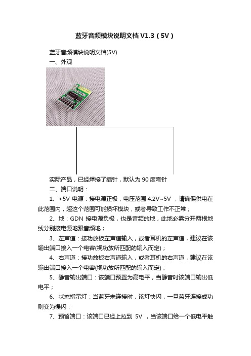
蓝牙音频模块说明文档V1.3(5V)蓝牙音频模块说明文档(5V)一、外观实际产品,已经焊接了插针,默认为90度弯针二、端口说明:1、+5V 电源:接电源正极,电压范围4.2V~5V ,请确保供电在此范围内,超这个范围可能损坏模块,或者导致工作不正常;2、地:GDN 接电源负极,也是音频的地,此地必需分开两根地线分别接电源地跟音频地;3、左声道:接功放板左声道输入,或者耳机的左声道,建议在该输出端口接入一个电容(视功放所匹配的输入而定);4、右声道:接功放板右声道输入,或者耳机的右声道,建议在该输出端口接入一个电容(视功放所匹配的输入而定);5、静音输出端口:该端口预置为高电平,当静音时该端口输出低电平;6、状态指示灯:当蓝牙未连接时,该灯快闪,一旦蓝牙连接成功则变为慢闪;7、预留端口:该端口已经上拉到5V ,当该端口给一个低电平触发后关机,当再次给该端口一个低电平复开机。
系统典型接线图:注意:从蓝牙音频模块到电源或者到音频接口,请采用焊接的方式,不要采用插线的方式,接触电阻比较大会引入噪声。
三、使用注意事项:1、供电电源:蓝牙音频模块属于对高频干扰敏感的电路,建议采用线性稳压电源,若采用DC-DC供电时,请加入LC滤波,降低电源谐波干扰,尤其采用手机充电器等开关电源,电源纹波可能致使蓝牙不能正常连接,而且这类的5V输出,往往在5.1V~5.4V之间,超过了蓝牙音频模块的工作电压;当采用手机适配器等开关电源工作时,请加这个供电电路,电感可不加。
2、接地:由于音频信号对于接地点引起的干扰比较敏感,可以在蓝牙模块的输出插针上面焊两根地结,一根接到电源的负极(GND),另外一根接到功放板的音频输入地,尽量焊在线路板上,不要采用引线接连(容易受干扰),并且建议可以多试一下那个接地点干扰最小;3、天线干扰:蓝牙天线极其容易受到高频,或者强电磁信号干扰,相对来说尽量远离功放板的强信号的地方,并且天线不能紧挨着金属物品,保持一定的距离;4、外壳屏蔽:由于金属外壳的机壳对于蓝牙信号有屏蔽作用,可能衰减蓝牙信号致使接收不良,请保持在有相应的开孔,或者外露。
蓝蜙蜆BGM113蓝牙模块无线电路板参考手册说明书

BRD4301A Reference ManualManualThe Blue Gecko family of the Silicon Labs' Bluetooth modules delivers a high-perform-ance, low energy and easy-to-use Bluetooth solution integrated into a small form factorpackage. Blue Gecko Bluetooth modules combine an integrated antenna, a high per-formance Bluetooth transceiver, an energy efficient 32-bit MCU and a ready to useBluetooth software and SDK.The ultra-low power operating modes and fast wake-up times of the Silicon Labs' ener-gy friendly 32-bit MCUs, combined with the low transmit and receive power consump-tion of the Bluetooth radio, result in a solution optimized for battery powered applica-tions.The Silicon Labs fully certified Bluetooth modules and software are designed to help de-velopers accelerate time to market and reduce development costs and compliance risksby providing a versatile, plug-and-play Bluetooth solution.Development and evaluation of the BGM113 Bluetooth module is possible by attachingthe BRD4301A board to the Wireless Starter Kit (WSTK) Mainboard. This gives accessto the WSTK display, buttons and additional features offered by using the available Ex-pansion Boards.Rev. 1.00BRD4301A Radio Board Description 1. BRD4301A Radio Board DescriptionThe BRD4301A Radio Board contains the BGM113 Blue Gecko Bluetooth Module soldered onto a carrier board with two connectors. The connectors on the carrier board are used for attaching the BRD4301A on to a Silicon Labs Wireless Starter Kit Main-board BRD4001A and together these two boards and the software in the BGM113 Module make up the Blue Gecko Bluetooth Module Wire-less Starter Kit.The BGM113 Bluetooth module and the software are designed to help developers accelerate time to market with end-product design projects. This versatile plug-and-play Bluetooth solution also reduces development costs and minimizes compliance risks. The BGM113 Module is ideal for applications requiring Bluetooth connectivity such as used in connected home, health and fitness, wearables and point-of-sale terminal applications. The BGM113 includes an energy friendly ARM Cortex M4 MCU.A major benefit offered by the BGM113 is that no RF or Bluetooth protocol expertise is required. The BGM113 can be used as a periph-eral along with an external host MCU or applications may be embedded into the built-in MCU using the Bluegiga BGScript™ scripting language. Complete standalone solutions may thus be created with minimal need for external components.1.1 BGM113 Module Block DiagramThe BGM113 Module block diagram is illustrated in the figure below.Lowest power mode with peripheral operational:EM0—ActiveEM2—Deep SleepEM1—Sleep EM4—Hibernate EM4—ShutoffEM3—StopFigure 1.1 Block Diagram| Smart. Connected. Energy-friendly.Rev. 1.00 | 12. System SummaryIntegrated Bluetooth radio and energy friendly MCU•Bluetooth 4.1 compliant and upgradeable to Bluetooth 4.2.•TX power up to +3 dBm•RX sensitivity down to -93 dBm•Integrated high-efficiency chip antenna•38.4 MHz Cortex M4 with DSP instructions and floating-point unit for efficient signal processing•256 kB Flash memory•32 kB RAMLow Energy Consumption•8.8 mA TX current @ 0 dBm•8.7 mA RX current•63 μA/MHz in Energy Mode 0 (EM0)• 1.4 μA EM2 Deep Sleep Current (full RAM retention) and CRYO timer running from ULFRCO• 1.1 μA EM3 Stop current (State/RAM retention, RFSENSE disabled)•Wake on Radio with signal strength detection, preamble pattern detection, frame detection and timeoutWide selection of MCU peripherals•12-bit 1 Msamples/s ADC• 2 x Analog comparator•IDAC (current output DAC)•Up to 14 pins connected to analog channels (APORT) shared between analog comparators, ADC and IDAC •14 General Purpose I/O pins with output state retention and asynchronous interrupts•8-channel DMA controller•12-channel Peripheral Reflex System•Hardware Crypto Acceleration with public key support•Protocol Timer tightly coupled to the radio• 2 x 16-bit Timer/Counter• 3 + 4 Compare/Capture/PWM Channels•32-bit Real Time Counter and Calendar•16-bit Low Energy Timer for waveform generation•16-bit Ultra Low Energy Timer/Counter for periodic wake-up from any Energy Mode•16-bit Pulse Counter with asynchronous operation•Watchdog Timer with dedicated RC Oscillator @ 50 nA• 2 x Universal Synchronous/Asynchronous Receiver/Transmitter (UART/SPI/Smart Card (ISO 7816) / IrDA/I2S)•Low Energy UART (LEUART)•I²C interface with SMBus support and address recognition in EM3 StopIntegrated Bluetooth Smart Software•Bluetooth 4.1 compliant•Central and peripheral roles•Up to 8 simultaneous connections•L2CAP, ATT, GAP, SM and GATT•Any GATT based Bluetooth Smart profile•100 kbps throughputFlexible easy to use APIs•BGAPI™ serial protocol API over UART for modem usage•BGLIB™ host API/library which implementing BGAPI serial protocol•BGScript™ scripting language for standalone usage•Profile Toolkit for creating GATT based servicesFree Software Development Kit (SDK)•BGLIB C source code•BGScript development tools•BGScript and BGLIB example applications•Profile Toolkit examples•DocumentationCertifications•Bluetooth qualified (pending)•CE, FCC, IC, Japan and South-Korea (pending)Wide Operating Range•Supply voltage: 1.85 V to 3.8 V with DC/DC bypass mode •Supply voltage: 2.4 V to 3.8 V with DC/DC enabled •Temperature range: -40°C to +85°C3. BRD4301A Connector3.1 BRD4301A Connector Pin AssociationsThe figure below shows the pin mapping on the connector to the radio pins and their corresponding function on the Wireless Starter Kit Mainboard.GNDF9 / PF3 / VCOM_RTS 3v3NC / P36P200Upper RowNC / P38NC / P40NC / P42NC / P44DBG_SWDIO / PF1 / F0NC / F14BUTTON0 / PD14 / F12LED0 / PD14 / F10VCOM_CTS / PF2 / F8DBG_RESET / F4NC / F2NC / F16VCOM_TX / PA0 / F6PTI_DATA / PB12 / F20NC / F18USB_VBUS5VBoard ID SCLGNDBoard ID SDAUSB_VREG F7 / PA1 / VCOM_RX F5 / tied high / VCOM_ENABLE F3 / NCF1 / PF0 / DBG_SWCLK P45 / NCP43 / NC P41 / NC P39 / NC P37 / tied high / SENSOR_ENABLE F11 / PD15 / LED1F13 / PD15 / BUTTON1F15 / NC F17 / NCF19 / PB13 / PTI_FRAME F21 / NC GNDVMCU_INEXP3 / PF2 / P0P201Lower RowEXP5 / PF3 / P2NC / P4NC / P6GNDVRF_INP35 / NC P7 / PD13 / EXP10P5 / PB13 / EXP8P3 / PB12 / EXP6P1 / PB11 / EXP4P33 / NC P31 / NC P29 / NC P27 / PF1P25 / PF0P23 / PD15P21 / PD14P19 / NC P17 / NC P15 / NC P13 / PC10 / EXP16P11 / PA1 / EXP14P9 / PA0 / EXP12NC / P34NC / P32NC / P30NC / P28NC / P26NC / P24NC / P22NC / P20NC / P18NC / P16NC / P14EXP15 / PC11 / P12NC / P10NC / P8Figure 3.1 Radio Board Connectors3.2 BRD4301A Connector TypeBRD4301A contains two dual-row, female socket, 0.05" pitch polarized connectors (P/N: SFC-120-T2-L-D-A-K-TR) which provide the interface to the Wireless Starter Kit Mainboard. The Mainboard has the corresponding male header pin connectors (P/N: TFC-120-02-F-D-LC-ND).BRD4301A ConnectorMechanical Details 4. Mechanical DetailsModule board is illustrated in the figures below.The BGM113 BluetoothFigure 4.1 BRD4301A Top View Array Figure 4.2 BRD4301A Bottom ViewRev. 1.00 | 5Board Revision History and Errata 5. Board Revision History and Errata5.1 Revision HistoryRadio Board revision is printed on the backside of the BRD4301A Radio Board.Table 5.1. Radio Board Revision History5.2 ErrataRev. A00No known errata for this board revision. | Smart. Connected. Energy-friendly.Rev. 1.00 | 6Document Revision History 6. Document Revision HistoryRevision 1.002015-07-08Initial document revision.Silicon Laboratories Inc.400 West Cesar Chavez Austin, TX 78701USASmart.Connected.Energy-Friendly .Products/productsQuality /qualitySupport and CommunityDisclaimerSilicon Laboratories intends to provide customers with the latest, accurate, and in-depth documentation of all peripherals and modules available for system and software implementers using or intending to use the Silicon Laboratories products. Characterization data, available modules and peripherals, memory sizes and memory addresses refer to each specific device, and "Typical" parameters provided can and do vary in different applications. Application examples described herein are for illustrative purposes only. Silicon Laboratories reserves the right to make changes without further notice and limitation to product information, specifications, and descriptions herein, and does not give warranties as to the accuracy or completeness of the included information. Silicon Laboratories shall have no liability for the consequences of use of the information supplied herein. This document does not imply or express copyright licenses granted hereunder to design or fabricate any integrated circuits. The products are not designed or authorized to be used within any Life Support System without the specific written consent of Silicon Laboratories. A "Life Support System" is any product or system intended to support or sustain life and/or health, which, if it fails, can be reasonably expected to result in significant personal injury or death. Silicon Laboratories products are not designed or authorized for military applications. Silicon Laboratories products shall under no circumstances be used in weapons of mass destruction including (but not limited to) nuclear, biological or chemical weapons, or missiles capable of delivering such weapons.Trademark InformationSilicon Laboratories Inc.® , Silicon Laboratories®, Silicon Labs®, SiLabs® and the Silicon Labs logo®, Bluegiga®, Bluegiga Logo®, Clockbuilder®, CMEMS®, DSPLL®, EFM®, EFM32®, EFR, Ember®, Energy Micro, Energy Micro logo and combinations thereof, "the world’s most energy friendly microcontrollers", Ember®, EZLink®, EZRadio®, EZRadioPRO®, Gecko®, ISOmodem®, Precision32®, ProSLIC®, Simplicity Studio®, SiPHY®, Telegesis, the Telegesis Logo®, USBXpress® and others are trademarks or registered trademarks of Silicon Laborato-ries Inc. ARM, CORTEX, Cortex-M3 and THUMB are trademarks or registered trademarks of ARM Holdings. Keil is a registered trademark of ARM Limited. All other products or brand names mentioned herein are trademarks of their respective holders.。
蓝牙音频模块说明文档V1.3(5V)

蓝牙音频模块说明文档(5V)一、外观实际产品,已经焊接了插针,默认为90度弯针二、端口说明:1、+5V 电源:接电源正极,电压范围4.2V~5V ,请确保供电在此范围内,超这个范围可能损坏模块,或者导致工作不正常;2、地:GDN 接电源负极,也是音频的地,此地必需分开两根地线分别接电源地跟音频地;3、左声道:接功放板左声道输入,或者耳机的左声道,建议在该输出端口接入一个电容(视功放所匹配的输入而定);4、右声道:接功放板右声道输入,或者耳机的右声道,建议在该输出端口接入一个电容(视功放所匹配的输入而定);5、静音输出端口:该端口预置为高电平,当静音时该端口输出低电平;6、状态指示灯:当蓝牙未连接时,该灯快闪,一旦蓝牙连接成功则变为慢闪;7、预留端口:该端口已经上拉到5V ,当该端口给一个低电平触发后关机,当再次给该端口一个低电平复开机。
系统典型接线图:注意:从蓝牙音频模块到电源或者到音频接口,请采用焊接的方式,不要采用插线的方式,接触电阻比较大会引入噪声。
三、使用注意事项:1、供电电源:蓝牙音频模块属于对高频干扰敏感的电路,建议采用线性稳压电源,若采用DC-DC供电时,请加入LC滤波,降低电源谐波干扰,尤其采用手机充电器等开关电源,电源纹波可能致使蓝牙不能正常连接,而且这类的5V输出,往往在5.1V~5.4V之间,超过了蓝牙音频模块的工作电压;当采用手机适配器等开关电源工作时,请加这个供电电路,电感可不加。
2、接地:由于音频信号对于接地点引起的干扰比较敏感,可以在蓝牙模块的输出插针上面焊两根地结,一根接到电源的负极(GND),另外一根接到功放板的音频输入地,尽量焊在线路板上,不要采用引线接连(容易受干扰),并且建议可以多试一下那个接地点干扰最小;3、天线干扰:蓝牙天线极其容易受到高频,或者强电磁信号干扰,相对来说尽量远离功放板的强信号的地方,并且天线不能紧挨着金属物品,保持一定的距离;4、外壳屏蔽:由于金属外壳的机壳对于蓝牙信号有屏蔽作用,可能衰减蓝牙信号致使接收不良,请保持在有相应的开孔,或者外露。
蓝牙模块使用说明书
蓝牙模块使用说明一、模块简介:1、芯片简介该蓝牙模块采用台湾胜普科技有限公司的BMX-02X模块为核心,它采用CSR BLUEcore4-External芯片并配置8Mbit的软件存储空间,成本低,使用方便。
CSR BlueCore4是英国Cambridge Silicon Radio(CSR)公司日前推出的第四代蓝牙硅芯片。
这种硅芯片用于蓝牙技术推广小组(SIG)推出的增强数据传输率(EDR)蓝牙。
CSR的BlueCore4的数据传输率将比现有的v 1.2蓝牙装置快三倍,并且使蓝牙移动电话或手机的耗电量较低。
蓝牙EDR的最大数据传输率为每秒2.1兆比特,而目前v1.2标准传输率则为每秒721千比特。
传输率的提高意味着对一个特定量的数据来说,EDR无线电的工作将比v1.2无线电快三倍,从而减少耗电量,大大有利于依赖蓄电池的移动设备。
CSR BlueCore4完全能与现有蓝牙v1.1和v1.2装置兼容。
蓝牙EDR用一种相移键控(PSK)调制模式取代标准传输率的Gaussian频移键控(GFSK),实现更高的数据传输率。
CSR BlueCore4正在以两种形式提供——一种用于外部“快闪”存储器,一种用于掩模ROM。
BlueCore4-External以一种8×8mm BGA(球形格栅矩阵)封装提供,是十分灵活的解决方案,能够适应迅速更新的市场。
例如,由于BlueCore是目前可以得到的唯一能够支持蓝牙v1.2规格的所有强制和可选功能的硅芯片,BlueCore4-External为PC应用程序提供了理想的解决方案,使它们得益于以三倍速度的传输率无线传输文件,或者同时操作多个高需求的蓝牙链路。
鉴于蓝牙固件安装在芯片只读存储器上,CSR BlueCore4-ROM 的成本较低,占用面积小得多(在小片尺寸包装中为3.8×4mm,在与BC2-ROM和BC3-ROM引脚兼容的BGA中为6×6mm)。
ZX-D33 BLE 主从一体蓝牙模块技术手册说明书
ZX-D33BLE主从一体蓝牙模块技术手册版本:V1.0日期:2022/05/10目录1模块介绍 (2)1.1概述 (2)1.2特性 (3)1.3应用 (3)1.4基础参数表 (4)1.5出厂默认配置参数 (4)2应用接口 (5)2.1模块引脚定义 (5)2.2引脚功能表 (5)2.3特殊引脚IO功能表 (6)2.4电源设计 (6)2.5串口电平转换参考电路 (7)2.6应用原理图 (7)2.7外形尺寸 (8)3回流焊曲线图 (9)4Layout注意事项 (9)5AT指令集 (11)6更新记录 (16)7联系我们 (16)8免责申明和版权公告 (16)1.1概述ZX-D33是深圳市智兴微科技有限公司专为蓝牙无线数据传输打造的一款高速率BLE5.1模块,支持串口透传功能,支持主从模式,支持AT指令,用户可根据提供的AT指令自行更改串口波特率、设备名称等参数,操作灵活使用简单。
本模组具有极好的稳定性、超低成本和接收灵敏度高等优点,并且支持苹果、安卓APP及微信小程序连接,可适配客户各种开发项目。
1.2特性●CPU:Embedded32-bits Processor ●内存大小:48KB RAM●蓝牙BLE5.1●功耗可低至0.5uA●工作频率:2.4GHZ●可视距离:60M●传输速率:250Kbps/1Mbps/2Mbps ●发射功率:-20dBm~8dBm●接收灵敏度:-92dBm●支持UART,IIC,SPI,GPIO硬件接口●工作温度:-40℃~+105℃●天线采用PCB板载天线●功能:主从一体/BLE串口透传1.3应用●智能家居●定位追踪●蓝牙电子秤●智能教育设备●汽车检测设备●测量与监控系统●蓝牙无线数据传输●工业传感器与控制●医疗设备监测与无线控制1.4基础参数表参数名描述参数名描述型号ZX-D33模块尺寸15×18.5x2.5mm 蓝牙版本BLE5.1通信距离80M工作频段 2.402GHz-2.480GHz ISM band串口透传速率BLE20KB/S+工作电压 2.5V~4.3V功能BLE透传、主从一体外设接口UART/SPI/I2C/ADC/GPIO天线板载天线调制方式GFSK工作温度-40℃~+105℃1.5出厂默认配置参数功能出厂默认参数指令串口波特率9600AT+BAUD=3蓝牙名称D33_XXXXXX AT+NAME=D33_XXXXXX BLE服务UUID FFE0AT+SUUID=FFE0BLE读写特征值UUID FFE1AT+CUUID=FFE12.1模块引脚定义2.2引脚功能表管脚名称类型功能1NC NC悬空2NC NC悬空3NC NC悬空4VBAT POWER电源(2.5- 4.3V) 5GND GND地6PD6I/O LED灯脚7PC6I/O状态脚8PC7I/O按键脚9RX I/O串口接收脚10TX I/O串口发送脚2.3特殊引脚IO功能表IO脚功能描述PC6蓝牙连接状态输出引脚:已连接(高电平)未连接(低电平)PC7输入按键引脚:短按(断开蓝牙连接)长按3S(恢复出厂设置)LED状态指示灯(引脚PD6高电平点亮)LED显示连接状态匀速慢(500ms/on,500ms/off)未连接长亮已连接2.4电源设计ZX-D33的供电范围是2.5V~4.3V,推荐3.3V的工作电压最佳。
蓝牙音频系统用户手册说明书
Network Streamer, CD-Ripper & Music LibraryOwner’s ManualIncluded AccessoriesWelcome to Bluesound, Hi-Fi for the Wi-Fi generation.Bluesound transforms your local digital music library by putting the music of your life right at your fingertips. The clutter of CDs is relegated to a previous era! Your smartphone, desktop or tablet running the Bluesound App now controls your music.Your Bluesound music system is also a sophisticated Internet streaming device that allows you to listen to a wide range of Internet music service providers. Bluesound also provides access to music subscription services featuring extensive catalogs of millions of songs streamed to you over the internet in real time. TuneIn Radio makes every radio station in the world a local station via the magic of the internet.T o take full advantage of all these Bluesound capabilities requires a robust wired home network and a reliable high speed Internet connection, provided by a DSL or Cable modem. Internet access must be contracted and installed by your local Internet Service Provider. For remote areas there are satellite options for high speed internet access.Before signing on to a music subscription or cloud service we suggest that you review your Internet service plan and be sure you have enough internet speed and bandwidth to provide uninterrupted streaming. Most internet service providers offer multiple plans and can help you make the best choice.For detailed instructions on how to control your Bluesound player, visit our website at: .Stereo RCA to RCA Cable 230V AC Power Cord3.5mm Stereo mini Plug to RCA Cable Ethernet Cable120V AC Power Cord Mini Jack to T oslink Adaptor1LED BLINK CODE DESCRIPTIONShort blue flash, then red Powering up, rebooting the unitFlashing green Connecting to Network sharesSolid red Cannot boot; drive errorRed pulse No Internet gatewayWhite pulse Software update availableSolid red Upgrade modeAlternate flashing red and green Upgrading…Flashing blue Mute modeSolid white IndexingSolid blue Connected to Network – ready to use with Bluesound App Flashing red Factory reset in progressSolid purple Hotspot timed outPLAY/PAUSE BUTTON: This button has multiple functions – a visual indicator of network connectivity and a PLAY/PAUSE button. For a full listing of LED Blink Codes, please see #1 – Blink Codes. For an ungrouped Player, press the button to Play and Pause the stream. If listening to an Internet radio stream, the Pause function will work for 30 seconds. At this point, the buffer is full and the stream will Stop. When a Player is grouped, pressing the PLAY/PAUSE button will Mute that Player while other Players continue the stream. The Player’s LED will flash blue when muted.+, - (VOLUME): Toggle either button to vary volume level. Volume level will not change if you press and hold either button. (+): Increase volume level (-): Decrease volume levelPREVIOUS TRACK/NEXT TRACK: These buttons can be used to go back to the previous track ◄◄or skip to the next track ►► in your current playlist.AUDIO OUT: Connect to the corresponding analog audio input of an amplifier, receiver or stereo system.SUBW (SUBWOOFER) OUT: A Subwoofer can also be connected directly to the VAUL T 2i. Connect SUBW OUT to a powered (“active”) subwoofer.COAX OUT: Using a coax cable (not provided), connect one end to the COAX OUT of the VAUL T 2i and the other end to the corresponding coax input of compatible devices such as receivers, computer soundcards or other digital processors.OPTICAL OUT: Using a Digital Optical cable (not provided), connect one end to the OPTICAL OUT of the VAUL T 2i and the other end to the corresponding digital audio input of compatible devices such as receivers, computer soundcards or other digital processors.OPTICAL IN/ANALOG IN: Using a 3.5mm Stereo Audio Cable (provided), connect one end to the Analog In of the VAUL T 2i and the other end to the corresponding analog output of other compatible devices. The source will show as an Analog Input in the Navigation Drawer of the Bluesound app. Using the 3.5mm Mini Jack to Toslink adaptor (included with the VAUL T 2i), a digital optical source can also be added. This will appear as Optical Input in the Navigation Drawer.TRIGGER OUT : A 12V DC signal is available using TRIGGER OUT. The 12V DC signal can be used to control or activate other external devices equipped with a corresponding 12V trigger input using a 3.5mm mono audio cable. IR IN : An infrared extender can be connected to allow for programmable learning remotes to control volume and source selection when a VAUL T 2i is stored in a way that the front panel IR sensor is not visible.USB (TYPE A): Connect a USB mass storage device or Bluetooth adaptor to the USB input. Typical USB mass storage devices compatible with the VAUL T 2i include portable flash memory devices and external hard drives (FAT32 formatted).LAN PORT: To setup the VAUL T 2i, a LAN port for a wired ethernet connection is required. Using the Ethernet cable provided, connect one end of the Ethernet cable to the LAN port of your wired Ethernet broadband router and the other end to the VAUL T 2i’s LAN port.SERVICE: Use the SERVICE port in conjunction with USB (Type B Mini) to initially load firmware on the Player. This is not for consumer use. Only Authorized Bluesound Service personnel can access this USB port and SERVICE control button.AC MAINS INPUT: The VAUL T 2i comes supplied with two separate AC power cords. Select the AC power cord appropriate for your region. Before connecting the plug to the wall outlet, connect firmly the other end of the AC power cord to VAUL T 2i’s AC Mains input socket. Never force the plug into a wall outlet. An adaptor may be necessary in certain regions. Always disconnect the plug from the wall outlet first, before disconnecting the cable from the VAUL T 2i’s AC Mains input socket.FRONT PANEL HEADPHONE JACK: A 3.5mm headphone jack is located on the front of the VAUL T 2i.2345678910111213141516WARNING!THIS IS A FACTORY RESET OF YOUR PLAYER. ALL CUSTOMIZATION INCLUDING WI-FI NETWORK CONFIGURATION, FILE SHARES AND SAVED PLAYLISTS WILL BE LOST. YOU WILL HAVE TO RE-CREATE THESE O NCE C OMPLETE. T HIS P ROCESS I S O NLY R ECOMMENDED I F Y OUR P LAYER I S N OT F UNCTIONING AND AN INTERNET FIRMWARE UPGRADE HAS FAILED. FOR ANY QUESTIONS OR CONCERNS CONTACT AN AUTHORIZED BLUESOUND CUSTOMER REPRESENTATIVE BEFORE PROCEEDING!Steps to Factory Reset:1.Disconnect the player from electrical power.2.Wait 10 seconds3.Reconnect the power4.The LED will flash Blue – once you see it turn Red, touch and hold the Play/Pause icon (it willimmediately turn Green and then back to Red) – do not let go of the LED.5.Once the LED turns back to Red, continue to hold the button for 30 seconds.6.After 30 seconds, the LED will begin to blink red – then release the button.All customization to the Bluesound player will be removed and restored to factory settings.IMPORTANT: Removing your finger from the LED at any time before the LED begins flashing red will cancel the factory reset and leave the player in Upgrade Mode. Just start the steps again to factory reset the player.You will know the factory reset is successful if the player reconnects to the network (plugged in via Ethernet) as if it is a new player. The default player name will be used and the LED will be solid blue.© Bluesound International. Bluesound, the stylized wordmark and “B” logotype, the phrase“HiFi for a wireless generation”, VAULT 2i and all other Bluesound product names and taglinesare trademarks or registered trademarks of Bluesound International, a division of LenbrookIndustries Limited. All other logos and services are trademarks or service marks of theirrespective owners.。
BM21AVD01蓝牙音频发射模块资料
Preliminary DatasheetBM21AVD01BM21A VD01Bluetooth 3.0 + EDR Audio transmitteri S SCC o n f i d e n t i a lProduct DescriptionBM21AVD01 is a compact, highly integrated, ultra-low cost, CMOS single-chip RF + baseband module for Bluetooth v3.0+EDR (Enhanced Data Rate) 2.4GHz audio transmitter applications. BM21AVD01 is fully compliant with Bluetooth specification and completely backward-compatible with BT1.1, 1.2, 2.0 or 2.1 systems.Features∙ Main chip: ISSC IS1621S-393∙ Compliant with Bluetooth Specification v.3.0 + EDR in 2.4 GHz ISM band∙ Class 2 Bluetooth radio with +4dBm transmit power and -91dBm receiver sensitivity ∙ Built-in 32 KB RAM for data storage and baseband data transfer buffering ∙ 16-bit/32-bit run time configurable audio processor∙ Ultra low delay(ULD) when bundled with specific ISSC products ∙ Auto-connection supported∙ High performance stereo codeco 85dB ADC SNRo Silence suppression o Equalizer supported ∙ Support 1 to 2 connection∙ UART command supported∙ Built-in 3V and 1.8V linear regulator ∙ Built-in switching regulator ∙ Built-in Li-ion battery charger∙ 10 hours playback for 150mAH battery (For difference application, the current consumption might differ) ∙ Size: 17mm x 23.34mm ∙ RoHS compliant∙ Pass MT8852B full test and the TX power is guaranteed to above 0dBmi S SCC o n f i d e n t i a lDevice pinout DiagramPin definitionPin No. I/O NameDescription1 I/O P3_1 GPIO, default pull-high input2 I/O P2_0 GPIO, default pull-high inputSystem Configuration, H: Application L: Baseband(IBDK Mode)3 I/O P0_0 GPIO, default pull-low input. Slide Switch Detector4 I/O P0_4 GPIO, default pull-high input5 I/O P3_5 GPIO 3_5, default pull-high input.6 I EANEmbedded ROM/External Flash enable H: Embedded; L: External Flash 7 AO NC Not connected 8 AP NCNot connected9 AO SPKL+ L-channel analog headphone output for MP audio test 10 AP- AGND Audio ground11 AO 3V1_C Positive power supply dedicated to CODEC output amplifiers.12AI MICP2Mic 2 mono differential analog positive inputi S SCC o n f i d e n t i a lPin No. I/O Name Description13 AI MICN2 Mic 2 mono differential analog negative input 14 AI MICP1 Mic 1 mono differential analog positive input 15 AI MICN1 Mic 1 mono differential analog negative input 16 P MIC_BIAS Electric microphone biasing voltage17 I/O P2_3 GPIO, default pull-high inputButton key, default defined as speaker volume up 18 I/O P1_5 GPIO, default pull-high inputButton key, default defined as speaker volume down 19 AI RST_N System Reset Pin20 I/O P1_2 GPIO, default pull-high input EEPROM clock SCL 21 I/O P1_3 GPIO, default pull-high input EEPROM data SDA 22 P VDD_IO I/O power supply input 23 P BK_OUT Buck output 24 P ADAP_IN Power adaptor input 25 P BAT_IN Battery input 26 P SYS_PWR System Power Output 27 P GND Digital Ground Pin28 P 3V3 External power source for VDDIO 29 P MFB Multi-Function Push Button key, push high30 AI LED1 LED Driver 1 31 AI LED2 LED Driver 232 I/O P2_4 GPIO, default pull-high inputSystem Configuration, H: Boot Mode33 I/O P2_2 GPIO, default pull-low input.Keep alive for external LDO power enable application. 34 I/O P0_2 GPIO, default pull-high input Button Key35 I/O P2_7 GPIO, default pull-high inputButton key, default defined as Link key 1 36I/O P0_5GPIO, default pull-high inputButton key, default defined as Link key 2 i S SCC o n f i d e n t i a lPin No. I/O NameDescription37 O HCI_TXD HCI TX data 38 I HCI_RXD HCI RX data39 I/O P1_6 GPIO P1_6, default pull-high input 40 I/O P3_0 GPIO, default pull-high inputAudio Line-in Detector (Low Active) 41 P GND Digital Ground Pin 42 I/O BT_RF Class2 RTX path; Class1/Class2 TX pathi S SCC o n f i d e n t i a lOutline dimension (Module footprint)laitnedifnoCCSSiBQB certificationlaitnedifnoCCSSiDistribution of MT8852B TX power testlaitnedifnoCCSSi。
最新版蓝牙模块说明书
蓝牙模块软件说明书目录1.低功耗蓝牙(BLE)4.1 模块简介 (1)1.1. 功能简介 (1)1.2. 主要功能特点 (1)1.3. 模组电气特性 (2)1.4. 模组蓝牙功耗对照表 (2)1.5. 工作模式示意图 (3)1.6. 模块脚位图 (4)1.6.1.模块 7x7 脚位图 (4)1.6.2.模块 5x5 脚位图 (6)1.7. 引脚功能 (6)1.7.1 模块 7x7 引脚功能 (6)1.7.2.模块 5x5 引脚功能 (8)2.模块软件指令说明 (11)2.1. 命令表 (11)2.2. SPI 软件命令格式说明 (15)2.2.1. SPI 写命令 (15)2.2.2. SPI 读命令 (15)2.3. UART 命令格式说明 (16)2.3.1. UART 读写命令 (16)2.3.2. UART 接收 BLE 数据 (17)2.4. 蓝牙软件读写说明 (17)2.4.1. 模块 UUID 说明 (17)2.4.2. 模组蓝牙通道操作软件说明 (17)2.5. 命令说明 (18)3.APP 工具使用说明 (35)3.1.APP 读取及设置模组参数 (36)3.2.接收发送透传数据 (37)4.联系我们 (38)5.文件修订说明 (39)1. 低功耗蓝牙( BLE )1 4.1 模块简介1.1. 功能简介蓝牙模块支持从机模式。
支持桥接模式(透传模式)和直驱模式。
模块通过初始设置后会自动进行广播,已打开特定 APP 的手机会对其进行扫描和对接,成功之后便可以通过 BLE 协议对其进行控制。
桥接模式:用户 CPU 可以通过模块的通用 UART 或 SPI 和移动设备进行双向通讯,用户也可以通过特定的指令,对模块的蓝牙参数进行管理控制。
用户数据的具体含义由上层应用程序自行定义。
移动设备可以通过 APP 对模块进行写操作,写入的数据将通过 UART 或 SPI 发送给用户的 CPU。
模块收到来自用户 CPU数据包后,将自动转发给移动设备。
- 1、下载文档前请自行甄别文档内容的完整性,平台不提供额外的编辑、内容补充、找答案等附加服务。
- 2、"仅部分预览"的文档,不可在线预览部分如存在完整性等问题,可反馈申请退款(可完整预览的文档不适用该条件!)。
- 3、如文档侵犯您的权益,请联系客服反馈,我们会尽快为您处理(人工客服工作时间:9:00-18:30)。
广州唯创电子有限公司MP3录音模块
音频蓝牙模块
目录
1.产品概述 (2)
2.产品应用领域 (2)
3.模块特点 (2)
4.功能框图简介 (3)
5.管脚介绍 (3)
6.模块尺寸图 (5)
7.模块功能详解 (5)
7.1.MP3功能部分简介 (5)
7.1.1.TF卡座连接电路 (6)
B连接电路 (6)
7.1.3.按键电路 (7)
7.2.蓝牙部分 (8)
7.3.红外线遥控部分 (8)
8.相关参数 (9)
8.1.音频播放参数 (9)
8.2.蓝牙射频特性 (9)
8.3.电气参数 (10)
9.版本信息 (10)
音频蓝牙模块
1.产品概述
音频蓝牙模块是深圳唯创知音电子自主研发的智能型无线音频数据传输加上MP3音频播放产品,是低成本高效率的立体声无线传输方案,具有集成度高,体积小,低功耗,传输速度快等特点,只需在模块外围加上少许的元器件就可以实现高品质立体声音频的无线接收。
模块本身采用免驱动方式,客户只需要把模块接入应用产品,就可以快捷的实现音乐无线传输,享受蓝牙模块的乐趣。
模块本身主要具备三大功能特点、自身MP3功能(可以外挂TF卡、U盘)、手机蓝牙通讯、红外线遥控。
2.产品应用领域
该模块主要用于短距离的音乐传输,可以方便地和笔记本电脑,手机,PDA等数码产品的蓝牙设备相连,实现音乐的无线传输。
●蓝牙音响
●蓝牙立体声耳机
●免提电话
●蓝牙无线传输音频
●车载音响系统
●车载免提
●便捷式导航设备
3.模块特点
1)支持MP3LayerI II III,WA V(PCM,IMA-ADPCM)格式文件的播放;
2)支持SD/MMC/TF卡和各种U盘;
3)支持FA T12/FAT16/FA T32/EXFAT文件系统;
4)支持快进,快退,断点记忆,AB复读,EQ功能;
5)支持双设备同时在线功能;
6)支持MIC录音功能;
7)支持蓝牙音乐播放和通话功能;
8)支持LED 数码管显示屏;
9)支持USB DEVICE ,包括USB HID ,USB MIC ,USB 音箱,USB 读卡器;10)支持扩音器混响功能;11)支持红外遥控功能;
12)
采用Bluetooth 2.1+EDR 规范,兼容蓝牙3.0及以下版本;
13)支持离线升级程序。
14)空旷可达到30-50M
4.功能框图简介
模块内部结构组成:蓝牙芯片、SPI-flash 、一个3W 功放(不用时可通过电阻直接连到外部输出)
5.管脚介绍
●管脚数字按照上图排列顺序
表1管脚介绍
管脚名称说明
1BUSY播放状态指示灯
2LED蓝牙状态指示灯
3IR红外线信号输入
4AGND数字地
5OUT音频输出
6OUT音频输出
7AGND数字地
8MUTE静音输出
9SPI-VDD FLASH的电源端口
10AGND数字地
11MIC+麦克风接口
12VCC33电源端口
13GND模拟地
14BAT-O天线接口
15VOL+音量加
16VOL-音量减
17MODE模式选择
18NEXT下一曲
19PREV上一曲
20ADKEY ADK按键接口(暂时未定义)21SD-DET SD卡的DET管脚
22SD-VDD SD卡VDD管脚
23SD-DA TA SD卡DATA管脚
24GDN模拟地
25SD-CLK SD卡CLK管脚
26SD-CMD SD卡CMD管脚
27USBDP USB接口DP端口
28USBDM USB接口DM端口
6.模块尺寸图
7.模块功能详解
7.1.MP3功能部分简介
音频蓝牙模块本身自己带有MP3播放器功能,支持TF卡,外接U盘。
具有播放/暂停、上一曲、下一曲、音量加、音量减、停止等功能。
以下是详细的介绍:
7.1.1.TF卡座连接电路
B连接电路
7.1.3.按键电路
表2按键功能
按键PLAY VOL+VOL-NEXT PREV MODE 短按
播放/暂停
音量加
音量减
下一曲
上一曲
MP3模式/蓝
牙模式/接电
话/停止通话
长按
音量逐渐增
加音量逐渐减
小
备注:MODE 按键具备蓝牙模式和MP3模式切换。
手机蓝牙只有与模块蓝牙连接了,才能接电话和停止通话。
7.2.蓝牙部分
7.3.红外线遥控部分
配套遥控器如下图所示:
◎◎
按键功能简述:
开/关
停止播放
蓝牙模式和MP3模式选择
上一曲
下一曲
停止
音量减
音量加
~选曲序号,可以组合使用
8.相关参数
8.1.音频播放参数
表3音频参数
音频格式采样率比特率声道位速TF卡U盘MP3≤48K≤320Kbps1/216√√WA V≤44.1K≤384Kbps1/216√√
8.2.蓝牙射频特性
表4发射端特性
发射端单位最小值典型值最大值蓝牙规范
射频输出功率dBm035-6~5
频率范围GHz 2.4- 2.4835 2.4~2.5
初始载波频率容限KHz-50-2050-75~75
载波频率漂移KHz/50us-220<=20
表5接收端特性
接收端单位最小值典型值最大值蓝牙规范
灵敏度dBm-80-75-70<=-70
最大接收信号dBm-20-10->=-20
深圳唯创知音电子有限公司音频蓝牙模块
[键入文字]8.3.电气参数
功耗:工作状态
未配对已连接播放未连接进入低功耗暂停进入低功耗电流(mA )3740~4850~80--
9.特别注意
1.
蓝牙模块的位置尽量不要走线和铺铜,特别是天线附近位置。
2.
通常将蓝牙模块的天线尽量靠近PCB 的边缘位置放置,PCB 天线位置开槽。
3.为使天线性能完好,天线传输线尽量走成直线,天线放在顶层或者底层,不要打过孔,天线和铺铜的间距要大于正常铺铜间距的2倍。
4.
天线传输线的走线长度要尽可能短,应走表层,天线的长度一般为30mm。
5.
模块外部的AGND 和GND 需在电源入口,单点互连。
6.模块的工作电压范围3.3V5.0V,低于(可能出现杂音)或者高于工作电压范围均容易造成模块工作不稳定。
10.版本信息
时间
版本号升级记录2015-3-25V1.00原始版本。