ATK蓝牙模块说明书
ATK-RM04 WIFI模块用户手册_V1.0
用户手册
1
ALIENTEK
ATK-RM04 用户手册
高性能 UART-ETH-WIFI 模块
1.特性参数
ATK-RM04 是 ALIENTEK 推出的一款高性能 UART-ETH-WIFI(串口-以太网-无线网) 模块。ATK- RM04 模块板载 Hi-Link 公司的 HLK-RM04 模块,该模块通过 FCC,CE 认证, 可直接用于产品销往欧美地区。
2.1 模块简介...........................................................................................................................3 2.2 模块硬件资源详解...........................................................................................................5
3.结构尺寸 .................................................................................................................. 34 4.其他 .......................................................................................................................... 35
2.2.1 RS232 串口(RS232_COM) .....................................................................................5 2.2.2 RS232 与 TTL 串口选择端口(P1)..........................................................................5 2.2.3 WIFI IPX 天线接口(ANT)......................................................................................5 2.2.4 5V 电源接口(P3) .....................................................................................................5 2.2.5 HLK-RM04 WIFI 模块(U2)....................................................................................5 2.2.6 WPS/ES 按键和 GPIO 引出接口(P2).....................................................................7 2.2.7 LAN 口(LAN)..........................................................................................................7 2.2.8 WLAN 口(WLAN) ..................................................................................................7 2.2.9 WPS/RST 按键和 ES/RST 按键(KEY2/KEY1) .....................................................7 2.2.10 USB 接口(USB).....................................................................................................8 2.2.11 RM04 工作指示灯(POWER/WAN/WIFI) ............................................................8 2.2.12 电源开关(K1) .......................................................................................................8 2.2.13 电源指示灯(PWR) ................................................................................................8 2.2.14 电源输入接口(DC_IN) .........................................................................................8 2.3 模块使用...........................................................................................................................8 2.3.1 快速开始向导.........................................................................................................8 2.3.2 功能说明.................................................................................................................9 2.3.3 WEB 页面配置......................................................................................................13 2.3.4 串口 AT 指令配置................................................................................................17 2.3.5 串口配置软件.......................................................................................................27 2.3.6 网络搜索软件.......................................................................................................31 2.3.7 恢复出厂设置.......................................................................................................32 2.3.8 固件升级.........................................................................................................33
ATK-S1216F8-BD模块使用说明(阿波罗F429)_AN1605D
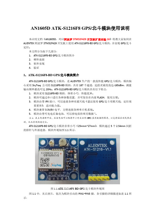
ATK-S1216F8-BD GPS/北斗模块非常小巧(25=mm*27mm) ,模块通过 5 个 2.54mm 间距 的排针与外部连接,模块外观如图 1.1 所示:
图 1.1 ATK-S1216F8-BD GPS/北斗模块外观图 图 1.1 中,从右到左,依次为模块引出的 PIN1~PIN5 脚,各引脚的详细描述如表 1.1 所 示:
3、软件实现
本实验,我们在阿波罗 STM32F429 开发板扩展实验 1:ATK-HC05 蓝牙串口模块实验 的基础上修改,本例程用不到蓝牙模块,所以先删掉 hc05.c。 然后,在 HARDWARE 文件夹里面新建一个 GPS 文件夹,并新建 gps.c,gps.h 两个文 件。然后在工程 HARDWARE 组里面添加 gps.c,并在工程添加 gps.h 的头文件包含路径。 在 gps.c 里面,我们输入如下代码: #include "gps.h" #include "led.h" #include "delay.h" #include "usart3.h" #include "stdio.h" #include "stdarg.h" #include "string.h" #include "math.h" ////////////////////////////////////////////////////////////////////////////////// const u32 BAUD_id[9]={4800,9600,19200,38400,57600,115200,230400,460800,921600}; //从 buf 里面得到第 cx 个逗号所在的位置
低功耗蓝牙从模块使用说明书新版本2
芯片
说明
序 PIN1 PIN2 PIN5 PIN10 PIN11 PIN12 PIN13 PIN14
PIN15 PIN16 PIN17 PIN18 PIN19
GND VCC EN GND I/O I/O I/O I/O /RESTORE
I/O I/O I/O I/O BRTS
脚位
"ATT:OK\r\n\0"
"25","30","40","50"
"ATT:ERP\r\n\0"
设置相应的广播周期,T
"ATT:ADD-" + Data
= X * 100ms 是 Data 为自 定义广播 数
据,数据长度 L <= 16
"ATT:OK\r\n\0" "ATT:ERP\r\n\0"
"ATT:PID-" + Data
GND VCC RST EN I/O /RESTORE
BRTS
BCTS
TX RX ADC1
脚位
-
模块电源地
-
模块电源正级(2.0V-3.6V)
模块复位
-
P2.0 P1.2
P1.1
P1.2 P1.3 P1.2 P0.1
模块使能控制线,低电平有 效,带内部上拉。 恢复出厂设置或可编程双向 IO。上电后30秒内,保持此 引脚低电平5s,系统会恢复 部分参数(浅恢复),若保 持20s以上则将会恢复全部 参数(深度恢复)
物防丢报警应用);
4. 支持防劫持密码设置,修改和恢复,防止第三方恶意连接。也可不使用。独立的
蓝蜙蜆BGM113蓝牙模块无线电路板参考手册说明书

BRD4301A Reference ManualManualThe Blue Gecko family of the Silicon Labs' Bluetooth modules delivers a high-perform-ance, low energy and easy-to-use Bluetooth solution integrated into a small form factorpackage. Blue Gecko Bluetooth modules combine an integrated antenna, a high per-formance Bluetooth transceiver, an energy efficient 32-bit MCU and a ready to useBluetooth software and SDK.The ultra-low power operating modes and fast wake-up times of the Silicon Labs' ener-gy friendly 32-bit MCUs, combined with the low transmit and receive power consump-tion of the Bluetooth radio, result in a solution optimized for battery powered applica-tions.The Silicon Labs fully certified Bluetooth modules and software are designed to help de-velopers accelerate time to market and reduce development costs and compliance risksby providing a versatile, plug-and-play Bluetooth solution.Development and evaluation of the BGM113 Bluetooth module is possible by attachingthe BRD4301A board to the Wireless Starter Kit (WSTK) Mainboard. This gives accessto the WSTK display, buttons and additional features offered by using the available Ex-pansion Boards.Rev. 1.00BRD4301A Radio Board Description 1. BRD4301A Radio Board DescriptionThe BRD4301A Radio Board contains the BGM113 Blue Gecko Bluetooth Module soldered onto a carrier board with two connectors. The connectors on the carrier board are used for attaching the BRD4301A on to a Silicon Labs Wireless Starter Kit Main-board BRD4001A and together these two boards and the software in the BGM113 Module make up the Blue Gecko Bluetooth Module Wire-less Starter Kit.The BGM113 Bluetooth module and the software are designed to help developers accelerate time to market with end-product design projects. This versatile plug-and-play Bluetooth solution also reduces development costs and minimizes compliance risks. The BGM113 Module is ideal for applications requiring Bluetooth connectivity such as used in connected home, health and fitness, wearables and point-of-sale terminal applications. The BGM113 includes an energy friendly ARM Cortex M4 MCU.A major benefit offered by the BGM113 is that no RF or Bluetooth protocol expertise is required. The BGM113 can be used as a periph-eral along with an external host MCU or applications may be embedded into the built-in MCU using the Bluegiga BGScript™ scripting language. Complete standalone solutions may thus be created with minimal need for external components.1.1 BGM113 Module Block DiagramThe BGM113 Module block diagram is illustrated in the figure below.Lowest power mode with peripheral operational:EM0—ActiveEM2—Deep SleepEM1—Sleep EM4—Hibernate EM4—ShutoffEM3—StopFigure 1.1 Block Diagram| Smart. Connected. Energy-friendly.Rev. 1.00 | 12. System SummaryIntegrated Bluetooth radio and energy friendly MCU•Bluetooth 4.1 compliant and upgradeable to Bluetooth 4.2.•TX power up to +3 dBm•RX sensitivity down to -93 dBm•Integrated high-efficiency chip antenna•38.4 MHz Cortex M4 with DSP instructions and floating-point unit for efficient signal processing•256 kB Flash memory•32 kB RAMLow Energy Consumption•8.8 mA TX current @ 0 dBm•8.7 mA RX current•63 μA/MHz in Energy Mode 0 (EM0)• 1.4 μA EM2 Deep Sleep Current (full RAM retention) and CRYO timer running from ULFRCO• 1.1 μA EM3 Stop current (State/RAM retention, RFSENSE disabled)•Wake on Radio with signal strength detection, preamble pattern detection, frame detection and timeoutWide selection of MCU peripherals•12-bit 1 Msamples/s ADC• 2 x Analog comparator•IDAC (current output DAC)•Up to 14 pins connected to analog channels (APORT) shared between analog comparators, ADC and IDAC •14 General Purpose I/O pins with output state retention and asynchronous interrupts•8-channel DMA controller•12-channel Peripheral Reflex System•Hardware Crypto Acceleration with public key support•Protocol Timer tightly coupled to the radio• 2 x 16-bit Timer/Counter• 3 + 4 Compare/Capture/PWM Channels•32-bit Real Time Counter and Calendar•16-bit Low Energy Timer for waveform generation•16-bit Ultra Low Energy Timer/Counter for periodic wake-up from any Energy Mode•16-bit Pulse Counter with asynchronous operation•Watchdog Timer with dedicated RC Oscillator @ 50 nA• 2 x Universal Synchronous/Asynchronous Receiver/Transmitter (UART/SPI/Smart Card (ISO 7816) / IrDA/I2S)•Low Energy UART (LEUART)•I²C interface with SMBus support and address recognition in EM3 StopIntegrated Bluetooth Smart Software•Bluetooth 4.1 compliant•Central and peripheral roles•Up to 8 simultaneous connections•L2CAP, ATT, GAP, SM and GATT•Any GATT based Bluetooth Smart profile•100 kbps throughputFlexible easy to use APIs•BGAPI™ serial protocol API over UART for modem usage•BGLIB™ host API/library which implementing BGAPI serial protocol•BGScript™ scripting language for standalone usage•Profile Toolkit for creating GATT based servicesFree Software Development Kit (SDK)•BGLIB C source code•BGScript development tools•BGScript and BGLIB example applications•Profile Toolkit examples•DocumentationCertifications•Bluetooth qualified (pending)•CE, FCC, IC, Japan and South-Korea (pending)Wide Operating Range•Supply voltage: 1.85 V to 3.8 V with DC/DC bypass mode •Supply voltage: 2.4 V to 3.8 V with DC/DC enabled •Temperature range: -40°C to +85°C3. BRD4301A Connector3.1 BRD4301A Connector Pin AssociationsThe figure below shows the pin mapping on the connector to the radio pins and their corresponding function on the Wireless Starter Kit Mainboard.GNDF9 / PF3 / VCOM_RTS 3v3NC / P36P200Upper RowNC / P38NC / P40NC / P42NC / P44DBG_SWDIO / PF1 / F0NC / F14BUTTON0 / PD14 / F12LED0 / PD14 / F10VCOM_CTS / PF2 / F8DBG_RESET / F4NC / F2NC / F16VCOM_TX / PA0 / F6PTI_DATA / PB12 / F20NC / F18USB_VBUS5VBoard ID SCLGNDBoard ID SDAUSB_VREG F7 / PA1 / VCOM_RX F5 / tied high / VCOM_ENABLE F3 / NCF1 / PF0 / DBG_SWCLK P45 / NCP43 / NC P41 / NC P39 / NC P37 / tied high / SENSOR_ENABLE F11 / PD15 / LED1F13 / PD15 / BUTTON1F15 / NC F17 / NCF19 / PB13 / PTI_FRAME F21 / NC GNDVMCU_INEXP3 / PF2 / P0P201Lower RowEXP5 / PF3 / P2NC / P4NC / P6GNDVRF_INP35 / NC P7 / PD13 / EXP10P5 / PB13 / EXP8P3 / PB12 / EXP6P1 / PB11 / EXP4P33 / NC P31 / NC P29 / NC P27 / PF1P25 / PF0P23 / PD15P21 / PD14P19 / NC P17 / NC P15 / NC P13 / PC10 / EXP16P11 / PA1 / EXP14P9 / PA0 / EXP12NC / P34NC / P32NC / P30NC / P28NC / P26NC / P24NC / P22NC / P20NC / P18NC / P16NC / P14EXP15 / PC11 / P12NC / P10NC / P8Figure 3.1 Radio Board Connectors3.2 BRD4301A Connector TypeBRD4301A contains two dual-row, female socket, 0.05" pitch polarized connectors (P/N: SFC-120-T2-L-D-A-K-TR) which provide the interface to the Wireless Starter Kit Mainboard. The Mainboard has the corresponding male header pin connectors (P/N: TFC-120-02-F-D-LC-ND).BRD4301A ConnectorMechanical Details 4. Mechanical DetailsModule board is illustrated in the figures below.The BGM113 BluetoothFigure 4.1 BRD4301A Top View Array Figure 4.2 BRD4301A Bottom ViewRev. 1.00 | 5Board Revision History and Errata 5. Board Revision History and Errata5.1 Revision HistoryRadio Board revision is printed on the backside of the BRD4301A Radio Board.Table 5.1. Radio Board Revision History5.2 ErrataRev. A00No known errata for this board revision. | Smart. Connected. Energy-friendly.Rev. 1.00 | 6Document Revision History 6. Document Revision HistoryRevision 1.002015-07-08Initial document revision.Silicon Laboratories Inc.400 West Cesar Chavez Austin, TX 78701USASmart.Connected.Energy-Friendly .Products/productsQuality /qualitySupport and CommunityDisclaimerSilicon Laboratories intends to provide customers with the latest, accurate, and in-depth documentation of all peripherals and modules available for system and software implementers using or intending to use the Silicon Laboratories products. Characterization data, available modules and peripherals, memory sizes and memory addresses refer to each specific device, and "Typical" parameters provided can and do vary in different applications. Application examples described herein are for illustrative purposes only. Silicon Laboratories reserves the right to make changes without further notice and limitation to product information, specifications, and descriptions herein, and does not give warranties as to the accuracy or completeness of the included information. Silicon Laboratories shall have no liability for the consequences of use of the information supplied herein. This document does not imply or express copyright licenses granted hereunder to design or fabricate any integrated circuits. The products are not designed or authorized to be used within any Life Support System without the specific written consent of Silicon Laboratories. A "Life Support System" is any product or system intended to support or sustain life and/or health, which, if it fails, can be reasonably expected to result in significant personal injury or death. Silicon Laboratories products are not designed or authorized for military applications. Silicon Laboratories products shall under no circumstances be used in weapons of mass destruction including (but not limited to) nuclear, biological or chemical weapons, or missiles capable of delivering such weapons.Trademark InformationSilicon Laboratories Inc.® , Silicon Laboratories®, Silicon Labs®, SiLabs® and the Silicon Labs logo®, Bluegiga®, Bluegiga Logo®, Clockbuilder®, CMEMS®, DSPLL®, EFM®, EFM32®, EFR, Ember®, Energy Micro, Energy Micro logo and combinations thereof, "the world’s most energy friendly microcontrollers", Ember®, EZLink®, EZRadio®, EZRadioPRO®, Gecko®, ISOmodem®, Precision32®, ProSLIC®, Simplicity Studio®, SiPHY®, Telegesis, the Telegesis Logo®, USBXpress® and others are trademarks or registered trademarks of Silicon Laborato-ries Inc. ARM, CORTEX, Cortex-M3 and THUMB are trademarks or registered trademarks of ARM Holdings. Keil is a registered trademark of ARM Limited. All other products or brand names mentioned herein are trademarks of their respective holders.。
蓝牙音频立体声发射串口AT芯片模块的flash简单使用说明

一、简介蓝牙发射芯片KT1025A支持的音源如下:蓝牙发射支持的音源原理1、支持发射AUX的音频这个是先采样为数字信号,转成SBC蓝牙发出去2、支持发射U盘TF卡或者spiflash的音频这个是数字信号直接转换为SBC蓝牙发出去3、支持发射PC声卡的音源这个是数字信号直接转换为SBC蓝牙发出去备注:支持是芯片支持,但是受限于软件,可能些许功能是不能同时使用的,后面详细说明二、简单操作说明1.1芯片上电返回的信息芯片上电会主动的返回一些信息,具体的查找手册,可以不用关注1.2蓝牙连接---随机搜索---最简单的使用方式1、如果是简单的应用,直接让芯片进入随机搜索就可以,他会直接进入搜索状态,搜索到谁就连谁2、芯片上电,如果是发射模式,芯片会自动进入空闲,等待用户发送指令1.3蓝牙连接---指定地址去连接---比较复杂1、这个详细的可以看看手册2、简单来说,就是先搜索周围的设备,获取名字和MAC地址,然后再指定MAC地址去连接1.4蓝牙发射的音源说明1、优先级:U盘>TF>flash>AUX>PC2、如果连接成功之后,会依次按照如上的顺序去初始化设备,然后播放音乐,同时发射音源1.5蓝牙发射的一些内部操作说明1、蓝牙在发射状态,他的搜索流程是,简单来讲就是如下的方式:(1)、芯片接收到相对应的指令之后,会主动发起搜索,同时会自动开始计时。
时间限定为6秒钟左右(2)、芯片在搜索的过程中,会不断的发现周边的设备,和你手机其实是一样方式,只是没有显示屏而已(3)、如果设定的时间到了,蓝牙芯片就超时了:==>如果芯片是随机搜索,那么即使超时了,他也会再次发起搜索并连接==>如果是芯片只是为了查找周边的设备,那么他超时就停止了==>如果他是指定MAC地址去连接,那么他超时之后,也会继续发起搜索并连接(4)、同时发起搜索,搜索停止等等状态,都是可以通过指示灯或者串口查看的,详细的请查阅手册1.6测试注意事项1、重点关注指示灯的状态:常亮、慢闪、超快闪2、常亮代表连接成功,超快闪就代表搜索中,慢闪基本就是空闲。
蓝牙模块使用说明书
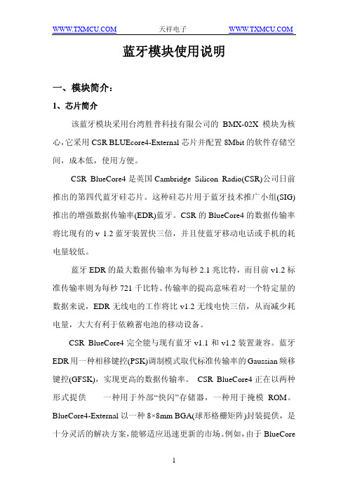
蓝牙模块使用说明一、模块简介:1、芯片简介该蓝牙模块采用台湾胜普科技有限公司的BMX-02X模块为核心,它采用CSR BLUEcore4-External芯片并配置8Mbit的软件存储空间,成本低,使用方便。
CSR BlueCore4是英国Cambridge Silicon Radio(CSR)公司日前推出的第四代蓝牙硅芯片。
这种硅芯片用于蓝牙技术推广小组(SIG)推出的增强数据传输率(EDR)蓝牙。
CSR的BlueCore4的数据传输率将比现有的v 1.2蓝牙装置快三倍,并且使蓝牙移动电话或手机的耗电量较低。
蓝牙EDR的最大数据传输率为每秒2.1兆比特,而目前v1.2标准传输率则为每秒721千比特。
传输率的提高意味着对一个特定量的数据来说,EDR无线电的工作将比v1.2无线电快三倍,从而减少耗电量,大大有利于依赖蓄电池的移动设备。
CSR BlueCore4完全能与现有蓝牙v1.1和v1.2装置兼容。
蓝牙EDR用一种相移键控(PSK)调制模式取代标准传输率的Gaussian频移键控(GFSK),实现更高的数据传输率。
CSR BlueCore4正在以两种形式提供——一种用于外部“快闪”存储器,一种用于掩模ROM。
BlueCore4-External以一种8×8mm BGA(球形格栅矩阵)封装提供,是十分灵活的解决方案,能够适应迅速更新的市场。
例如,由于BlueCore是目前可以得到的唯一能够支持蓝牙v1.2规格的所有强制和可选功能的硅芯片,BlueCore4-External为PC应用程序提供了理想的解决方案,使它们得益于以三倍速度的传输率无线传输文件,或者同时操作多个高需求的蓝牙链路。
鉴于蓝牙固件安装在芯片只读存储器上,CSR BlueCore4-ROM 的成本较低,占用面积小得多(在小片尺寸包装中为3.8×4mm,在与BC2-ROM和BC3-ROM引脚兼容的BGA中为6×6mm)。
蓝牙模块应用必读

蓝牙模块应用必读
双击自动滚屏发布者:admin 发布时间:2008-3-12 10:49:48 【字体:大中小】
购买蓝牙模块的用户,使用中请注意以下几点:
1、供电问题:蓝牙模块供电为3.3V,百米蓝牙模块供电采用两级供电,包括VCC和PAVCC,其中PAVCC 是功率扩展电源,使用中一定要两个都供给3.3V。
2、接地问题:模块中有多个GND引脚,使用中应将全部GND接地。
3、PIO引脚指示问题:在模块应用中,有的PIO是蓝牙模块工作状态指示,建议您最少引出一个做为工作状态监测引脚,如PIO5,未建链时输出800ms的脉冲信号,建链后输出200ms的脉冲信号,详细引脚功能定义请参考相应免费蓝牙固件应用说明。
4、音频应用:
音频应用中,如果您的电路板上有别的音频电路,建议将蓝牙模块单独稳压供电,减少干扰噪声。
蓝牙模块的MIC输入与SPK输出采用平衡电路接法,与外围电路连接时需要平衡非平衡转换器件,详细请看最新音频电路参考设计。
5、不用的引脚:模块中可能有许多你不需要的引脚,不用的引脚一律悬空。
6、SPI接口:SPI接口是模块固件升级和参数修改有接口,共4条线,在布设PCB板时,建议引出焊盘,便于今后固件维护。
7、GC-05/06的兼容问题:GC-05是百米蓝牙模块,GC-06是10米蓝牙模块,两者引脚完全兼容,建议您在PCB布板时,按GC-05设计,然后按需要插入GC-05、06都可以,这样在产品应用中更换10米100米不同功率的模块时,更方便。
维亚思控制器蓝牙模块使用说明书

维亚思控制器蓝牙模块使用说明书(原创版)目录1.维亚思控制器蓝牙模块概述2.蓝牙模块的功能特点3.蓝牙模块的安装与连接4.蓝牙模块的使用方法5.蓝牙模块的注意事项6.蓝牙模块的故障排除与维护正文一、维亚思控制器蓝牙模块概述维亚思控制器蓝牙模块是一款功能强大、易于使用的蓝牙设备,适用于各种需要无线连接的场景。
该模块采用了先进的蓝牙技术,具有较高的稳定性、可靠性和兼容性,可与市面上大部分蓝牙设备连接。
二、蓝牙模块的功能特点1.高稳定性:维亚思控制器蓝牙模块采用了高性能的蓝牙芯片,确保了在各种环境下都能保持稳定连接。
2.高兼容性:模块支持蓝牙 4.0 及以上版本,可与市面上大部分蓝牙设备无缝连接。
3.低功耗:模块具有低功耗特性,即使长时间使用也不会对设备的续航造成明显影响。
4.多功能:模块支持数据传输、音频传输等多种功能,满足不同场景的需求。
三、蓝牙模块的安装与连接1.安装:蓝牙模块采用标准接口设计,可轻松插入设备的相应接口进行安装。
2.连接:安装完成后,打开设备的蓝牙设置,搜索附近的蓝牙设备,找到模块的设备名称并点击连接,即可完成配对。
四、蓝牙模块的使用方法1.数据传输:连接成功后,可通过蓝牙模块在设备间传输数据,如文件、图片等。
2.音频传输:模块支持音频传输功能,可连接蓝牙耳机、音响等设备播放音乐、接听电话等。
五、蓝牙模块的注意事项1.请勿将蓝牙模块置于潮湿、高温的环境中,以免损坏设备。
2.在使用过程中,请勿让模块受到强烈撞击或摔落,以免影响使用寿命。
3.如有异常现象,请立即断开电源并联系售后服务。
六、蓝牙模块的故障排除与维护1.若连接过程中出现配对失败,请尝试重新开启蓝牙设备或重新安装模块。
2.若传输数据时出现中断或速度慢,请检查蓝牙设备之间的距离是否过远,或尝试更换传输方式。
- 1、下载文档前请自行甄别文档内容的完整性,平台不提供额外的编辑、内容补充、找答案等附加服务。
- 2、"仅部分预览"的文档,不可在线预览部分如存在完整性等问题,可反馈申请退款(可完整预览的文档不适用该条件!)。
- 3、如文档侵犯您的权益,请联系客服反馈,我们会尽快为您处理(人工客服工作时间:9:00-18:30)。
ATK-SPP蓝牙串口说明书
ATK-SPP 蓝牙数传模块
一.模块概述
ATK-SPP是一款专为数据传输设计的蓝牙模块,遵循
蓝牙
3.0协议。
支持SPP蓝牙串口协议,支持UART接口。
具
有成本低,兼容性好,功耗低等优点。
二.应用领域
1 蓝牙打印机
2 蓝牙遥控玩具
3 智能家居
4 汽车诊断仪
5 蓝牙无线数据传输
6 蓝牙游戏手柄
7 无线数据传输
8 蓝牙GPS
9 工业遥
控
三.引脚说明
引脚引脚功能描述
1 VCC 3.3V电源
2 P00 LED
3 P01 I/O
4 P30 I/O
5 P35 I/O
6 P45 I/O
7 GND 电源地
8 GND 电源地
9 P10 I/O
10 P20 UART-RXD
11 P21 UART-TXD
12 P22 I/O
13 P23 I/O
14 P24 I/O
15 P25 I/O
16 P26 I/O或者PWM口
17 NC 悬空
18 P11 I/O
四.模块尺寸
尺寸大小:12.7x23.4x1mm Pcb pad layout size是 1.5×1mm
五.应用电路
六.命令参数
1.设置命令:#AT#SET=m#
#:特征码
m:0退出命令设置模式
1-9进入命令设置模式,1代表5S,2代表10S,依
此类
推,最大可以设置45S。
这个数字表示在该时间内没
有输
入命令或者收到错误的命令,自动退出设置模式。
命
令的
设置需要蓝牙连接成功以后,用终端去设置,例如手
机,
电脑等。
只有使用该命令进入到设置模式后,其它命
令才
有效。
收到正确命令后返回“OK”。
例:#AT#SET=3#进入设置模式15S
#AT#SET=0# 退出设置模式
2.修改蓝牙名字:#AT#NAME=nnnnn#
蓝牙名字最长位数为32位字符,修改成功后返回“OK”。
例:#AT#NAME=BLUETOOTH# 蓝牙名字改为:
BLUETOOTH,重新上电后生效。
3.修改配对密码:
#AT#PIN=xxxx#
密码长度为4个数字,修改成功后返回“OK”。
例:#AT#PIN=0000# 蓝牙密码改为:0000,重新上电
后生
效。
4.修改蓝牙MAC地址:#AT#MAC=xxxxxxxxxxxx#
蓝牙地址为6个字节,修改成功后返回“OK”。
例:#AT#MAC=123456ABCDEF# 蓝牙MAC地址改为:12:34:56:AB:CD:EF,重新上电后生效。
5.获得当前模块配置:#AT#GET#
模块会返回蓝牙名字,MAC地址,密码,串口设置信
息。
例:
N:BULETOOTH
MAC:11:22:33:44:55:66
P:0000
UART:115200,8,NONE,1
6.串口设置命令:#AT#UART=B,S#
B的范围0-8
0-
2400BPS
1-4800BPS
2-9600BPS
3-19200BPS
4-38400BPS
5-57600BPS
6-115200BPS
7-128000BPS
8-256000BPS
S的范围0-2
0:无检验位
1:奇检验
2:偶检验
修改成功后返回“OK”。
例:#AT#UART=3,2# 串口修改为,波特率19200,8
位数据
位,偶检验
默认串口设置是:115200,8位数据位,无检验位。
本产品为蓝牙3.0类产品,可以和大部分安卓手
机平板已经PC机通讯
在本产品资料包里有安卓测试APK安装包
下载蓝牙串口通信助手:
/apps/mobi.dzs.android
.BluetoothSPP
带有蓝牙的电脑也可以和本模块通讯
首先打开电脑主机或手机端,打开蓝牙功能,去搜索周边设备当搜到BLUE_SPP本模块默认设备名字后,即可链接,配对密码是1234 。
链接成功后手机或电脑会自动保存到系统中。
然后安装手机端APK SPP类测试工具(蓝牙串口通讯助手)。
打开蓝牙串口助手后,先和刚才已经搜索到的设备连接,链接成功后,即可在这个蓝牙串口通讯工具中向我们的蓝牙模块收发数据了!蓝牙模块收到数据后,经过串口输出单片机即可收到数据了,默认波特率是115200。