WGB-871技术及使用说明书
北方工具和设备产品说明书:通道管

Telescopic CylinderOwner’s ManualWARNING: Read carefully and understand all ASSEMBLY AND OPERATION INSTRUCTIONS before operating. Failure to follow the safety rules and other basic safety precautions may result in serious personal injury.Items #66735, #66736, #66738, #66739, #66740, #66741, #66742, #66743, #66744, #66745Thank you very much for choosing a NorTrac™ product!For future reference, please complete the owner’s record below:Serial Number/Lot Date Code: ________________________________ Purchase Date: ____________________________________________ Save the receipt, warranty, and this manual. It is important that you read the entire manual to become familiar with this product before you begin using it.This telescopic cylinder is designed for certain applications only. Northern Tool and Equipment is not responsible for issues arising from modification or improper use of this product such as an application for which it was not designed. We strongly recommend that this product not be modified and/or used for any application other than that for which it was designed.For technical questions, please call 1-800-222-5381.Intended Use (4)Packaging Contents (4)Technical Specifications (4)Important Safety Information (4)Specific Operation Warnings (6)Main Parts of Telescopic Cylinder (6)Assembly Instructions (6)Operating Instructions (14)After Each Use (17)Maintenance (17)Troubleshooting (18)Parts Diagram (18)Parts List (19)Replacement Parts (19)Limited Warranty (20)The NorTrac series telescopic cylinders are ideal for construction, mining, forestry, marine, demolition, military, material handling, agriculture, truck and trailer, loader, utility, and waste management.•Telescopic Cylinder •Owner’s ManualCylinder DisassemblyBefore Disassembling the Cylinder•Dismantle the cylinder in a clean location.•Each part should be thoroughly cleaned. If the cylinder is to be dismantled for any length of time, coat the metal parts, which are to be reused with a good rust inhibitor and store them in aprotected area.Disassembling the Cylinder1. Un-thread the top screw on the rear cap (#23).2. Remove the rear cap.3. Drain the oil inside.4. Knock the trunnion (#31) to force the inner piston rod (#32) out.5. Take out the piston rod (includes a larger and smaller one).6. Knock the inside edge of the piston rod to find the correct position of the inner support ring.7. Remove the support ring.8. Punch holes into the back of the inner groove.9. You may also drill holes with a power drill.10. Rotate the inner back-up ring hole at an angle (using the process above) to remove the innerback-up ring (#9).11. Take out the two piston rods inside.12. Repeat steps 8, 9, and 10. Remove the back-up ring (#9) from the larger piston rod.13. Take out the smaller piston rod.14. Remove the #8, the #16, and the #19 BS seals from the larger and smaller piston rod.15. The #18 back-up ring is at the other end of the piston rod. See the image below.Reassembly Procedures1. Place the 3rd stage tube (#2) back inside the outer tube assembly (#1) and install the collar (#6).2. Place the 2nd stage tube (#3) inside the 3rd stage tube (#2) and install the collar (#7).3. Re-thread the rod end (#13) onto the 1st stage tube (#4) and put the 1st stage tube (#4) into thecylinder. Be careful not to damage the seals while installing each tube.4. Thread the rear cap (#23) onto the cylinder and tighten the hex set screw (#26).Operating Conditions•The maximum operating pressure must not exceed 2500 PSI.•The contamination level of the oil must not exceed 16/13/10 from the ISO standard 4406. •The acceptable temperature range is -40° F to 200° F.Formula for Calculating the Initial Required Cylinder Force to Lift a Load:A = the distance from the center of the load to the center of the dump body hinge pin (inches)B = the length from the center of the cylinder base pin to the center of the dump body hinge pin (inches)Load (lb.) x A /B = Initial required cylinder force (lb.)Example:50,000 (lb.) x 85"/166” =25,602 lb. = Initial required force (lb.)B = The length of cylinder base pin to body hinge pin D = Dump Angle CoefficientB X D = Approximate Required StrokeExample:166(B) X 845(D)= 140 Approximate Required Stroke•When the cylinder is not in use it should be fully retracted to prevent the chromed cylinder shaft from becoming damaged.•Always store the cylinder inside to protect it against harsh weather conditions.•Fill the cylinder with oil to prevent internal corrosion caused by air condensation. Tilt the cylinder to make sure that all seals are completely in contact with the oil to avoid any prematuredeterioration of the seals.•Cover any unpainted part with a rust inhibitor to avoid corrosion.•Regularly grease the trunnion pins. The time between greasing will be dependent on the amount the cylinder is used. Improper lubrication will result in the pins wearing prematurely.•For replacement parts and technical questions, please call Customer Service at 1-800-222-5381. •Not all product components are available for replacement. The illustrations provided are a convenient reference to the location and position of parts in the assembly sequence.•When ordering parts, the following information will be required: item description, item model number, item serial number/item lot date code, and the replacement part reference number. •The distributor reserves the rights to make design changes and improvements to product lines and manuals without notice.Northern Tool and Equipment Company, Inc. ("We'' or "Us'') warrants to the original purchaser only ("You'' or "Your") that the NorTrac product purchased will be free from material defects in both materials and workmanship, normal wear and tear excepted, for a period of two years from date of purchase. The foregoing warranty is valid only if the installation and use of the product is strictly in accordance with product instructions. There are no other warranties, express or implied, including the warranty of merchantability or fitness for a particular purpose. If the product does not comply with this limited warranty, Your sole and exclusive remedy is that We will, at our sole option and within a commercially reasonable time, either replace the product or product component without charge to You or refund the purchase price (less shipping). This limited warranty is not transferable.Limitations on the WarrantyThis limited warranty does not cover: (a) normal wear and tear; (b) damage through abuse, neglect, misuse, or as a result of any accident or in any other manner; (c) damage from misapplication, overloading, or improper installation; (d) improper maintenance and repair; and (e) product alteration in any manner by anyone other than Us, with the sole exception of alterations made pursuant to product instructions and in a workmanlike manner.Obligations of PurchaserYou must retain Your product purchase receipt to verify date of purchase and that You are the original purchaser. To make a warranty claim, contact Us at 1-800-222-5381, identify the product by make and model number, and follow the claim instructions that will be provided. The product and the purchase receipt must be provided to Us in order to process Your warranty claim. Any returned product that is replaced or refunded by Us becomes our property. You will be responsible for return shipping costs or costs related to Your return visit to a retail store.Remedy LimitsProduct replacement or a refund of the purchase price is Your sole remedy under this limited warranty or any other warranty related to the product. We shall not be liable for: service or labor charges or damage to Your property incurred in removing or replacing the product; any damages, including, without limitation, damages to tangible personal property or personal injury, related to Your improper use, installation, or maintenance of the product or product component; or any indirect, incidental or consequential damages of any kind for any reason.Assumption of RiskYou acknowledge and agree that any use of the product for any purpose other than the specifieduse(s) stated in the product instructions is at Your own risk.Governing LawThis limited warranty gives You specific legal rights, and You also may have other rights which vary from state to state. Some states do not allow limitations or exclusions on implied warranties or incidental or consequential damages, so the above limitations may not apply to You. This limited warranty is governed by the laws of the State of Minnesota, without regard to rules pertaining to conflicts of law. The state courts located in Dakota County, Minnesota shall have exclusive jurisdiction for any disputes relating to this warranty.Distributed by:Northern Tool & Equipment Company, Inc.Burnsville, Minnesota 55306Made in ChinaPage 21 of 21。
870型直读式BOD5测定仪说明书

870型直读BOD5测定仪说明书南京科环分析仪器有限公司目录一、仪器简介及使用范围 (1)二、工作原理 (1)三、环境条件和主要技术指标 (2)四、仪器的组成 (2)五、安装和使用 (2)六、分析方法及分析步骤 (4)七、正常维护和常见故障的排除 (10)八、运输和贮存 (12)九、注意事项……………………………………………………………………l2十、870直读BOD5测定仪装箱清单 (14)十一、产品使用信息反馈单 (15)597一、仪器简介及使用范围生物化学需氧量BOD5是水质评价的必测项目,是衡量有机物对水质污染的重要质量指标。
传统BOD5的测定方法采用化学稀释法。
该方法操作繁琐,对分析人员的实验技能要求较高,实验数据的离散性较大,往往造成无法得出准确的实验结果。
870型直读式BOD5测定仪是利用空气压差法进行生化需氧量测定的一种新型仪器,其操作简单,能提供与化学稀释法可比的准确测量结果,读数直观,使用和维护方便。
广泛应用于环保监测、石油化工、医疗卫生、教学科研等部门对水质的监测,是广大分析工作者的有力工具。
二、工作原理1、B0D5基本原理生化需氧量(英文缩写BOD),是指在特定条件下,通过水中需氧微生物的繁殖和呼吸作用,分解水中有机物质时所消耗或所需要溶解氧量。
水中的BOD5值通常以样品在20℃放置5天所消耗溶解氧的量(mg/L数)表示,记为“BOD5”。
2、测定原理将预先选好量程并按量程范围量好体积的水样倒入培养瓶中,在主机搅拌器上连续搅拌。
并将主机和培养瓶放入培养箱中。
调节培养箱内温度为20℃±1℃,待样品恒温后进行五日培养。
培养瓶中的水样在连续搅拌的情况下保证了足够的溶解氧供微生物进行生化反应。
水样中的有机物经过生物氧化作用,转变成氮、碳和硫的氧化物。
在这一过程中,从水样中溢出的唯一气体二氧化碳被氢氧化钠(或氢氧化钾)吸收。
此时,培养瓶中空气压力减少量,相当于微生物所消耗的溶解氧含量,即水样BOD5值与瓶中空气压力减少的程度成正比,所以BOD5的值可以由空气压力减少值来测定,增加或减少所取样品的量可以增加或降低压力减少值。
WGB 技术及使用说明书

WGB-871微机综合保护装置技术说明书(Ver )许继电气股份有限公司XJ ELECTRIC CO.,LTD.本装置为微机综合保护装置,根据软件的不同配置可实现对线路、电动机、电容器及厂用变的保护,装置在出厂时默认设置为线路保护,在实际使用时请用户务必将装置类型设置为工程所需;具体设置方法如下:目录1概述1.1应用范围WGB-871微机综合保护装置适用于10kV及以下变电站配电所,可根据使用场合灵活将装置配置为线路保护测控装置、电容器保护测控装置、厂用变保护测控装置、电动机保护测控装置。
线路保护测控装置适用于3~10kV的馈出线保护;厂用变保护测控装置适用于3~10kV电压等级的厂用变、所用变或接地变的保护;电容器保护测控装置适用于10kV及以下变电站或配电所装设的并联电容器的保护;电动机保护测控装置适用于3~10kV电压等级2000kW以下中小型异步电动机的保护。
1.2产品特点✧系列装置元器件全部采用军品或工业品,稳定性、可靠性高,可以在工业恶劣环境下稳定运行;✧一体化机箱设计,维护更方便;完善的软硬件自检功能和免调节电路设计,调试更简单;✧装置硬件设计采用多种隔离、屏蔽措施,软件设计采用数字滤波技术和先进的保护算法及其它抗干扰措施,使得保护的抗干扰性能大大提高;✧采用SoC解决方案,数据处理、逻辑运算和信息储存能力强,运行速度快,可靠性高;✧灵活强大的通信功能:既支持RS485串行通信模式也支持以太网通信模式;通信规约支持DL/T667-1999(IEC-60870-5-103)、Modbus规约,可灵活实现与其它厂家的自动化系统通信;✧灵活支持网络对时和GPS脉冲对时,保证装置具有统一、准确的时钟;✧具有完善的测量功能,可完成装置所在间隔功率点的测量和上送,测量精度可达±%;✧具有完善的遥信和遥控功能,后台遥控断路器跳/合闸简单可靠,站内SOE分辨率可达1ms;✧完善的事件保护处理,可存储最新100条事件报告记录,100条动作报告记录,可连续记录20个故障录波,每个录波可记录10个周波的电流电压波形;✧友好的人机界面,全中文类菜单模式,结构清晰,使用方便;✧操作回路配置灵活,可以适应各种操作机构。
天津市精工医疗设备技术 数控超声波清洗器 说明书

使用说明书天津市精工医疗设备技术有限公司TianjinJing-GongMedicalEquipment&TechnologyCo.,Ltd.1主要性能及特点●●●本仪器加热到设定温度后自动超声。
电气控制板全密封薄膜开关及数码显示功能。
数显记忆设定的超声工作时间●●数显记忆设定的超声功率。
数显记忆设定的加热温度和当前容器内的实际温度。
设备安装●●●开箱后先阅读使用说明书,检查使用说明书最后一页附件单上的附件是否齐全,设备在运输过程中是否损坏,如发现损坏或缺货及时与本公司联系。
仪器安装在平整的桌面,环境保持干燥,通风。
本仪器电源线接入220V/50Hz三芯电源开关箱内,但必须有接地装置。
必须使用方法1.将需清洗的物件放入清洗网架,同时放入清洗槽内,绝对不能将物件直接放入清洗槽内,以免影响清洗效果,同时防止损坏仪器。
2.清洗槽内的水或水溶液不得低于50mm,而最高不得超过80mm。
3.按比例放入清洗剂。
4.打开背面电源开关,显示器上显示000,按ON键,开始设定:按时间键,时间指示灯亮,显示器显示的数字是上次设定的超声时间,按∧∨键设定所需超声时间。
5.按温度键,温度指示灯亮,显示器显示的是上次设定的温度,按∧∨键设定所需温度。
6.按超声键,超声指示灯亮,显示器显示的是上次设定的超声功率,按∧∨键设定超声功率,从50%-100%。
7.设定好后,按ON/OFF键,仪器开始自动加热,显示器显示为实际加热温度,当达到所设温度时,超声自动开启。
8.超声工作时,若想了解所设超声时间剩多少,按时间键,显示器显示所剩时间,显示5秒后恢复到超声功率。
9.超声工作时,若想了解温度多少,按温度键,显示器显示实际温度,显示5秒后恢复到超声功率。
10.所有设定必须在超声开启之前设定完毕,否则温度和时间设定无效,请注意微处理器将记忆最后一个输入的设定数字。
11.清洗完毕后,从清洗槽内取出网架,用温水漂洗,再用热风干燥或擦干,同时再把未清洗的物件放入超声清洗槽内,按超声键即可。
罗克威尔自动化871TM系列电磁感应接近传感器说明书
EU Declaration of Conformity Product: Inductive Proximity SensorsName and address of the manufacturer: Rockwell Automation Inc.1201 South 2nd StreetMilwaukee, WI 53204U.S.A. Name and address of the authorised representative: Rockwell Automation NVPegasus ParkDe Kleetlaan 12A1831 DiegemBelgiumThis declaration of conformity is issued under the sole responsibility of the manufacturer.Object of the declaration: Allen-Bradley 871TM Series(reference the attached list of catalogue numbers)The object of the declaration described above is in conformity with the relevant Union harmonization legislation: 2014/35/EU Low Voltage Directive (LVD)2014/30/EU EMC Directive (EMC)2011/65/EU (incorporating 2015/863) RoHS Directive (RoHS)References to the relevant harmonized standards used or references to the other technical specifications in relation to which conformity is declared:EN 60947-5-2:2007 + A1:2012 Low voltage switchgear and controlgear – Part 5-2: Control circuit devicesand switching elements – Proximity switchesEN 63000:2018 Technical documentation for the assessment of electrical and electronicproducts with respect to the restriction of hazardous substancesSigned for and on behalf of the above named manufacturer:Place and date of issue:Milwaukee, WI USA 05-Jun-2023Name, function:Daniel L. Nachtigall, Technical Leader – Product Compliance Engineering Signature:number is given, then all series are certified.2) Yes = Product is certified to this directive.N/R = This directive is not required for this product.NOMENCLATURE:。
许继WGQ871说明书

WGQ-871 型微机故障启动装置
各带电的导电电路分别对地(即外壳或外露的非带电金属零件)之间,交流 回路与直流回路之间,用开路电压为 500V 的测试仪器测试其绝缘电阻值应不小 于 100MΩ。 2.2.13.2 介质强度 各带电的导电电路分别对地(即外壳或外露的非带电金属零件)之间,交流回路 与直流回路之间,能耐受交流 50Hz、电压 2kV(有效值),历时 1min 试验,而无绝 缘击穿或闪络现象。 2.2.13.3 冲击电压
IV87系列说明书8711(修改)

4.1.1 定电流操作模式(CC) ............................................................................................. 9 4.1.1.1 标准定电流模式................................................................................................... 9 4.1.1.2 加载卸载定电流模式............................................................................................ 9 4.1.1.3 软启动定电流模式 ............................................................................................. 14 4.1.1.4 定电流转定电压模式.......................................................................................... 15
种子处理机说明书
激光种子处理机技术领域本发明涉及激光种子处理机,属农用机电设备领域。
背景技术目前,我国广大农村在播种农作物之前,大都对种子不进行处理,因此农作物会出现抗寒、抗旱、抗盐碱、抗病虫害能力弱的问题,由于农作物的抗逆性不足,所以当天时、地利逆变时容易使农作物减产。
发明内容为解决上述背景技术问题的现状,本发明激光种子处理机,把播种前的种子先经过适当强度的激光辐射,播种后可以提高种子的萌发率、提高酶的活性和叶绿素的含量,从而提高农作物的营养成分及农作物的抗逆性,实现农作物的增产增收,如小麦、春大麦、玉米、向日葵、萞麻子等可增产20%。
本发明的技术解决方案是,激光种子处理机它包括整流电路、超声波振荡器、升压电路、激光发生器、种子处理装置,其中:整流电路,将220V交流市电变成直流电,以供超声波振荡器电能;超声波振荡器,将直流电能转换成30KHz超声波交流电能,以提高升压效率;升压电路,将超声波电能通过超声波变压器升压,并再经倍压整流电路,变成附合激光管所需求的直流高压;激光发生器,选用二氧化碳激光管,可得到较大功率的激光光源;种子处理装置,它是一个种子处理的传送平台,让种子匀速通过激光束的照射。
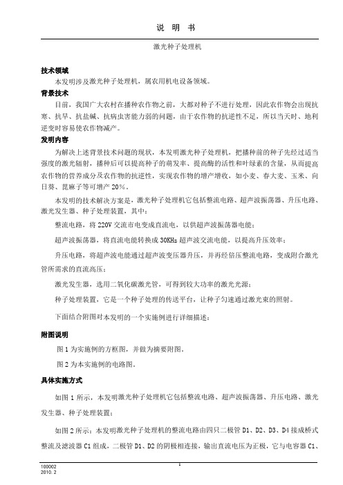
下面结合附图对本发明的一个实施例进行详细描述:附图说明图1为实施例的方框图,并做为摘要附图。
图2为本实施例的电路图。
具体实施方式如图1所示,本发明激光种子处理机它包括整流电路、超声波振荡器、升压电路、激光发生器、种子处理装置;如图2所示:本发明激光种子处理机的整流电路由四只二极管D1、D2、D3、D4接成桥式整流及滤波器C1组成,二极管D1、D2的阴极相连接,输出直流电压为正极,它与电容器C1、C3的一端及电阻R2、R4的一端和变压器绕组T1的一端相连,D3、D4的阳极连接,输出直流电压为负极,它与C1的另一端、电阻R5的一端、集成电路ic1-TLP52-1的第3脚及模拟地相连,市电220V的相线,接端子A和电阻R1的一端,R1的另一端,接D2阳极及D4阴极,市电220V的零线,接D1阳极和D3阴极;超声波振荡器,由三极管BG1、电阻R2、R3、R4、R5、 R6、R7,电容器C2、C3,二极管D5,变压器绕组T1、T2及集成电路IC1-TLP521-1,三极管BG1发射接R5的另一端,三极管BG1的基极接集成电路IC1的第4脚、R2另一端、C2的一端,C2另一端与R3的一端连接,R3的另一端与T2的一端连接,T2另一端接模拟地,二极管D5的阳极接三极管BG1集电极和变压器绕组T1的另一端,二极管D5的阴极接C3、R4的另一端,电阻R6是电流取样电阻,R7是电流整定电位器,电阻R6的一端和电位器R7的低电位端,接变压器绕组T3的一端并接地,电位端R7的动臂端接集成电路ic1-TLP52-1的第1脚. 集成电路ic1-TLP52-1的第2脚接地;升压电路,由变压器绕组T3、二极管D6、D7和电容器C4 组成,变压器绕组T3的另一端接D6阳极和D7阴极,D6的阴极接电容器C4的一端,电容器C4的另一端接D7的阳极、R6的另一端和电位器R7的高电位端;激光发生器CO2JG,其阳极接线端子P接二极管D6的阴极,此端为直流高压的正极,激光发生器CO2JG的阴极接线端子E端,接二极管D7阳极,此端为直流高压的负极,激光束JlS 射向输送带上的种子Z;种子处理装置CS,它是一套传送带系统,可使种子匀速经激光处理。
- 1、下载文档前请自行甄别文档内容的完整性,平台不提供额外的编辑、内容补充、找答案等附加服务。
- 2、"仅部分预览"的文档,不可在线预览部分如存在完整性等问题,可反馈申请退款(可完整预览的文档不适用该条件!)。
- 3、如文档侵犯您的权益,请联系客服反馈,我们会尽快为您处理(人工客服工作时间:9:00-18:30)。
WGB-871微机综合保护装置技术说明书(Ver 1.00)许继电气股份有限公司XJ ELECTRIC CO.,LTD.本装置为微机综合保护装置,根据软件的不同配置可实现对线路、电动机、电容器及厂用变的保护,装置在出厂时默认设置为线路保护,在实际使用时请用户务必将装置类型设置为工程所需;具体设置方法如下:目录1 概述 ................................................................................................................................................... 错误!未定义书签。
1.1应用范围 .................................................................................................................................. 错误!未定义书签。
1.2产品特点 .................................................................................................................................. 错误!未定义书签。
1.3保护配置 .................................................................................................................................. 错误!未定义书签。
2 技术指标 ........................................................................................................................................... 错误!未定义书签。
2.1基本电气参数 .......................................................................................................................... 错误!未定义书签。
2.1.1额定交流数据 ................................................................................................................. 错误!未定义书签。
2.1.2额定电源数据 ................................................................................................................. 错误!未定义书签。
2.1.3功率消耗......................................................................................................................... 错误!未定义书签。
2.1.4过载能力......................................................................................................................... 错误!未定义书签。
2.2主要技术指标 .......................................................................................................................... 错误!未定义书签。
2.2.1保护定值整定范围及误差 ............................................................................................. 错误!未定义书签。
2.2.2测量精度......................................................................................................................... 错误!未定义书签。
2.2.3记录容量......................................................................................................................... 错误!未定义书签。
2.2.4触点容量......................................................................................................................... 错误!未定义书签。
2.2.5绝缘性能......................................................................................................................... 错误!未定义书签。
2.2.6机械性能......................................................................................................................... 错误!未定义书签。
2.2.7抗电气干扰性能 ............................................................................................................. 错误!未定义书签。
2.3环境条件 .................................................................................................................................. 错误!未定义书签。
2.4通信接口 .................................................................................................................................. 错误!未定义书签。
3 装置功能 ........................................................................................................................................... 错误!未定义书签。
3.1FC回路保护(厂用变、电动机保护配置) ......................................................................... 错误!未定义书签。
3.2(低压闭锁)过流保护(线路保护配置)........................................................................... 错误!未定义书签。
3.3复压闭锁过流保护(厂用变保护配置)............................................................................... 错误!未定义书签。
3.4过流保护(电容器、电动机保护配置)............................................................................... 错误!未定义书签。
3.5反时限过流保护(线路、厂用变、电容器、电动机保护配置) ....................................... 错误!未定义书签。
3.6过流加速保护(线路保护配置)........................................................................................... 错误!未定义书签。
3.7重合闸(线路保护配置)....................................................................................................... 错误!未定义书签。
3.8负序过流保护(厂用变、电动机保护配置)....................................................................... 错误!未定义书签。
3.9零序过流保护(线路、厂用变、电容器、电动机保护配置) ........................................... 错误!未定义书签。
3.10低压侧零序过流保护(厂用变保护配置) ...................................................................... 错误!未定义书签。
3.11低压侧零序过流反时限保护(厂用变保护配置) .......................................................... 错误!未定义书签。
3.12电动机起动超时保护(电动机保护配置) ...................................................................... 错误!未定义书签。
3.13过热保护(电动机保护配置) .......................................................................................... 错误!未定义书签。