元器件手册
电子元器件说明书
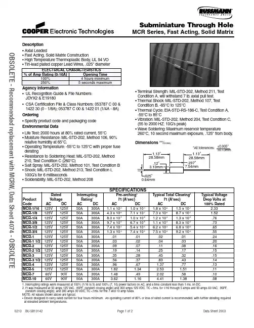
Description• Axial Leaded• Fast Acting, Solid Matrix Construction• High T emperature Thermoplastic Body, UL 94 VO • Tin-lead plated copper Lead Wires, .025" diameterAgency Information•UL Recognition Guide & File Numbers:JDYX2 & E19180•CSA Certification File & Class Numbers:053787 C 00 & 1422 30 (0 - 1/8A);053787 C 00 & 1422 01 (1/4A - 8A) Ordering• Specify product code and packaging code Environmental Data• Life T est:2000 hours at 80% rated current, 55°C• Moisture Resistance:MIL-STD-202, Method 106, 90% relative humidity at 65°C.• Operating T emperature:-55°C to 125°C with proper fuse derating• Resistance to Soldering Heat:MIL-STD-202, Method 210, T est Condition C (260°C)• Salt Spray:MIL-STD-202, Method 101, T est Condition B • Shock:MIL-STD-202, Method 213, T est Condition I, 100G’s for 6 milliseconds• Solderability:MIL-STD-202, Method 208• T erminal Strength:MIL-STD-202, Method 211, T est Condition A, will withstand 7 lb.axial pull test.• Thermal Shock:MIL-STD-202, Method 107, T est Condition B, -65°C to 125°C• Thermal Cycle:EIA-STD-RS-186-C, T est Condition A, -55°C to 85°C• Vibration:MIL-STD-202, Method 204, T est Condition C, (55 to 2000 HZ, 10G’s peak)• Wave Soldering:Maximum reservoir temperature 260°C, 10 second maximum exposure, .125" from body.0.64mm*All tolerances:±0.13mm±0.005" Dimensions mm⁄(inches)Subminiature Through HoleMCR Series,Fast Acting,Solid MatrixSPECIFICATIONSRated Interrupting Pre-arching2Typical Total Clearing2Typical Voltage Product Voltage Rating1I2t (A2sec)I2t (A2sec)Drop Volts atCode AC DC AC DC AC DC AC DC100% RatedMCR-1/16125V125V50A300A 1.1 x 10⁻⁶ 1.0 x 10⁻⁷ 1.8 x 10⁻⁶ 1.5 x 10⁻⁷ 2.33MCR-1/8125V125V50A300A 4.3 x 10-67.1 x 10-77.3 x 10-68.7 x 10-7 1.52MCR-1/4125V125V50A300A8.0 x 10-5 1.0 x 10⁻⁶ 1.2 x 10⁻⁴ 1.3 x 10-6.76MCR-3/8125V125V50A300A9.7 x 10-5 6.7 x 10⁻⁶ 1.1 x 10-48.3 x 10-6.73MCR-1/2125V125V50A300A7.4 x 10-4 5.4 x 10⁻⁵ 6.2 x 10⁻³ 6.8 x 10-5.65MCR-3/4125V125V50A300A 1.3 x 10-37.4 x 10-57.5 x 10-29.2 x 10-5.55MCR-1125V125V50A300A.01.01.02.01.24MCR-1 1/2125V125V50A300A.03.02.04.03.20MCR-2125V125V50A300A.09.07.11.08.16MCR-2 1/2125V125V50A300A.19.14.25.17.15MCR-3125V125V50A300A.35.28.45.32.15MCR-3 1/2125V125V50A300A.56.37.83.43.14MCR-4125V125V50A300A.96.67 1.37.77.13MCR-5125V125V50A300A 1.82 1.34 2.53 1.51.11MCR-760V90V50A300A 1.48.49 2.02.58.10MCR-1060V90V50A300A 3.62 1.16 4.41 1.38.081.Interrupting ratings were measured at 100% (1/16 to 5) and 100% (7, 10) power factors on AC, and a time constant less than 1 ms.on DC.2.I2t was measured at 50 amps 125 VAC, .95PF, (random closing angle) and 300 amps 125 VDC, TC <1ms.for 1/16 through 5 amps and 50 amps 60 VAC, .95PF,(random closing angle), and 300 amps 90 VDC, TC <1ms.for the 7 and 10 amp fuses.NOTE:All values shown above are typical.• Device designed to carry rated current for four hours minimum.An operating current of 80% or less of rated current is recommended, with further derating required at elevated ambient temperatures. OBSOLETE- Recommended replacement with MCRW,Data Sheet 4074 -OBSOLETEAMPERE RATING1/161/23/41/81/43/81.01.52.02.54.05.07.010.03.0CURRENT IN AMPERES101.1.01.001T I M E I N S E C O N D S1.110100.01TIME CURRENT CURVESubminiature Through HoleMCR Series,Fast Acting,Solid MatrixVisit us on the Web at 3601 Quantum Boulevard Boynton Beach, Florida 33426-8638Tel:+1-561-752-5000 T oll Free:+1-888-414-2645 Fax:+1-561-742-1178This bulletin is intended to present product design solutions and technical information that will help the end user with design applications. Cooper Electronic Technologies reserves the right, without notice, to change design or construction of any products and to discontinue or limit distribution of any products. Cooper Electronic Technologies also reserves the right to change or update, without notice, any technical information contained in this bulletin. Once a product has been selected, it should be tested by the user in all possible applications.OC-2544 Rev. A 5/02© Cooper Electronic Technologies 2002PACKAGING CODEPackaging CodeDescription Blank 10 units BK 500 unitsTR2,500 pieces on tape and reel per EIA-296, 52.4mm spacingOBSOLETE - Recommended replacement with MCRW,Data Sheet 4074 - OBSOLETE。
元器件选型手册(接插件部分)-1
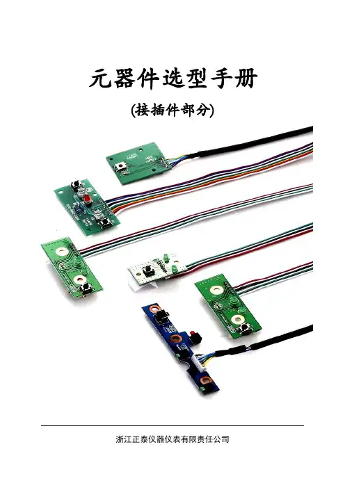
元器件选型手册(接插件部分)浙江正泰仪器仪表有限责任公司目录前言 (2)一、普通单双排插针 (3)二、普通单双排插座 (4)三、其他插针插座 (5)3.1蜈蚣插座 (5)3.2圆孔插座 (5)3.3DIP芯片插座 (6)3.4弯针 (6)四、线对板连接器 (7)4.1单排针座连接器 (7)4.2简牛针座 (9)4.3牛角针座 (9)五、USB接口 (10)六、天线及连接线 (11)七、其他类型接插件 (12)7.1FPC连接器 (12)7.2凤凰端子 (13)7.3PS2插座 (13)7.4DF12系列连接器 (13)7.5RJ45模块化插孔 (14)7.6IC卡座 (14)7.7SIM卡座 (14)前言1.范围本手册对公司目前使用的接插件进行了分类,对接插件的描述进行了定义。
本手册仅用于公司产品设计选型时参考。
2.注意事项本手册中部分物料因在规定的字符条件下无法描述清楚,故采用出图纸的方式,使用时,可以在PLM系统上直接查看或者下载。
本手册中物料描述的尺寸均未标明公差,如实际使用时对尺寸要求很高,请联系厂家出具规格承认书,或者参考GB/T 1804-2000。
所有物料的SAP描述均不能超过40个字符(包括空格)。
一、普通单双排插针1.1SAP描述规范双排单塑插针 2.54mm,2*14P,隔两排抽两排,针长16.5,深圳联颖①名称②脚间距③引脚数④(类型)⑤针尺寸⑥品牌①名称:单排单塑插针、双排单塑插针、单排双塑插针、双排双塑插针;②脚间距:一般为2.54mm或2mm;③引脚数:排数*单排引脚数;④(类型):如抽针,个别针加长等情况的说明,无特殊的可不写;⑤针尺寸:针长表示针两头之间的长度。
若PC=3mm默认不写,此时单塑插针,只需要写出针长;双塑插针,则需要写明针长和PA面长度;a1.2典型示例a PC面为针插入PCB的一端,PA面为远离PCB的一端。
二、普通单双排插座2.1 SAP描述规范双排插座 2.54mm,2*14P,隔两排抽两排,塑高8.5,深圳联颖①名称②脚间距③引脚数④(类型)⑤塑高⑥品牌①名称:双排插座、单排插座;②脚间距:一般为2.54mm或2mm;③引脚数:排数*单排引脚数;④(类型):如抽针等情况的说明,无特殊的可不写;⑤塑高:塑高表示焊接后的插座高度,也就是塑壳高度。
元器件选型手册

元器件选型手册(接插件部分)浙江正泰仪器仪表有限责任公司目录、/一前言 .......................................一、普通单双排插针 ..................................二、普通单双排插座 ..................................三、其他插针插座 ....................................蜈蚣插座. ............................................................圆孔插座. ............................................................DIP 芯片插座 ....................................弯针. ...............................................................四、线对板连接器 ....................................单排针座连接器. ........................................................简牛针座. ............................................................牛角针座. ............................................................五、USB接口....................................六、天线及连接线....................................七、其他类型接插件..................................FPC连接器....................................凤凰端子. ............................................................PS2插座......................................DF12系列连接器..................................RJ45 模块化插孔.................................IC 卡座.......................................SIM 卡座..................................... 错误!未定义书签错误!未定义书签错误!未定义书签错误!未定义书签错误!未定义书签错误!未定义书签错误!未定义书签错误!未定义书签错误!未定义书签错误!未定义书签错误!未定义书签错误!未定义书签错误!未定义书签错误!未定义书签错误!未定义书签错误!未定义书签错误!未定义书签错误!未定义书签错误!未定义书签错误!未定义书签错误!未定义书签错误!未定义书签刖言1. 范围本手册对公司目前使用的接插件进行了分类,对接插件的描述进行了定义。
(整理)电子元器件扫盲手册
电子元器件基础知识(1)——电阻导电体对电流的阻碍作用称为电阻,用符号R表示,单位为欧姆、千欧、兆欧,分别用Ω、KΩ、MΩ表示。
一、电阻的型号命名方法:国产电阻器的型号由四部分组成(不适用敏感电阻)第一部分:主称,用字母表示,表示产品的名字。
如R表示电阻,W表示电位器。
第二部分:材料,用字母表示,表示电阻体用什么材料组成,T-碳膜、H-合成碳膜、S-有机实心、N-无机实心、J-金属膜、Y-氮化膜、C-沉积膜、I-玻璃釉膜、X-线绕。
第三部分:分类,一般用数字表示,个别类型用字母表示,表示产品属于什么类型。
1-普通、2-普通、3-超高频、4-高阻、5-高温、6-精密、7-精密、8-高压、9-特殊、G-高功率、T-可调。
第四部分:序号,用数字表示,表示同类产品中不同品种,以区分产品的外型尺寸和性能指标等例如:R T 1 1 型普通碳膜电阻二、电阻器的分类1、线绕电阻器:通用线绕电阻器、精密线绕电阻器、大功率线绕电阻器、高频线绕电阻器。
2、薄膜电阻器:碳膜电阻器、合成碳膜电阻器、金属膜电阻器、金属氧化膜电阻器、化学沉积膜电阻器、玻璃釉膜电阻器、金属氮化膜电阻器。
3、实心电阻器:无机合成实心碳质电阻器、有机合成实心碳质电阻器。
4、敏感电阻器:压敏电阻器、热敏电阻器、光敏电阻器、力敏电阻器、气敏电阻器、湿敏电阻器。
三、主要特性参数1、标称阻值:电阻器上面所标示的阻值。
2、允许误差:标称阻值与实际阻值的差值跟标称阻值之比的百分数称阻值偏差,它表示电阻器的精度。
允许误差与精度等级对应关系如下:±0.5%-0.05、±1%-0.1(或00)、±2%-0.2(或0)、±5%-Ⅰ级、±10%-Ⅱ级、±20%-Ⅲ级3、额定功率:在正常的大气压力90-106.6KPa及环境温度为-55℃~+70℃的条件下,电阻器长期工作所允许耗散的最大功率。
线绕电阻器额定功率系列为(W):1/20、1/8、1/4、1/2、1、2、4、8、10、16、25、40、50、75、100、150、250、500非线绕电阻器额定功率系列为(W):1/20、1/8、1/4、1/2、1、2、5、10、25、50、1004、额定电压:由阻值和额定功率换算出的电压。
最新元器件选型手册接插件部分-1
元器件选型手册接插件部分-1元器件选型手册(接插件部分)浙江正泰仪器仪表有限责任公司目录前言 (2)1.范围 (2)2.注意事项 (2)一、普通单双排插针 (3)二、普通单双排插座 (4)三、其他插针插座 (5)3.1蜈蚣插座 (5)3.2圆孔插座 (5)3.3DIP芯片插座 (6)3.4弯针 (6)四、线对板连接器 (7)4.1单排针座连接器 (7)4.2简牛针座 (10)4.3牛角针座 (10)五、USB接口 (11)六、天线及连接线 (12)七、其他类型接插件 (13)7.1FPC连接器 (13)7.2凤凰端子 (14)7.3PS2插座 (14)7.4DF12系列连接器 (14)7.5RJ45模块化插孔 (15)7.6IC卡座 (15)7.7SIM卡座 (15)前言1.范围本手册对公司目前使用的接插件进行了分类,对接插件的描述进行了定义。
本手册仅用于公司产品设计选型时参考。
2.注意事项➢本手册中部分物料因在规定的字符条件下无法描述清楚,故采用出图纸的方式,使用时,可以在PLM系统上直接查看或者下载。
➢本手册中物料描述的尺寸均未标明公差,如实际使用时对尺寸要求很高,请联系厂家出具规格承认书,或者参考GB/T 1804-2000。
➢所有物料的SAP描述均不能超过40个字符(包括空格)。
一、普通单双排插针1.1SAP描述规范双排单塑插针 2.54mm,2*14P,隔两排抽两排,针长16.5,深圳联颖①名称②脚间距③引脚数④(类型)⑤针尺寸⑥品牌①名称:单排单塑插针、双排单塑插针、单排双塑插针、双排双塑插针;②脚间距:一般为2.54mm或2mm;③引脚数:排数*单排引脚数;④(类型):如抽针,个别针加长等情况的说明,无特殊的可不写;⑤针尺寸:针长表示针两头之间的长度。
若PC=3mm默认不写,此时单塑插针,只需要写出针长;双塑插针,则需要写明针长和PA面长度;a1.2典型示例描述单排单塑插针 2.54mm,1*17P,PC=5,针长11.5,尤提乐对照图描述双排单塑插针 2.54mm,2*16P,针长18,尤提乐对照图描述单排双塑插针 2.54mm,1*4P,针长15.5,PA=PC=3,深圳联颖对照图描述双排双塑插针 2.54mm,2*15P,针长27,PA=9,尤提乐a PC面为针插入PCB的一端,PA面为远离PCB的一端。
电子元件手册
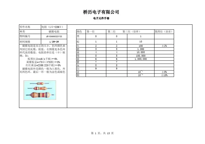
零件名称电阻(1Ω-22MΩ)种类碳膜电阻颜色第一位第二位第三位(倍率)第四位(误差)物料编号1R-C0000XXX-XX黑材料规格1/8W-3W棕 碳膜电阻是从它的大小,色环颜色来红判別它的瓦数,阻值。
右图便是各色环橙所代表的数值。
电阻的单位是(Ω)欧黄姆,如:绿蓝紫灰 碳膜电阻外壳颜色一般为土黄色,外白有四色环,最后一环一般为金色或银色金银红红黄金=220K(220千欧)+-5%110±2%0101±5%±10%10¯¹10¯²923100231,0008894410,00055电子元件手冊100,00077661,000,000棕黑红金=1K(1千欧)+-5% 黄紫棕金=470Ω(470欧)+-5%零件名称电阻(1Ω-22MΩ)种类金属膜电阻颜色物料编号1R-C000XXXX-XX 黑材料规格1/8W-5W棕 金属膜电阻外壳为蓝色,有五个色环红,右图是各色环所代表的意义。
橙如:黄绿蓝紫灰白金银下图是电阻体积与功率的关系:1/8W 1.7±0.50.45±0.051/4W 2.3±0.50.5±0.051/2W 3.0±0.50.6±0.051W 4.0±0.50.75±0.052.0W 5.0±0.50.75±0.053.0W8.0±0.50.75±0.05棕黑黑棕棕=1K(1千欧)+-1%红红黑橙棕=220K(220千欧)+-1%电子元件手冊9924±222±28881110¯²第一位第二位第三位第四位(倍率)10¯¹100第五位(误差)10±1%0001110,000±2%3331,000222555100,000±0.5%44491,000,0007776663.2±0.528±237±26.0±0.59.0±0.511±1.015±1.024±1.027±225±2类型H 电阻体(mm)引脚(mm)dL D零件名称电阻(1Ω-22MΩ)种类贴片电阻物料编号1R-C000XXXX-XX 材料规格贴片电阻,它以数字的形式标在电阻表面,换算方法和色环电阻一样依体积大小分为:0402,0603,0805,1206。
电子行业电子元件手册
电子行业电子元件手册第一章:导言随着科技的不断发展和进步,电子行业已经成为现代社会中不可或缺的一部分。
电子元件作为电子产品的基础构成部分,其种类繁多、功能各异。
本手册旨在为电子行业从业人员提供全面的电子元件知识,帮助他们更好地理解和应用电子元件。
第二章:电子元件分类2.1 有源元件有源元件是指能够放大电流或电压的元件,常见的有晶体管、集成电路等。
本节将介绍有源元件的基本原理、分类和特点。
2.2 无源元件无源元件是指不能放大电流或电压的元件,常见的有电阻、电容、电感等。
本节将介绍无源元件的基本原理、分类和特点。
第三章:常用电子元件3.1 电阻电阻是电子电路中最基本的元件之一,用于限制电流的流动。
本节将介绍电阻的种类、参数和应用。
3.2 电容电容是储存电荷的元件,常用于电源滤波、信号耦合等电路中。
本节将介绍电容的种类、参数和应用。
3.3 电感电感是储存磁场能量的元件,常用于滤波、变压器等电路中。
本节将介绍电感的种类、参数和应用。
3.4 二极管二极管是一种具有单向导电性的元件,常用于整流、开关等电路中。
本节将介绍二极管的种类、参数和应用。
3.5 晶体管晶体管是一种半导体器件,常用于放大、开关等电路中。
本节将介绍晶体管的种类、参数和应用。
3.6 集成电路集成电路是将多个电子元件集成在一块芯片上的元件,广泛应用于计算机、通信等领域。
本节将介绍集成电路的种类、参数和应用。
第四章:电子元件选型指南4.1 功能需求根据电路的功能需求来选择合适的电子元件,包括工作电压、工作频率等参数。
4.2 可靠性要求根据电路的可靠性要求来选择合适的电子元件,包括温度范围、寿命等参数。
4.3 成本考虑根据电路的成本考虑来选择合适的电子元件,包括单价、可替代性等因素。
第五章:电子元件应用案例5.1 电源电路介绍电子元件在电源电路中的应用案例,包括稳压电路、开关电源等。
5.2 信号处理电路介绍电子元件在信号处理电路中的应用案例,包括滤波电路、放大电路等。
元器件opa227器件使用手册
FEATURES
DESCRIPTION
q LOW NOISE: 3nV/√Hz q WIDE BANDWIDTH:
OPA227: 8MHz, 2.3V/µs OPA228: 33MHz, 10V/µs q SETTLING TIME: 5µs (significant improvement over OP-27) q HIGH CMRR: 138dB q HIGH OPEN-LOOP GAIN: 160dB q LOW INPUT BIAS CURRENT: 10nA max q LOW OFFSET VOLTAGE: 75µV max q WIDE SUPPLY RANGE: ±2.5V to ±18V q OPA227 REPLACES OP-27, LT1007, MAX427 q OPA228 REPLACES OP-37, LT1037, MAX437 q SINGLE, DUAL, AND QUAD VERSIONS
OPA227PA, UA OPA2227PA, UA OPA4227PA, UA
MIN
TYP
MAX
±10
±200
±200
±0.3
±2
✻
✻
✻
✻
✻
✻
✻
✻
✻
✻
✻
✻
✻ ✻ ✻ ✻ ✻ ✻
✻
✻
✻
✻
✻
✻ ✻
✻
✻
✻
✻
✻
✻
✻ ✻ ✻ ✻ ✻ ✻
✻
✻
✻
✻
✻
✻
✻
✻
✻
✻
✻
✻
✻
✻
✻
✻
✻
✻
西门子 低压电器元器件 快速选型手册
540
540
x 470 x 330 x 470 x 330
94
98
118
122
57
59
118
122
20 20 10 2 前、后 • • WxHxD 420 x 485 x 430 540 x 485 x 430 420 x 470 x 330 540 x 470 x 330 100 124 61 124
1000 ~ 2500A
3200A
1280 ~ 3200A
附件说明: • 未加说明时: 1. 带电气合闸线圈: AC 220V/ DC 220V 2. 带储能电机: AC 220V/ DC 220V 3. 辅助触头: 2 常开 + 2 常闭 4. 无分励脱扣器,无欠压脱扣器
• 附件变动时: 1. 储能电机、电气合闸线圈须注明电压类别、电压等级 2. 分励、欠压脱扣器须注明电压类别、电压等级 3. 辅助触头的数量 4. 机械联锁 5. 通讯功能、能量管理 6. 计数器、位置信号触头等其它附件 (请参见样本或咨询)
58
61
61
76
79
79
34
36
36
76
79
79
所有附件相同
20
20
20
20
10
10
2
2
前、后
前、后
•
•
•
•
WxHxD WxHxD
420
420
x 485 x 430 x 485 x 430
540
540
x 485 x 430 x 485 x 430
420
420
x 470 x 330 x 470 x 330
电子元器件产品说明书
Page Circuit protectionOvercurrent . . . . . . . . . . . . . . . . . . . . . . . . . . . . . . . . . .2 Overvoltage . . . . . . . . . . . . . . . . . . . . . . . . . . . . . . . . . .2 Terminal blocks . . . . . . . . . . . . . . . . . . . . . . . . . . . . . . .2Magnetics . . . . . . . . . . . . . . . . . . . . . . . . . . . . . . . . . . . . . . . .3Supercapacitors . . . . . . . . . . . . . . . . . . . . . . . . . . . . . . . . . . .4Miscellaneous . . . . . . . . . . . . . . . . . . . . . . . . . . . . . . . . . . . .5Circuit Protection- OvercurrentWhat is the termination finish and terminal material?Please contact technical support click here.What is the MSL level?Please contact technical support click here.Do you have 3D models (.STEP)?Please contact technical support click here for availability.What is the FIT/MTBF rate?There is no FIT/MTBF data for fuses. When an overcurrent event occurs, the fuse opens as designed and interrupts the flow of current. This is not a “fuse failure,” but a proper function of the fuse design. What are perceived as fuse and/or fuse holder “failures” are mostly reactions to excess heat produced by loose or corroded connections, improper component sizing or application outside the device’s operating temperature range. These are not device failures, but rather inappropriate device selection. Fuses do not require maintenance until an overcurrent event causes them to open – then they need replacing after properly addressing the cause of the overcurrent event.Do you have a cross for…..?Please visit our on-line cross reference search click here or contact technical support click hereHow do I select a fuse?Please visit our parametric search click here or contact technical support click here.Can fuses with an AC voltage rating be used in a DC voltage application?Fuses should be rated for the voltage AC or DC in which they will be used. The data sheet will usually have both an AC and DC voltage rating if they are recommended for both types of applications.Do fuses need to be derated to account for the operating temperature?Y es. Please contact technical support click here if the temperature derating information is not on the data sheet.What is the difference between interrupting rating (breaking capacity) and the fuse’s ampere rating?The breaking capacity or interrupting rating for a protective deviceis the maximum available current, at rated voltage, that the device can safely open. The ampere rating is the normal current the fuse is designed to carry at +25 °C. It is recommended, however, that the fuse’s current rating be at least 125 percent of the nominal operating current passing through the fuse. Both ratings are determined through testing.My circuit is “x” amperes. What amperage fuse should I select? The normal operating current of a circuit is the level of current drawn (in RMS or DC amperes) after it has been energized and is operating under normal conditions. An operating current of 80 percent or less of rated current is recommended for operation at+25 °C to avoid nuisance openings. For example, a fuse with a current rating of 1 A is usually not recommended in circuits with normal operating currents of more than 800 mA. Further derating is required at elevated ambient temperatures.Do fuse holders need derating?Y es. Generally this derating factor is in line with fuse derating of 80 percent but could be more depending on additional environmental or operating factors such as temperature and/or current cycling. Can a time delay fuse be used to replace a fast acting fuse?Fast acting fuses are typically used to protect sensitive components from damage. Time delay fuses are typically used in circuits that may have periodic spikes in current to avoid nuisance openings. Replacing fast acting fuses with a time delay fuse could result in damage to equipment.What clip, block, or holder is available for xxx fuse?Please see our Fuse accessory guide click here or contact technical support click here.Can ferrule fuses be soldered?Typically we do not recommend soldering of ferrule fuses. Please contact technical support click here for further questions.Circuit Protection- OvervoltageWhat is the termination finish and terminal material?Please contact technical support click here.What is the MSL level?Please contact technical support click here.Do you have a cross for…..?Please visit our on-line cross reference search click here or contact technical support click hereHow do I select an ESD suppressor?Please visit our parametric search parametric search click here or contact technical support click here.Do you have MOV and high voltage TVS?No. Currently our overvoltage product lines are low voltage ESD only devices.Can the ESD suppressor be wave soldered?Y es. Soldering profiles are typically listed on the data sheets. If there are questions please contact technical support click hereCircuit Protection- T erminal blocksDo you have a cross for…..?Please visit our on-line cross reference search click here or contact technical support click here.How do I select a terminal block?Please visit our parametric search click here or contact technical support click here.What is the MSL level?MSL is only applicable to surface mount devices. We do not currently offer any surface mount terminal block.2EATON /electronicsMagneticsWhat is the operating temperature range?It is the minimum and maximum range of ambient temperatures that a component can be safely operated. The maximumoperating temperature is defined as the magnetics device internal self temperature rise plus the maximum application ambient temperature exposed to the magnetics.The minimum operating temperature is defined as the absolute minimum application ambient temperature exposed to the magnetics. See Magnetics operating temperature defined application note click here for more detail.Can the inductor be run at higher current levels than the Irms rating?Y es. As long as the peak current rating is not exceeded and the device surface temperature is limited to its maximum rating.Why is the Irms rating higher than the Isat rating?The ratings for Irms and Isat are an indication of the inductor performance, in practice the inductor should not be used beyond its Isat rating.On some product data sheets a maximum frequency of over1 MHz is shown but the Irms derating curve only goes up to a few hundred kHz, why?The maximum frequency shown is the frequency at which the inductance will start to roll off. The de-rating curve is limited by the information the core manufacture supplies, generally the inductors can be used beyond the highest de-rating frequency without any issues. For example the SD family has been used at up to 2 MHz (with relatively low applied V-µs, about 10-20 percent of the ratedV-µs).What is the termination finish and terminal material?Please contact technical support click here.What is the MSL level?Typically magnetics MSL=1. Please contact technical supportclick here for verification.Do you havd 3D models (.STEP)?Please contact technical support click here for availability.What is the Junction temperature?Theta JA, Theta JC, Rja and Rjb are terms applicable only to active devices, such as integrated circuits. Inductors do not contain semiconductor material junctions and so do not have the same potential failure modes. Theta JA and Theta JC are therefore not applicable to inductors.Are inductors polarity sensitive?Unlike capacitors or diodes, single winding inductors do not have a functional polarity and work equally in either direction, so polarityis not important in the vast majority of end-use circuits. On rare occasions, it has been reported that some inductors perform better when mounted in one particular orientation, due to interaction with nearby components or ground plane conductors. Any asymmetrical performance is very much a function of the application, especially board layout.Do you have 115/230 Vac 60 Hz transformers?No.Do you have UL, CSA, VDE recognized transformers and inductors? No.Do you have 10/100 Base-T transformers or modules?No.What is the inductor thermal resistance ?Thermal resistance is not typically specified for inductors because inductors are rated by current and not by power. Y ou can approximate the thermal resistance by dividing the temperature rise due to Irms current (e.g. 40 °C rise) by the DCR times the square of the Irms rating:Rth (in °C/W) = 40 °C ÷ (DCR × Irms^2) where DCR is in Ohms and Irms is in amps.What is the inductor power rating?Inductor power ratings are not specified because the more meaningful rating for inductors is the Rms current rating. Inductor Rms current ratings are derived by applying DC or low frequency AC current and measuring the temperature rise.What is the FIT/MTBF rate?Please contact technical support click here.I need -55 °C storage. Y our parts are listed at -40 °C—can I still use them?We do not believe storage temperature of -55 °C will be an issue. However, we have not tested these parts at -55 °C and do not have any data to confirm or deny this theory.How do I select an inductor?Please visit our parametric search click here or contact technical support click here.Do you have a cross for……?Please visit our on-line cross reference search click here or contact technical support click here.Do you perform ESD testing on your components?ESD testing is typically performed on active devices. Our magnetics products are passive devices and not typically susceptible to ESD damage so we do not usually test for ESD damage. We recommend customers perform their own application specific ESD testing if necessary. Please contact technical support click here if you have further questions.3EATON /electronicsSupercapacitorsWhat is the termination finish and terminal material?Please contact technical support click here.What is the MSL level?MSL is only applicable to surface mount devices. We do not currently offer any surface mount supercapacitors.Do you have 3D models (.STEP)?Please contact technical support click here for availability.How can I use a supercapacitor for higher voltage applications? Higher voltage is achieved by placing supercapacitors in seriesC = 1/(1/C1 + 1/C2)ESR = ESR1 + ESR2Do I need to balance supercapacitors if connected in series?All of our standard packs and modules have balancing built in. Single cell product will require balancing when connected in series.How can I achieve higher capacitance or higher power?Higher capacitance or higher power is achieved by connecting supercapacitors in parallelC = C1 + C2ESR = 1/(1/ESR1 + 1/ESR2)Do I need to balance supercapacitors if connected in parallel? No.Can I connect two packs in series to get higher voltage?Y es, but is not recommended.What happens if the supercapacitor voltage exceeds the rated operating or surge voltage or exposed to a negative voltage?In both cases, if the condition occurs briefly, then there will not be an issue. After long exposure (minutes) excessive voltage will lead to gas generation and leakage or rupture of the safety vent.What will happen if you reverse supercapacitors polarity?Eaton supercapacitors have symmetrical electrodes, meaning they are similar in composition. When a supercapacitor is first assembled, either electrode can be designated positive or negative.Once the supercapacitor is charged for the first time, the electrodes become polarized. Although supercapacitors can be shorted to zero volts - electrodes maintain a very small amount of charge. The longer they are held charged in one direction, the more polarized they become. If reversed charged after prolonged charging in one direction, will reduce supercapacitor life.What is the charging current?Maximum recommended charge current is:Charge Voltage ÷ (5 x ESR)This can be exceeded in applications where the charge/discharge duty cycle is low. ESR will limit the practical charge current, in applications where charging is frequent care should be taken not to exceed the maximum recommended temperature rise of 3 °C for small cells and 15 °C for large cells and modules. What is the discharge current?Repeated charge/discharge cycles can cause damage if the temperature of the capacitor exceeds the recommended limit. During discharge the voltage at the capacitor terminals will instantaneously drop by a voltage;= Discharge Current x ESRTotal voltage drop over duration of the discharge;= Discharge Current x (ESR + t/C)t = duration of discharge, C = capacitance.What is the FIT/MTBF rate for supercapacitors?The typical ‘failure’ mode of supercapacitors is a drop in capacitance over time then the MTBF will vary from application to application depending upon the amount of design margin.It also means that the device MTBF will vary depending on what arbitrary limit you set as being device failure and is voltage and temperature dependent. MTBF data misleading when compared to Arrhenius plots.What effect do high and low temperatures have on the superca-pacitor?At sub-zero temperatures the electrolyte will start to freeze resulting in increased ESR and reduced capacitance. The part will return to “normal” when the temperature is raised.Continued exposure to high ambient temperatures will dry out the electrolyte causing the ESR to increase and capacitance to fall, this condition is irreversible.How to clean circuit board with supercapacitors?Can the supercapacitors be washed?Avoid cleaning of circuit boards, however if the circuit board must be cleaned use static or ultrasonic immersion in a standard circuit board cleaning fluid for no more than 5 minutes and a maximum tempera-ture of +60 °C. Afterwards thoroughly rinse and dry the circuit boards. In general, treat supercapacitors in the same manner you would an aluminum electrolytic capacitorWhat type of soldering can be used with supercapacitors? Through-hole supercapacitors should be wave soldered or manually soldered. Do not use reflow soldering. See Supercapacitor soldering gudeline application note click here for more details or contact technical support click hereHow do I select or size a supercapacitor?To select or size a supercapacitor vist or supercapacitor on-line calculator click here or our parametric search click here or contact technical support click here.Do you have a cross for…..?Please visit our on-line cross reference search click here or contact technical support click here.4EATON /electronicsEatonElectronics Division1000 Eaton Boulevard Cleveland, OH 44122 United States/electronics© 2019 EatonAll Rights ReservedPrinted in USAPublication No. 10854 BU-MC18077 January 2019 Eaton is a registered trademark. All other trademarks are property of their respective owners.MiscellaneousCan you provide a REACH certificate stating the REACH status Please see our REACH statement click here for contact information. Are your part RoHS compliant?Can you provide a RoHS certificate?Please visit the on-line search to retrieve RoHS certificates. Any exceptions will be listed on the certiifcate click here. If there are still questions please contact technical support click here.Can you please provide Conflict Mineral information?Please direct conflict mineral inquiries to ConflictMaterials@Eaton. com.Can you please provide ECCN, country of origin, HS code, cage code?Please direct all trade compliance inquiries to********************************Do you have qualification testing information?Y es. please contact technical support click here.What is Fit Form and Function?We define fit, form and function as follows:Fit – the ability of a part to physically interface with, connect to, or become an integral part of another part (i.e footprint)Form – the shape, size, dimensions, mass, weight and other visual parameters that uniquely distinguish a part.Function – the action or actions that a part is designed to perform (i.e electrical characteristics, performance curves)。
- 1、下载文档前请自行甄别文档内容的完整性,平台不提供额外的编辑、内容补充、找答案等附加服务。
- 2、"仅部分预览"的文档,不可在线预览部分如存在完整性等问题,可反馈申请退款(可完整预览的文档不适用该条件!)。
- 3、如文档侵犯您的权益,请联系客服反馈,我们会尽快为您处理(人工客服工作时间:9:00-18:30)。
元器件手册
附:常用元器件的识别
一、电阻
电阻在电路中用“R”加数字表示,如:R1表示编号为1的电阻。
电阻在电路中的主要作用为:分流、限流、分压、偏置等。
1、参数识别:电阻的单位为欧姆(Ω),倍率单位有:千欧(KΩ),兆欧(M Ω)等。
换算方法是:1兆欧=1000千欧=1000000欧
电阻的参数标注方法有3种,即直标法、色标法和数标法。
a、数标法主要用于贴片等小体积的电路,如:
472 表示 47×100Ω(即4.7K); 104则表示100K
b、色环标注法使用最多,现举例如下:
四色环电阻五色环电阻(精密电阻)
2、电阻的色标位置和倍率关系如下表所示:
颜色有效数字倍率允许偏差(%)
银色 / x0.01 ±10
金色/ x0.1 ±5
黑色 0 +0 /
棕色 1 x10 ±1
红色 2 x100 ±2
橙色 3 x1000 /
黄色 4 x10000 /
绿色 5 x100000 ±0.5
蓝色 6 x1000000 ±0.2
紫色 7 x10000000 ±0.1
灰色 8 x100000000 /
白色 9 x1000000000 /
二、电容
1、电容在电路中一般用“C”加数字表示(如C13表示编号为13的电容)。
电容是由两片金属膜紧靠,中间用绝缘材料隔开而组成的元件。
电容的特性主要是隔直流通交流。
电容容量的大小就是表示能贮存电能的大小,电容对交流信号的阻碍作用称为容抗,它与交流信号的频率和电容量有关。
容抗XC=1/2πf c (f表示交流信号的频率,C表示电容容量)
电话机中常用电容的种类有电解电容、瓷片电容、贴片电容、独石电容、钽电容和涤纶电容等。
2、识别方法:电容的识别方法与电阻的识别方法基本相同,分直标法、色标法和数标法3种。
电容的基本单位用法拉(F)表示,其它单位还有:毫法(mF)、微法(uF)、纳法(nF)、皮法(pF)。
其中:1法拉=103毫法=106微法=109纳法=1012皮法
容量大的电容其容量值在电容上直接标明,如10 uF/16V
容量小的电容其容量值在电容上用字母表示或数字表示
字母表示法:1m=1000 uF 1P2=1.2PF 1n=1000PF
数字表示法:一般用三位数字表示容量大小,前两位表示有效数字,第三位数字是倍率。
如:102表示10×102PF=1000PF 224表示22×104PF=0.22 uF
3、电容容量误差表
如:一瓷片电容为104J表示容量为0. 1 uF、误差为±5%。
三、晶体二极管
晶体二极管在电路中常用“D”加数字表示,如: D5表示编号为5的二极管。
1、作用:二极管的主要特性是单向导电性,也就是在正向电压的作用下,导通电阻很小;而在反向电压作用下导通电阻极大或无穷大。
正因为二极管具有上述特性,无绳电话机中常把它用在整流、隔离、稳压、极性保护、编码控制、调频调制和静噪等电路中。
电话机里使用的晶体二极管按作用可分为:整流二极管(如1N4004)、隔离二极管(如1N4148)、肖特基二极管(如BAT85)、发光二极管、稳压二极管等。
2、识别方法:二极管的识别很简单,小功率二极管的N极(负极),在二极管外表大多采用一种色圈标出来,有些二极管也用二极管专用符号来表示P极(正极)或N极(负极),也有采用符号标志为“P”、“N”来确定二极管极性的。
发光二极管的正负极可从引脚长短来识别,长脚为正,短脚为负。
3、测试注意事项:用数字式万用表去测二极管时,红表笔接二极管的正极,黑表笔接二极管的负极,此时测得的阻值才是二极管的正向导通阻值,这与指针式万用表的表笔接法刚好相反。
4、常用的1N4000系列二极管耐压比较如下:
四、稳压二极管
稳压二极管在电路中常用“ZD”加数字表示,如:ZD5表示编号为5的稳压管。
1、稳压二极管的稳压原理:稳压二极管的特点就是击穿后,其两端的电压基本保持不变。
这样,当把稳压管接入电路以后,若由于电源电压发生波动,或其它原因造成电路中各点电压变动时,负载两端的电压将基本保持不变。
2、故障特点:稳压二极管的故障主要表现在开路、短路和稳压值不稳定。
在这
3种故障中,前一种故障表现出电源电压升高;后2种故障表现为电源电压变低到零伏或输出不稳定。
常用稳压二极管的型号及稳压值如下表:
五、电感
电感在电路中常用“L”加数字表示,如:L6表示编号为6的电感。
电感线圈是将绝缘的导线在绝缘的骨架上绕一定的圈数制成。
直流可通过线圈,直流电阻就是导线本身的电阻,压降很小;当交流信号通过线圈时,线圈两端将会产生自感电动势,自感电动势的方向与外加电压的方向相反,阻碍交流的通过,所以电感的特性是通直流阻交流,频率越高,线圈阻抗越大。
电感在电路中可与电容组成振荡电路。
电感一般有直标法和色标法,色标法与电阻类似。
如:棕、黑、金、金表示1uH (误差5%)的电感。
电感的基本单位为:亨(H)换算单位有:1H=103mH=106uH。
六、变容二极管
变容二极管是根据普通二极管内部“PN结”的结电容能随外加反向电压的变化而变化这一原理专门设计出来的一种特殊二极管。
变容二极管在无绳电话机中主要用在手机或座机的高频调制电路上,实现低频信号调制到高频信号上,并发射出去。
在工作状态,变容二极管调制电压一般加到负极上,使变容二极管的内部结电容容量随调制电压的变化而变化。
变容二极管发生故障,主要表现为漏电或性能变差:
(1)发生漏电现象时,高频调制电路将不工作或调制性能变差。
(2)变容性能变差时,高频调制电路的工作不稳定,使调制后的高频信号发送到对方被对方接收后产生失真。
出现上述情况之一时,就应该更换同型号的变容二极管。
七、晶体三极管
晶体三极管在电路中常用“Q”加数字表示,如:Q17表示编号为17的三极管。
1、特点:晶体三极管(简称三极管)是内部含有2个PN结,并且具有放大能力的特殊器件。
它分NPN型和PNP型两种类型,这两种类型的三极管从工作特性上可互相弥补,所谓OTL电路中的对管就是由PNP型和NPN型配对使用。
电话机中常用的PNP型三极管有:A92、9015等型号;NPN型三极管有:A42、9014、9018、9013、9012等型号。
2、晶体三极管主要用于放大电路中起放大作用,在常见电路中有三种接法。
为了便于比较,将晶体管三种接法电路所具有的特点列于下表,供大家参考。
八、场效应晶体管放大器
1、场效应晶体管具有较高输入阻抗和低噪声等优点,因而也被广泛应用于各种电子设备中。
尤其用场效管做整个电子设备的输入级,可以获得一般晶体管很难达到的性能。
2、场效应管分成结型和绝缘栅型两大类,其控制原理都是一样的。
如图1-1-1是两种型号的表示符号:
3、场效应管与晶体管的比较
(1)场效应管是电压控制元件,而晶体管是电流控制元件。
在只允许从信号源取较少电流的情况下,应选用场效应管;而在信号电压较低,又允许从信号源取较多电流的条件下,应选用晶体管。
(2)场效应管是利用多数载流子导电,所以称之为单极型器件,而晶体管是即有多数载流子,也利用少数载流子导电。
被称之为双极型器件。
(3)有些场效应管的源极和漏极可以互换使用,栅压也可正可负,灵活性比晶体管好。
(4)场效应管能在很小电流和很低电压的条件下工作,而且它的制造工艺可以很方便地把很多场效应管集成在一块硅片上,因此场效应管在大规模集成电路中得到了广泛的应用。