CPM1300安装手册
迅达APMMR现场安装手册

迅达A P M M R现场安装手册SANY标准化小组 #QS8QHH-HHGX8Q8-GNHHJ8-HHMHGN#安装缩略图摘要本手册提供了在亚太区范围内使用脚手架安装300P MMR主要安装步骤的详细说明。
本手册为保密文件,并仅供授权的培训人员使用。
目录1 安全建议 (4)概要 (4)使用符号 (4)2 先决条件 (5)产品概述 (5)安装步骤 (7)专用工具 (9)3 施工现场准备工作 (10)4 导轨安装 (15)准备工作 (15)导轨支架安装 (15)导轨安装 (21)导轨基座 (21)导轨安装 (22)连接板校正 (24)5 Varidor 30AP C2 厅门入口安装 (25)门框预安装 (27)地坎支架 (30)门框和机械横梁 (31)地坎和护脚板 (35)门板 (36)C2井道互锁装置 (40)门解锁装置 (41)安装门重锤 (42)防护罩 (44)6 PMS420无齿轮机组安装 (45)机组支架 (47)安装PMS420无齿轮机组 (48)*手动应急操作选配装置 (51)制动器调整和制动力测试 (57)*曳引钢丝绳悬挂装置安装 (58)*安装限速器 (62)7 *安装GGM2-AP对重 (71)先决条件 (71)*机械安装 (72)*缓冲器支撑 (72)*对重校正 (73)*安全钳(选配) (74)*导靴 (76)油杯(选配) (79)*对重块 (79)*补偿链悬挂装置 (80)地震传感器(选配) (81)*调整和最后检查 (82)对重防护屏 (83)*对重防护屏后置 (83)*对重防护屏侧置 (84)8 安装轿厢架FRS9-AP/FRM9-AP (87)安装轿厢架FRS9-AP (87)FRS9-AP安全钳和导靴选配件 (98)FRM9-AP安全钳和导靴选配件 (99)9 安装曳引绳 (100)处理钢丝绳 (100)安装钢丝绳 (101)钢丝绳绳头安装 (105)检查钢丝绳张紧度和绳的润滑 (109)限速器钢丝绳 (110)10 轿厢P9KD-AP(CM)安装 (117)轿厢安装步骤 (118)*安装轿厢装璜 (134)安装满载、超载开关 (143)轿厢平衡装置 (144)11 V30 AP轿门安装 (145)11.1 C2轿门 (145)11.1.1 轿门机驱动 (146)11.1.2 轿门板 (147)11.1.3 轿门刀 (149)安装光幕(MiniMax光幕LVH) (151)12 安装缓冲器 (157)13 安装补偿链 (159)补偿链导向装置 (159)4-滚轮导靴 (159)2-滚轮导靴 (162)补偿链 (165)14 安装MX-GC (170)先决条件 (170)材料范围 (171)控制柜 (172)井道信息 (174)井道信息IGSI (174)绝对值线型井道信息系统 (190)控制柜内模块 (210)机房电缆 (211)井道电缆 (215)准备 (220)安装 (223)调整和最后检查 (229)OKR (231)随行电缆 (236)带IGSI和LONCIB的MX-GC,HQ<=70m (237)带IGSI和LONCIB的MX-GC,HQ>70m (238)带IGSI和LONIC/LONICK的MX-GC,HQ<=70m (239)带IGSI和LONIC/LONICK的MX-GC,HQ>70m (240)控制柜内的概述与名称 (241)15 VARIODYN VF44BR和VF88BR安装 (243)VARIODYN VF44BR安装 (243)VARIODYN VF88BR安装 (249)1 安全建议概要安全要求所有参与的安装人员必须熟悉并遵守公司以及当地的安全规范,特别要注意以下几点:照明必须充足,以保证安全生产。
Cisco Aironet 1300系列出口无线接入点或桥说明书

Ordering GuideCisco Aironet 1300 Series Outdoor Access Point or BridgeThe Cisco® Aironet® 1300 Series Outdoor Access Point or Bridge is available with the following choices:●Operating autonomously or with a Cisco wireless LAN controller as part of a unified architecture●With a 13-dBi integrated antenna or with RP-TNC connectors for an externally attached antenna●For the FCC, ETSI, or TELEC regulatory domainsTwelve versions are available for different combinations of these options:●Cisco Aironet 1310 Outdoor Access Point/Bridge with 13-dBi integrated antenna, FCC config●Cisco Aironet 1310 Outdoor Access Point/Bridge with 13-dBi integrated antenna, ETSI config●Cisco Aironet 1310 Outdoor Access Point/Bridge with 13-dBi integrated antenna, TELEC config●Cisco Aironet 1310 Outdoor Access Point/Bridge with RP-TNC type Connectors, FCC config●Cisco Aironet 1310 Outdoor Access Point/Bridge with RP-TNC type Connectors, ETSI config●Cisco Aironet 1310 Outdoor Access Point/Bridge with RP-TNC type Connectors, TELEC config●Cisco Aironet 1310 LWAPP Outdoor Access Point with 13-dBi integrated antenna, FCC config●Cisco Aironet 1310 LWAPP Outdoor Access Point with 13-dBi integrated antenna, ETSI config●Cisco Aironet 1310 LWAPP Outdoor Access Point with 13-dBi integrated antenna, TELEC config●Cisco Aironet 1310 LWAPP Outdoor Access Point with RP-TNC type connectors, FCC config●Cisco Aironet 1310 LWAPP Outdoor Access Point with RP-TNC type connectors, ETSI config●Cisco Aironet 1310 LWAPP Outdoor Access Point with RP-TNC type connectors, TELEC configA Cisco Aironet 1300 Series device operating autonomously is an intelligent access point or bridge, capable of functioning as a standalone device. As an LWAPP access point, the Cisco Aironet 1300 Series works along with the Cisco wireless LAN controller to enable centralized configuration and management, application of security policies, and seamless mobility. When operating with wireless LAN controllers, Cisco Aironet 1300 Series Outdoor Access Points/Bridges function only as access points and are not capable of bridging.The integrated antenna versions feature a radio and high-gain patch antenna for user installations of either point-to-point links or non-root nodes of point-to-multipoint networks. The connectorized versions provide professional installers with RP-TNC type connectors that allow the deployment of nodes with omnidirectional, sector, or high-gain dish antennas for longer links. In all cases, the mounting kit must be ordered separately.All parts, along with accessories such as the Roof Mount Kit, Wall Mount Kit, cable, antennas, and power supplies, are available on the Cisco Systems® global and wholesale price lists.Cisco Aironet 1300 Series Outdoor Access Point or Bridge with 13-dBi Integrated AntennaThe Cisco Aironet 1300 Series Outdoor Access Point or Bridge features an 802.11g 2.4-GHz radio, which supports data rates up to 54 Mbps. With this option, a 13-dBi patch antenna is integrated into the ruggedized enclosure (Table 1).Table 1. Cisco Aironet 1300 Series Outdoor Access Point or Bridge with Integrated Antenna Product Number Product DescriptionAIR-BR1310G-A-K9 (FCC regulatory domain) AIR-BR1310G-E-K9 (EMEA regulatory domain) AIR-BR1310G-J-K9 (TELEC regulatory domain) ●Cisco Aironet 1300 Series Outdoor Access Point or Bridge with integrated patch antenna ●Cisco IOS® Software●Ships with:◦Power cord (configurable)◦100 to 240 VAC power supply (AIR-PWR-A=) providing 48 VDC to the power injector ◦48 VDC power injector (AIR-PWRINJ-BLR2=)◦1-ft dual RG-6 cable assembly (Ethernet uplink from power injector)●Roof Mount Kit available separately (AIR-ACCRMK1300=)●12 to 40 VDC power injector (AIR-PWRINJ-BLR2T=) for use with DC power supply installations available separatelyAIR-LAP1310G-A-K9 (FCC regulatory domain) AIR-LAP1310G-E-K9 (EMEA regulatory domain) AIR-LAP1310G-J-K9 (TELEC regulatory domain) ●Cisco Aironet 1300 Series Outdoor Access Point with integrated patch antenna●Cisco Lightweight Access Point Protocol●Ships with:◦Power cord (configurable)◦100 to 240 VAC power supply (AIR-PWR-A=) providing 48 VDC to the power injector ◦48 VDC power injector (AIR-PWRINJ-BLR2=)◦1-ft dual RG-6 cable assembly (Ethernet uplink from power injector)●Roof Mount Kit available separately (AIR-ACCRMK1300=)●12 to 40 VDC power Injector (AIR-PWRINJ-BLR2T=) for use with DC power supply installations available separatelyCisco Aironet 1300 Series Outdoor Access Point/Bridge with RP-TNC Type ConnectorsA connectorized version of the Cisco Aironet 1300 Series Outdoor Access Point or Bridge provides professional installers with RP-TNC type connectors that allow the deployment of nodes with omnidirectional, sector, or high-gain dish antennas for custom installations (Table 2).Table 2. Cisco Aironet 1300 Series Outdoor Access Point/Bridge with RP-TNC Type ConnectorsProduct Number Product DescriptionAIR-BR1310G-A-K9-R (FCC regulatory domain) AIR-BR1310G-E-K9-R (EMEA regulatory domain) AIR-BR1310G-J-K9-R (TELEC regulatory domain) ●Cisco Aironet 1300 Series Outdoor Access Point or Bridge with RP-TNC type connector ●Cisco IOS Software●Ships with:◦Power cord (configurable)◦100 to 240 VAC power supply (AIR-PWR-A=) providing 48 VDC to the power injector ◦48 VDC power injector (AIR-PWRINJ-BLR2=)◦1-ft dual RG-6 cable assembly (Ethernet uplink from power injector)●Roof Mount Kit (AIR-ACCRMK1300=) and Wall Mount Kit (AIR-ACCWAMK1300=) available separately●Optional 5-ft, 2.4-GHz RF jumper cable available separately●Antennas available separatelyAIR-LAP1310G-A-K9R (FCC regulatory domain) AIR-LAP1310G-E-K9R (EMEA regulatory domain) AIR-LAP1310G-J-K9R (TELEC regulatory domain) ●Cisco Aironet 1300 Series Outdoor Access Point with RP-TNC type connector●Cisco Lightweight Access Point Protocol●Ships with:◦Power cord (configurable)◦100 to 240 VAC power supply (AIR-PWR-A=) providing 48 VDC to the power injector ◦48 VDC power injector (AIR-PWRINJ-BLR2=)◦1-ft dual RG-6 cable assembly (Ethernet uplink from power injector)●Roof Mount Kit (AIR-ACCRMK1300=) and Wall Mount Kit (AIR-ACCWAMK1300=) available separately●Optional 5-ft, 2.4-GHz RF jumper cable available separately●Antennas available separatelyAIR_BR1310G-A-K9-T(FCC regulatory domain for Transportation) ●Ships with:◦12 to 40 VDC power injector (AIR-PWRINJ-BLR2T=) for use with DC power supply installations◦1-ft dual RG-6 cable assembly (Ethernet uplink from power injector)◦Threaded power connectorSoftware OptionsCisco Aironet 1300 Series devices can be ordered as an autonomous access point or bridge (AIR-BR1310G-x-K9 or AIR-BR1310G-x-K9 R). Alternatively, you can order an LWAPP-based version that works along with Cisco wireless LAN controllers (AIR-LAP1310G-x-K9 orAIR-LAP1310AG-x-K9R). When you order an autonomous Cisco Aironet 1300 Series device, you must select the software image as part of the configuration. When you order an LWAPP-based Cisco Aironet 1300 Series device, no software need be specified because this is managed by the controller.Mounting Kits for Cisco Aironet 1300 Series Outdoor Access Point/BridgesA Roof Mount Kit is available for use with the Cisco Aironet 1300 Series Outdoor Access Point or Bridge (integrated antenna and connectorized versions). A Wall Mount Kit is available for use with the Cisco Aironet 1300 Series Outdoor Access Point or Bridge with the RP-TNC type connector. The Wall Mount Kit is for indoor use only. These kits must be ordered separately (Table 3).Table 3. Mounting Kits for Cisco Aironet 1300 Series Outdoor Access Point or BridgeProduct Number Product DescriptionAIR-ACCWAMK1300= ●Cisco Aironet 1300 Series Wall Mount Kit for use with AIR-BR1310G-x-K9-R or AIR-LAP1310G-x-K9R●Kit includes:◦Wall-mount bracket◦Mounting hardware◦1-ft, dual RG-59 cable assembly (Ethernet uplink from power injector)AIR-ACCRMK1300= ●Cisco Aironet 1300 Series Roof Mount Kit for use with AIR-BR1310G-x-K9, AIR-BR1310G-x-K9-R, AIR-LAP1310G-x-K9, or AIR-LAP1310G-x-K9R●Kit includes:◦Roof-mount mast (pole and mounting base)◦Multifunction mount (allows mounting to roof-mount mast, or directly to a wall)◦Mounting hardware◦20-ft dual RG-6 cable assembly with F-Type connectors◦50-ft dual RG-6 cable assembly with F-Type connectors◦Coaxial sealant◦One Cisco Aironet grounding block◦Grounding lug◦Anticorrosion gel◦U-bolts◦Optional 100-ft dual RG-6 cable available separatelyAntennas for Cisco Aironet 1300 Series Outdoor Access Point or Bridge with RP-TNC Type ConnectorsThe Cisco Aironet 1300 Series Outdoor Access Point or Bridge with RP-TNC type connectors is certified to operate with the complete range of Cisco 2.4-GHz antennas listed in Table 4. Note that some high-gain antennas are applicable only for the Cisco Aironet 1300 Series operating as a bridge. Because of this, and because the LWAPP-based Cisco Aironet 1300 Series operates only as an access point, these antennas are not supported by Cisco wireless LAN controllers or in the Cisco Wireless Control Software (WCS). The antennas that are not supported by wireless LAN controllers or WCS are marked by an asterisk in Table 4.Antennas must be ordered separately.Table 4. Antennas for the Cisco Aironet 1300 Series Outdoor Access Point or Bridge with RP-TNC Type ConnectorProduct Number Product DescriptionAIR-ANT2414S-R* Cisco Aironet 2.4-GHz, 14-dBi sector antennaAIR-ANT2506 Cisco Aironet 2.4-GHz, 5.2-dBi omnidirectional mast-mount antennaAIR-ANT24120* Cisco Aironet 2.4-GHz, 12-dBi omnidirectional mast-mount antennaProduct Number Product DescriptionAIR-ANT1949* Cisco Aironet 2.4-GHz, 13.5-dBi Yagi antennaAIR-ANT2410Y-R Cisco Aironet 2.4-GHz , 10-dBi Yagi antennaAIR-ANT3338* Cisco Aironet 2.4-GHz, 21-dBi dish antennaAIR-ANT3549 Cisco Aironet 2.4-GHz, 9-dBi patch antenna* This antenna is not supported by the wireless LAN controllers or by WCSOptional Cables for Cisco Aironet 1300 Series Outdoor Access Point or Bridge Additional cables are available for use with 2.4-GHz antennas (Table 5).Table 5. Optional Cables for Cisco Aironet 1300 Series Outdoor Access Point or BridgeProduct Number Product DescriptionAIR-CAB005LL-R Cisco Aironet 5-ft, low-loss, 2.4-GHz RF cable with RP-TNC connectorsAIR-CAB020LL-R 20-ft low loss cable assembly with RP-TNC connectorsAIR-CAB050LL-R 50 ft low loss cable assembly with RP-TNC connectorsAIR-CAB100ULL-R 100 ft ultra low loss cable assembly with RP-TNC connectors。
PagePro 1300W 1350W 说明书

项卡。
10
显示打印机驱动程序设置
使用打印机驱动程序
" 有关所有这些功能的信息,请参阅打印机驱动程序的联机帮助。
通用按钮
下述按钮会出现在每个选项卡上。
2 依照屏幕说明进行操作。
" 对于 USB 连接,请选择“USBxxx”作为打印机端口。
对于并行连接,请选择“LPTx”作为打印机端口。
安装打印机驱动程序
7
8
安装打印机驱动程序
使用打印机驱动 程序
显示打印机驱动程序设置
在 Windows XP 下显示设置
1 从开始菜单中,选择控制面板。 2 在选一个类别中,单击打印机和其他硬件。 3 在选择一项任务 ... 中,单击查看安装的打印机或传真打印机。 4 在打印机和传真机目录中,选择 KONICA MINOLTA PagePro 1300W/
3 使用打印机驱动程序 ............................................................................................ 9 显示打印机驱动程序设置 10
目录
i
在 Windows XP 下显示设置 10 在 Windows 2000/Me/98 下显示设置 10 使用打印机驱动程序 11 通用按钮 11
的碳粉盒。
MINOLTA 碳
粉盒。
注意
如果使用非本地区适用、非认可或使用寿命已结束的碳粉盒,则每打印一页就 会进行清洁,这将降低打印速度。
4
关于指示灯功能
Alcatel 1300 CMC网管操作手册060913154849

输入登陆系统的用户名和密码。
我们现在对于一般操作员配置的登陆用户和密码为这时候窗口中有三个图标“Normal Desktop”, “Alcatel TMN OSs” and “X-网管系统管理点击桌面右下角的“Alcatel TMN OSs”图标打开网管系统管理窗口。
在窗口中的面板里显示有一个名为“CMC_1”的CMC1.0显示CMC系统的相关信息。
“Topology Manager”显示所有CMC管理的网元及其逻辑拓扑图,并用不同的颜色表示其告警状态。
1.0CMC的告警主面板,接收所有网元上传的即时告警,并能利用不同的过滤条件创建不同的子列表,方便告警的归类。
双击子列表名称可以进入告警子列表窗口。
1.0这时候,可以根据想要获取的历史告警信息创建相应的子列表,方法同告警子列表的创建。
选择窗口上菜单Archive -> Retrieve from Public Archive… -> CMC_1来获取历史告警。
在获取进度条消失后,可以到相应的子列表中查找需要的历史告警。
1.0操作员管理,可以在这里删创网管系统登陆用户,给用户配置对应的用户profile “Backup Management”对CMC网管系统已备份的数据进行恢复。
1.0NE Administration -> NE Attributes,显示所有已连接到网管的网元信息。
Network Operation -> Call Connection Trace,跟踪一个电话使用时所占用资源的所有信息。
1.01.01.0选择并填写好参数后,先点击TOF窗口中右上第二个按钮[Validate TOF Data]确认参数的正确性。
验证成功后,右上第一个按钮[Submission to NE]可用状态,点击就可将命令下发到网元,网元返回的报告会返回到程序MML Task Monitor中。
所以在执行“MML Menu Hierarchy”请确认程序“Monitor”已经打开。
科隆1300质量流量计安装调试手册(简)

科隆质量流量计手册(简易版)一、安装通常,对于OPTIMASS系列无需特殊的安装要求。
但是,还是应该遵守有关流量计安装的良好常规工程实践经验。
a 质量流量计通常不需要任何前后直管段。
b 由于仪表有重量,所以我们推荐使用支架,允许支撑仪表主体。
c 仪表可以水平安装,可以安装在向上倾斜的管道内或垂直安装。
为了获得最佳效果,推荐垂直安装,介质流动方向向上。
请注意:流经仪表后的长距离下降可能导致虹吸从而出现测量误差。
避免将仪表安装在管线中的最高点。
d 仪表的如下标签表示在功能C1.3.1中预设在转换器中的流体流动方向,默认情况下流向由“—”到“+”。
e 电源连接请注意:通电前,请确认仪表铭牌上的数据、电源电压和频率范围f 输出连接若仪表为电流输出时,请连接接线端子A+和A,其中端子A+为“+”端子A 为“—”,如下图:二、参数设置a 科隆质量流量计OPTIMASS1300系列流量见下表,可在菜单A4.3中设置输出范围。
为避免输出错误,量程最小值最好设置为0。
b 仪表有流量累积的功能,若第一个测量页面无累积流量显示可在菜C6.3.1选择两行显示,其单位可在C6.7.13中更改。
三、零点校准(菜单C1.1.1)装置完好性检查后,使用前必须在仪表上设置零点。
在零点设置前,必须先完成装置的所有改装/调节。
零点设置后对装置的任何改装或更改都将导致仪表性能不可靠,如发生这种情况,则需要重新设置零点。
如要完成正确无误的零点校准,必须注意以下几点:1、传感器中必须充满具有正常工作压力和工作温度的工艺流体;2、必须将流体中的空气全部除去,尤其对于水平安装。
建议在调节前先使用高流率(大于50%)的工艺流体冲洗传感器5分钟以上;3、冲洗后,必须完全关闭相应的阀门使传感器中的流量恢复为0(传感器中充满工艺流体但处于静止状态)。
阀门开关顺序:开启仪表旁路阀门→完全关闭仪表下游阀→完全关闭仪表上游阀门→菜单零点校准(见下表)→开启仪表上游阀门→开启仪表下游阀门→关闭仪表旁路阀门。
XMC1300 Boot Kit用户手册说明书
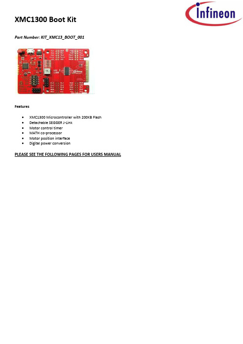
XMC1300 Boot KitPart Number: KIT_XMC13_BOOT_001Features∙XMC1300 Microcontroller with 200KB Flash∙Detachable SEGGER J-Link∙Motor control timer∙MATH co-processor∙Motor position interface∙Digital power conversionPLEASE SEE THE FOLLOWING PAGES FOR USERS MANUALXMC1300 CPU Card For XMC1000 FamilyCPU-13A-V1XMC1300 CPU CardBoard User's Manual Revision 2.0, 2013-12-18Edition 2013-12-18Published byInfineon Technologies AG81726 Munich, Germany© 2013 Infineon Technologies AGAll Rights Reserved.Legal DisclaimerThe information given in this document shall in no event be regarded as a guarantee of conditions or characteristics. With respect to any examples or hints given herein, any typical values stated herein and/or any information regarding the application of the device, Infineon Technologies hereby disclaims any and all warranties and liabilities of any kind, including without limitation, warranties of non-infringement of intellectual property rights of any third party.InformationFor further information on technology, delivery terms and conditions and prices, please contact the nearest Infineon Technologies Office ().WarningsDue to technical requirements, components may contain dangerous substances. For information on the types in question, please contact the nearest Infineon Technologies Office.Infineon Technologies components may be used in life-support devices or systems only with the express written approval of Infineon Technologies, if a failure of such components can reasonably be expected to cause the failure of that life-support device or system or to affect the safety or effectiveness of that device or system. Life support devices or systems are intended to be implanted in the human body or to support and/or maintain and sustain and/or protect human life. If they fail, it is reasonable to assume that the health of the user or otherTrademarks of Infineon Technologies AGAURIX™, C166™, CanPAK™, CIPOS™, CIPURSE™, EconoPACK™, CoolMOS™, CoolSET™, CORECONTROL™, CROSSAVE™, DAVE™, DI-POL™, EasyPIM™, EconoBRIDGE™, EconoDUAL™, EconoPIM™,EconoPACK™,EiceDRIVER™, eupec™, FCOS™, HITFET™, HybridPACK™, I²RF™, ISOFACE™, IsoPACK™, MIPAQ™, ModSTACK™,my-d™, NovalithIC™, OptiMOS™, ORIGA™, POWERCODE™, PRIMARION™, PrimePACK™, PrimeSTACK™, PRO-SIL™, PROFET™, RASIC™, ReverSave™, SatRIC™, SIEGET™, SINDRION™, SIPMOS™, SmartLEWIS™, SOLID FLASH™, TEMPFET™, thinQ!™, TRENCHSTOP™, TriCore™.Other TrademarksAdvance Design System™ (ADS) of Agilent Technologies, AMBA™, ARM™, MULTI-ICE™, KEIL™, PRIMECELL™, REALVIEW™, THUMB™, µVision™ of ARM Limited, UK. AUTOSAR™ is licensed by AUTOSAR development partnership. Bluetooth™ of Bluetooth SIG Inc. CAT-iq™ of D ECT Forum. COLOSSUS™, FirstGPS™ of Trimble Navigation Ltd. EMV™ of EMVCo, LLC (Visa Holdings Inc.). EPCOS™ of Epcos AG. FLEXGO™ of Microsoft Corporation. FlexRay™ is licensed by FlexRay Consortium. HYPERTERMINAL™ of Hilgraeve Incorporated. IEC™ of Commission Electrotechnique Internationale. IrDA™ of Infrared Data Association Corporation. ISO™ of INTERNATIONAL ORGANIZATION FOR STANDARDIZATION. MATLAB™ of MathWorks, Inc. MAXIM™ of Maxim Integrated Products, Inc. MICROTEC™, NUCLEUS™ of Mentor Graphics Corporation. MIPI™ of MIPI Alliance, Inc. MIPS™ of MIPS Technologies, Inc., USA. muRata™ of MURATA MANUFACTURING CO., MICROWAVE OFFICE™ (MWO) of Applied Wave Research Inc., OmniVision™ of OmniVision Technologies, Inc. Openwave™ Openwave Systems Inc. RED HAT™ Red Hat, Inc. RFMD™ RF Micro Devices, Inc. SIRIUS™ of Sirius Satellite Radio Inc. SOLARIS™ of Sun Microsystems, Inc. SPANSION™ of Spansion LLC Ltd. Symbian™ of Symbian Software Limited. TAIYO YUDEN™ of Taiyo Yuden Co. TEAKLITE™ of CEVA, Inc. TEKTRONIX™ of Tektr onix Inc. TOKO™ of TOKO KABUSHIKI KAISHA TA. UNIX™ of X/Open Company Limited. VERILOG™, PALLADIUM™ of Cadence Design Systems, Inc. VLYNQ™ of Texas Instruments Incorporated. VXWORKS™, WIND RIVER™ of WIND RIVER SYSTEMS, INC. ZETEX™ of Diodes Zetex Limited.Last Trademarks Update 2011-11-11Table of Contents1Overview (7)1.1Key Features (7)1.2Block Diagram (7)2Hardware Description (8)2.1Power Supply (8)2.2Reset (9)2.3Clock Generation (9)2.4Boot Option (9)2.5Debug Interface and virtual com port (9)2.6LED (9)2.7Potentiometer (10)2.8Application Card connector (10)3Production Data (12)3.1Schematics (12)3.2Layout and Geometry (15)3.3Bill of Material (15)List of FiguresFigure 1Block Diagram of XMC1300 CPU Card (7)Figure 2XMC1300 CPU Card (8)Figure 3Power Supply circuit (8)Figure 4LEDs circuit (10)Figure 5Potentiometer Circuit (10)Figure 6Pinout of the 2x30 pin edge connector (11)Figure 7Schematic 1 of 2 XMC1300 CPU Card (13)Figure 8Schematic 2 of 2 XMC1300 CPU Card (14)Figure 9XMC1300 CPU Card layout and geometry (15)List of TablesTable 1Debug connector X201 (9)Table 2LEDs Pinout (10)Table 3XMC1300 CPU Card (15)IntroductionThis document describes the features and hardware details of the XMC1300 CPU Card. This board is mounted with ARM® Cortex TM-M0 based XMC1300 Microcontroller from Infineon Technologies AG. This board is part of Infineon’s XMC1000 Application Kits1 OverviewThe XMC1300 CPU board (CPU-13A-V1) houses the XMC1300 Microcontroller and a 2x30 pin edge for application expansion. The board along with application cards (e.g. Colour LED Card, White LED Card) demonstrates the capabilities of XMC1300. The main use case for this board is to demonstrate the generic features of XMC1300 device including tool chain. The focus is safe operation under evaluation conditions. The board is neither cost nor size optimized and does not serve as a reference design.1.1 Key FeaturesThe XMC1300 CPU Card is equipped with the following features∙XMC1300 (ARM®Cortex TM-M0 based) Microcontroller, TSSOP38∙Connection to XMC1300 application cards via card edge connector∙Detachable J-Link debugger and UART virtual COM port, with micro USB connector∙Six user LEDs∙Potentiometer, connected to analog input P2.5∙Power supply via Micro-USB connector1.2 Block DiagramFigure 1 shows the functional block diagram of the XMC1300 CPU Card.Features include:−On board Debugger, for downloading and debugging of application code−Virtual com port for uart communication with terminal program e.g. Hyperterminal.−2x30 card edge connector, for extension to application card e.g. Colour LED Card and White LED Card.− 6 User LEDs connected to GPIO P0.0, P0.1, P0.6, P0.7, P0.8 and P0.9−Variable resistor R110 connected to Analog input P2.5−All the pins of XMC1300 are accessible via the connector JP101, JP102, JP103 and JP104Figure 1 Block Diagram of XMC1300 CPU Card2 Hardware DescriptionThe following sections give a detailed description of the hardware and how it can be used.Figure 2 XMC1300 CPU Card2.1 Power SupplyXMC1300 CPU Card is powered from the micro USB connector (5V); however, there is a current limit that can be drawn from the host PC through USB. If the CPU-13A-V1 board is used to drive other application board (e.g. Colour LED Card, White LED Card) and the total current required exceeds 500mA, then the board needs to be powered by external power supply connected to VDD and GND connection on board.The XMC1300 device can operate by power supply of 1.8V till 5.5Vdc. On this board, 5Vdc is used to power the XMC1300 device. However, if user wants to power the XMC1300 device with 3.3Vdc, then, set Jumper at JP201 to 3.3V side.Figure 3 Power Supply circuit2.2 ResetXMC1300 does not have a reset pin, hence, user can unplug and replug the USB cable to achieve power-on master reset.2.3 Clock GenerationNo external clock source is required. XMC1300 has two internal oscillators DCO1 and DCO2. DCO1 has a clock output of 64MHz. DCO2 is used to generate the standby clock running at 32.768KHz which used for Real Time Clock too. The main clock, MCLK and fast peripherial clock, PCLK, are generated from DCO1’s output.2.4 Boot OptionAfter power-on reset with master reset, XMC1300 device will enter different boot mode depend on the BMI (Boot Mode Index) value stored in XMC1300’s f lash configuration sector 0 (CS0). The BMI value pre-programmed on the XMC1300 device on CPU Card is User mode with debug enabled, hence, the XMC1300 device will start to run the application code in its embedded Flash after power on reset.2.5 Debug Interface and virtual com portXMC1300 CPU Card has on-board debugger which supports Serial Wire Debug (SWD) and Single Pin Debug (SPD) as debug interface. SPD is a proprietary debugging protocol from Infineon Technologies and it requires only 1 pin for debug communication. The debugger also provides a virtual COM port which support UART communication via P1.3 (rx-in) and P1.2 (tx-out) of XMC1300. There is a 2x5 pins Header Debug connector X201.Table 1 Debug connector X2012.6 LEDThe port pins P0.0, P0.1, P0.6, P0.7, P0.8 and P0.9 are connected to LED101, LED102, LED103, LED104, LED105 and LED106 respectively. The LED is turn on by output ‘L ow’ at the port pin.Figure 4 LEDs circuit2.7 PotentiometerXMC1300 CPU Card provides a potentiometer R110 for ease of use and testing of the on-chip analog to digital converter. The potentiometer is connected to the analog input P2.5. The analog output of the potentiometer is the same the VDDP voltage supplied to the XMC1300 device.Figure 5 Potentiometer Circuit2.8 Application Card connectorXMC1300 CPU Card has a 2x30 pins card edge connector. The mating connector is SAMTEC HSEC8-130-01-L-RA-XX.Figure 6 Pinout of the 2x30 pin edge connector3 Production Data3.1 SchematicsThis chapter contains the schematics for the XMC1300 CPU Card:∙Figure 7: CPU, Pin Headers, Potentiometer and LED and 60pin Edge connector ∙Figure 8: On-board Debugger, Power Supply3.2 Layout and GeometryFigure 9 XMC1300 CPU Card layout and geometry 3.3 Bill of Materialw w w.i n f i n e o n.c o m。
光端机安装使用手册

光端机说明书数字式视.音频及控制数据光端机目录1、概要 (2)2、一般安全要求 (2)3、应用场合 (2)4、数字光端机产品分类及产品说明 (3)5、数字光端机技术参数 (11)6、产品技术特点 (12)7、系统连接图 (13)8、安装步骤 (13)9、控制数据、音频信号端口及接口线定义 (15)10、简单故障检查分析与排除2111、 ..................................................................................................................... 附件22一、概要非常感谢您选用我公司生产的高可靠数字视音频及控制数据光传输系统!持续为用户提供优质产品和优质服务是我们的目标。
为确保您正确、安全地使用我们的产品,敬请您在使用前仔细阅读本手册,以减少或避免在安装和使用过程中可能遇到的问题。
视音频光端机因视频路数、音频路数、控制数据路数及其信号传输方向的不同,使光端机的型号繁多。
本手册中将同一基本配置衍生的系列产品归为一个产品组,同一产品组产品的使用及连接方法类同。
对每一产品组就其主要代表性型号的配置及使用连接方法都进行了详细说明。
实际购买的产品在型号、配置上不一定会与说明书列出的严格一致,但都在说明书的范围以内。
请根据产品的基本配置,查找归类的产品组,再进一步详细了解使用及连接方法。
本手册为3500、4500 两大系列产品线所有型号数字视音频及控制数据光端机的通用说明书。
请阅读下列安全注意事项,以避免人身伤害,并防止本产品或与其相连的任何其他产品受到损坏。
为了避免可能发生的危险,本产品只可在规定范围内使用。
只有我公司授权的技术人员方可执行维修。
□使用适当的电源。
仔细核对产品的电源类型以及正负极性。
□正确的连接和断开。
当设备正处于上电状态时,请勿随意连接和断开数据线。
□正确的信号线连接。
CPM 机器人模型 30、40、50 和 60 机器的拔除器和压缩梁泡沫泡沫安装说明说明书

Knowledge BaseArticle Type: InstructionsInstalling Stripper andCompression beam bushings onCPM machines, models, 30, 40 50and 60 machinesWARNINGNever work on, clean or service this unit, control panel or any machine or open or remove any protective cover, guard, grate, door, or maintenance panel until the power or energy sources has been turned off, locked out / tagged out, and all moving parts have come to a complete stop and or blocked to prevent movement. Machinery is dangerous –avoid personal injury and or death by following manufacture, Local, and OHSA safety procedures. Contact Columbia Machine for safety decals, guards, horns and beacons.Description:Instructions on “How to” properly install CPM Stripper and Compression beam bushings, and product comparison on fiber, plastic and steel bushings.Installing CPM Stripper and Compression beambushings, plastic (run dry) or steel (greased)∙All CPM series machines from 30, 40, 50, 60∙See part details below for part #s and other details.When installing the new beam bushings here are some guide lines:∙Make sure columns are smooth.∙Make sure the bushings are kept as matched pairs.∙Before installing, fill a clean bucket or bowl with about 5 inches of clean hydraulic oil.∙Drop the pairs in oil, and then install.∙This oil SHOULD NOT be used continuously, or on a regular bases.∙Do not sand bushing before installing, install bushings as received. Plastic bushings:∙Regular heating of columns and the need for oiling means you have other problems going on.1. First, the oil will help when removing the old bushings andhelp on installation of the new replacements.2. The oil film on the face (against the column) will help stopheating during start up and brake in.3. If columns ever heat up, a lightweight oil like WD-40 can beapplied to columns.Steel bushings:∙The steel bushing are greased once a shift or as needed based on the grease film left on the column surface.Typical CPM Bushing LayoutWhen replacing bushings, it isadvisable the replace the sealsProduct ComparisonCPM Column Bushings for Stripper and Compression BeamsPart Number: 675.200.19.000 (used from 1994 to 2005)Simple Description: Fiber bushingMaterial Description: Fabric reinforced resin with incorporatedsolid lubricant.Expected Life:Heavy production (multiple shifts, 5+ days/week): 3 mos.Moderate production (single shift, 5 days/week): 6 mos.+Number needed for machine: 8 (4 on each beam)Advantages: no greasing, only initial oil lubrication, lower costDisadvantages: replaced more often/wear out quicker comparedto cast iron, flange occasionally breaks off requiring raising of column to remove bushingPart Number: 675.200.19V (used 2005 to present)Simple Description: Plastic bushingMaterial Description: Low friction polymer bearing material.Expected Life:Heavy production (multiple shifts, 5+ days/week): 3 mos.Moderate production (single shift, 5 days/week): 6 mos.+Number needed for machine: 8 (4 on each beam)Advantages: no greasing, only initial oil lubrication, lower cost,flange does not break off, possible longer life over fabric bushingDisadvantages: replaced more often/wear out quicker comparedto cast ironPart Number: 485.2.16S (used 1980 to present)Simple Description: Metal bushingMaterial Description: Cast iron.Expected Life:Heavy production (multiple shifts, 5+ days/week): 3 yearsModerate production (single shift, 5 days/week): 5 yearsNumber needed for machine: 8 (4 on each beam)Advantages: long lifeDisadvantages: requires periodic greasing, grease build-up onmachine, more expensive than plastic or fiber。
- 1、下载文档前请自行甄别文档内容的完整性,平台不提供额外的编辑、内容补充、找答案等附加服务。
- 2、"仅部分预览"的文档,不可在线预览部分如存在完整性等问题,可反馈申请退款(可完整预览的文档不适用该条件!)。
- 3、如文档侵犯您的权益,请联系客服反馈,我们会尽快为您处理(人工客服工作时间:9:00-18:30)。
Pulptec™ CPM-1300
通信平台
® BTG Pulp & Paper Sensors AB
M2066/0zh
1.1 - 通则
1 产品介绍
1.1 通则
CPM-1300 通信平台是独立于 BTG 的整机型部件,通常连接一个变送器。这是一个对 变送器进行完整配置和操作的控制台。
图 1 CPM-1300 概述
2
CPM-1300 产品介绍
© BTG 2007
M2066/0zh
180 7.2"
图 2 尺寸
1.3 - 尺寸和安装
1.3 尺寸和安装
0.4"
10
270 10.8"
Quick Guide
7.2"
180
5 (4x) 0.2"
10 (4x) 0.4"
图 3 建议间隙
180 7.2" 210
8.4" 240 9.6"
控制台具有以下功能: • 内置显示器和控制台可进行全面的配置和变送器操作 • 大型发光显示器便于阅读 • 溢流和日晒防护
1 保护壳
1
2 面壳
3 滚动键
4 带背光的 LCD 显示器 5 功能键
2
6 密封螺丝
7 电缆固定头
3
4
5
6
7
M2066/0zh
CPM-1300 产品介绍
1
© BTG 2007
1.2 - 技术资料
200 8"
200
8"
50
2"
152
6" 162
6.5൪
Quick Guide
8"
200
M2066/0zh
CPM-1300 产品介绍
3
© BTG 2007
1.4 - 类型标记说明
图 4 类型标记
1.4 类型标记说明
1
2
3
4
5
BTG Pulp & Paper Sensors AB Industrigatan 1-3 661 29 Säffle SWEDEN
N1619
Certified to CAN/CSA-C22.2 No.61010-1 2nd ed
6
TYPE
CPM-1300
NO
123456
7
VOLTAGE
100-240 V AC
FREQUENCY
50/60 Hz
APPARENT POWER
INSTALLATION CATEGORY FACTORY IDENTIFICATION
3.5.1 连接供电部件的 AC 接口
注意 ! 在安装之前,确定关掉系统的所有电源。 电缆连接必须由经过授权的人员进 行。
注意 ! 控制台附近必需有一个外接的 2 极开关,如图 7 所示。
1. 将电源电缆插入最右边的电缆固定头。 2. 将 AC 电缆连接到供电部件,如图 7 所示。
图 7 AC 电缆的连接 --
+ +
++- NL
NL
PE N L
12
CPM-1300 安装规程
© BTG 2007
M2066/0zh
图 8 DCS 电缆的连接
3.5 - 连接规程
3.5.2 连接到 DCS
注意 ! 在安装之前,确定关掉系统的所有电源。 电缆连接必须由经过授权的人员进 行。
1. 将 DCS 电缆插入中间的电缆固定头。 2. 将电缆连接到通信模块,如图 8 所示。 3. 将屏蔽连接到屏蔽过滤器模块,如图 8 所示。
4
CPM-1300 产品介绍
© BTG 2007
M2066/0zh
3 安装规程
3.1 - 开箱
3.1 开箱
CPM-1300 交付时包括以下内容: 1. 1 个 CPM-1300 通信平台控制台 2. 1 个 通信模块 3. 1 个供电部件 4. 1 个屏蔽过滤器模块 5. 1 个保护壳
M2066/0zh
++ - +- +-
DCS
P1 P2 P3
P1 D+I3- +D-O P2 D+I1- +DI-2 P3 A+O- +A-I
DCS
DCS
3.5.3 连接到变送器
按照变送器的安装规程,最左边电缆固定头内的预装电缆连接到变送器上。
M2066/0zh
CPM-1300 安装规程
13
© BTG 2007
8"
200
300 12"
200 8"
Quick Guide
8"
200
M2066/0zh
CPM-1300 安装规程
11
© BTG 2007
3.4 - 布线规程
3.4 布线规程
注意 ! BTG 建议对模拟和数字信号使用不同的电缆。可以使用多芯电缆。
3.5 连接规程
所有带电的连接都在控制台内。 欲进入接线区,请松开面壳右侧的 2 个螺丝,打开控制台。
Quick Guide
快速参考指南卡
10
CPM-1300 安装规程
© BTG 2007
M2066/0zh
图 6 建议间隙
3.3 - 安装规程
3.3 安装规程
所需工具 : 螺丝起子 钻孔机 1. 在选定的位置安装控制台,将保护壳紧固到平坦的表面上。使用 4 个适当
的螺丝。 • 请参见图 6 了解建议的间隙。 • 保护壳顶部可以用来固定 HART 终端。
CPM-1300 安装规程
9
© BTG 2007
3.2 - 产品部件的装配
图 5 快速参考指南
3.2 产品部件的装配
保护壳配有放置快速参考指南 (QRG) 卡的插槽,部分变送器附带该卡。如果你 的变送器附有图 5 中所列的其中一种 QRG 卡,请将其放在插槽中,如图 5 所 示。
快速参考指南卡插槽
1.2 技术资料
通则
类型 CPM-1300 通信平台 制造商 BTG, Säffle,瑞典。 质量保证 质量保证符合 ISO9001。设计符合相关的 CE 标准。 产品安全性 符合所有相关 CE 指令要求以及澳大利亚 和 ETL 的要求。
功能规格
通信模块 技术数据,参见单独的安装说明。 用户界面 发光显示器。 键盘用于调整变送器设置。
支持系统规格
电源电压 电源部件 100 - 240 V AC,50/60 Hz。 电流负载 最高 2.1 A
物理规格
材料 电子控制台: 聚碳酸酯热塑性塑料 电缆配件 : 聚酰胺酯热塑性塑料 储存温度 最高 80°C (176°F) 最低 -25°C (-13°F) 操作温度 最高 50°C (122°F) 最低 0°C (32°F) 保护级别 IP 65, 与 NEMA 4x 同级或更高 重量 电子控制台:1 kg (2.2 lbs) CPM-1300 控制台电缆 电源软性电缆:0.3 - 2.5 mm2 (AWG = 28-12) 电源实芯电缆:0.3 - 4 mm2 (AWG = 28-12) 信号电缆:0.2 - 2.5 mm2 (AWG = 24-12) 电缆入口 3 个电缆固定头用于直径 4-8 mm 的电缆,位于控制台底部。
8
50 W
III
9
10 11
12
1. 制造商 2. CE- 标记
CPM-1300 按照 CE 指令获得批准。 3. C-TIC 标记
CPM-1300 按照澳大利亚的 C-TIC N1619 指令获得批准。 4. ETL- 标记
CPM-1300 获得 ETL 批准。 5. 警告符号
CPM-1300 是为工业用途而设计。所有的安装、操作和维修必须由经过培 训和授权的人员,依照相关标准进行。 阅读本手册以了解详细的信息,并 请特别注意警告符号 ! 6. 类型规格 7. 电压 在 100-240 V AC 之间可自动调整。 8. 视在功率 最大功率消耗 50W 。 9. 安装类型 符合 CE 指令。固定安装。抗瞬变。 10. 频率 CPM-1300 可在频率为 50 和 60 Hz 时操作 。 11. 制造商编号 BTG 内部产品识别号。 12. 工厂鉴别号