计算机专业外文翻译---AT89S52外文资料翻译
单片机温度控制系统毕业论文中英文资料外文翻译文献

单片机温度控制系统中英文资料外文翻译文献英文原文DescriptionThe at89s52 is a low-power, high-performance CMOS 8-bit microcomputer with 4K bytes of Flash Programmable and Erasable Read Only Memory (PEROM) and 128 bytes RAM. The device is manufactured using Atmel’s h igh density nonvolatile memory technology and is compatible with the industry standard MCS-51™ instruction set and pinout. The chip combines a versatile 8-bit CPU with Flash on a monolithic chip, the Atmelat89s52 is a powerful microcomputer which provides a highly flexible and cost effective solution to many embedded control applications.Features:• Compatible with MCS-51™ Products• 4K Bytes of In-System Reprogrammable Flash Memory• Endurance: 1,000 Write/Erase Cycles• Fully Static Operation: 0 Hz to 24 MHz• Three-Level Program Memory Lock• 128 x 8-Bit Internal RAM• 32 Programmable I/O Lines• Two 16-Bit Timer/Counters• Six Interrupt Sources• Programmable Serial Channel• Low Power Idle and Power Down ModesThe at89s52 provides the following standard features: 4K bytes of Flash, 128 bytes of RAM, 32 I/O lines, two 16-bit timer/counters, a five vectortwo-level interrupt architecture, a full duplex serial port, on-chip oscillator and clock circuitry. In addition, the at89s52 is designed with static logic for operation down to zero frequency and supports two software selectable power saving modes. The Idle Mode stops the CPU while allowing the RAM, timer/counters, serial port and interrupt system to continue functioning. The Power Down Mode saves the RAM contents but freezes the oscillator disabling all other chip functions until the next hardware reset.Pin Description:VCC Supply voltage.GND Ground.Port 0Port 0 is an 8-bit open drain bidirectional I/O port. As an output port each pin can sink eight TTL inputs. When is are written to port 0 pins, the pins can be used as high impedance inputs.Port 0 may also be configured to be the multiplexed loworderaddress/data bus during accesses to external program and data memory. In this mode P0 has internal pullups.Port 0 also receives the code bytes during Flash programming, and outputs the code bytes during program verification. External pullups are required during program verification.Port 1Port 1 is an 8-bit bidirectional I/O port with internal pullups. The Port 1 output buffers can sink/source four TTL inputs. When 1s are written to Port 1 pins they are pulled high by the internal pullups and can be used as inputs. As inputs, Port 1 pins that are externally being pulled low will source current (IIL) because of the internal pullups.Port 1 also receives the low-order address bytes during Flash programming and verification.Port 2Port 2 is an 8-bit bidirectional I/O port with internal pullups. The Port 2 output buffers can sink/source four TTL inputs. When 1s are written to Port 2 pins they are pulled high by the internal pullups and can be used as inputs. As inputs, Port 2 pins that are externally being pulled low will source current (IIL) because of the internal pullups.Port 2 emits the high-order address byte during fetches from external program memory and during accesses to external data memory that use 16-bit addresses (MOVX @ DPTR). In this application it uses strong internalpull-ups when emitting 1s. During accesses to external data memory that use 8-bit addresses (MOVX @ RI), Port 2 emits the contents of the P2 Special Function Register.Port 2 also receives the high-order address bits and some control signals during Flash programming and verification.Port 3Port 3 is an 8-bit bidirectional I/O port with internal pullups. The Port 3 output buffers can sink/source four TTL inputs. When 1s are written to Port 3 pins they are pulled high by the internal pullups and can be used as inputs. As inputs, Port 3 pins that are externally being pulled low will source current (IIL) because of the pullups.Port 3 also serves the functions of various special features of theat89s52 as listed below:Port 3 also receives some control signals for Flash programming andverification.RSTReset input. A high on this pin for two machine cycles while theoscillator is running resets the device.ALE/PROGAddress Latch Enable output pulse for latching the low byte of theaddress during accesses to external memory. This pin is also the program pulse input (PROG) during Flash programming.In normal operation ALE is emitted at a constant rate of 1/6 theoscillator frequency, and may be used for external timing or clockingpurposes. Note, however, that one ALE pulse is skipped during each access to external Data Memory.If desired, ALE operation can be disabled by setting bit 0 of SFRlocation 8EH. With the bit set, ALE is active only during a MOVX or MOVC instruction. Otherwise, the pin is weakly pulled high. Setting the ALE-disable bit has no effect if the microcontroller is in external execution mode.PSENProgram Store Enable is the read strobe to external program memory. When the at89s52 is executing code from external program memory, PSEN is activated twice each machine cycle, except that two PSENactivations are skipped during each access to external data memory.EA/VPPExternal Access Enable. EA must be strapped to GND in order to enable the device to fetch code from external program memory locations starting at 0000H up to FFFFH. Note, however, that if lock bit 1 is programmed, EA will be internally latched on reset. Port pinalternate functions P3.0rxd (serial input port) P3.1txd (serial output port) P3.2^int0 (external interrupt0) P3.3^int1 (external interrupt1) P3.4t0 (timer0 external input) P3.5t1 (timer1 external input) P3.6^WR (external data memory write strobe) P3.7 ^rd (external data memory read strobe)EA should be strapped to VCC for internal program executions.This pin also receives the 12-volt programming enable voltage(VPP) during Flash programming, for parts that require 12-volt VPP.XTAL1Input to the inverting oscillator amplifier and input to the internal clock operating circuit.XTAL2Output from the inverting oscillator amplifier.Oscillator CharacteristicsXTAL1 and XTAL2 are the input and output, respectively, of an inverting amplifier which can be configured for use as an on-chip oscillator, as shown in Figure 1. Either a quartz crystal or ceramic resonator may be used. To drive the device from an external clock source, XTAL2 should be left unconnected while XTAL1 is driven as shown in Figure 2. There are no requirements on the duty cycle of the external clock signal, since the input to the internal clocking circuitry is through a divide-by-two flip-flop, but minimum and maximum voltage high and low time specifications must be observed.Idle ModeIn idle mode, the CPU puts itself to sleep while all the onchip peripherals remain active. The mode is invoked by software. The content of the on-chip RAM and all the special functions registers remain unchanged during this mode. The idle mode can be terminated by any enabled interrupt or by a hardware reset.It should be noted that when idle is terminated by a hard ware reset, the device normally resumes program execution, from where it left off, up to two machine cycles before the internal reset algorithm takes control. On-chip hardware inhibits access to internal RAM in this event, but access to the port pins is not inhibited. To eliminate the possibility of an unexpected write to a port pin when Idle is terminated by reset, the instruction following the one that invokes Idle should not be one that writes to a port pin or to external memory.Status of External Pins During Idle and Power Down Modesmode Program memory ALE ^psen Port0 Port1Port2Port3idle internal 1 1 data data data Data Idle External 1 1 float Data data Data Power down Internal 0 0 Data Data Data Data Power down External 0 0 float data Data data Power Down ModeIn the power down mode the oscillator is stopped, and the instructionthat invokes power down is the last instruction executed. The on-chip RAMand Special Function Registers retain their values until the power down modeis terminated. The only exit from power down is a hardware reset. Resetredefines the SFRs but does not change the on-chip RAM. The reset shouldnot be activated before VCC is restored to its normal operating level andmust be held active long enough to allow the oscillator to restart andstabilize.Program Memory Lock BitsOn the chip are three lock bits which can be left unprogrammed (U) orcan be programmed (P) to obtain the additional features listed in the tablebelow:Lock Bit Protection ModesWhen lock bit 1 is programmed, the logic level at the EA pin issampled and latched during reset. If the device is powered up without a reset,the latch initializes to a random value, and holds that value until reset isactivated. It is necessary that the latched value of EA be in agreement with the current logic level at that pin in order for the device to function properly. Programming the Flash:The at89s52 is normally shipped with the on-chip Flash memory array in the erased state (that is, contents = FFH) and ready to be programmed.The programming interface accepts either a high-voltage (12-volt) or alow-voltage (VCC) program enable signal.The low voltage programming mode provides a convenient way to program the at89s52 inside the user’s system, while the high-voltage programming mode is compatible with conventional third party Flash or EPROM programmers.The at89s52 is shipped with either the high-voltage or low-voltage programming mode enabled. The respective top-side marking and device signature codes are listed in the following table.Vpp=12v Vpp=5vTop-side mark at89s52xxxxyywwat89s52xxxx-5yywwsignature (030H)=1EH(031H)=51H(032H)=FFH (030H)=1EH (031H)=51H (032H)=05HThe at89s52 code memory array is programmed byte-bybyte in either programming mode. To program any nonblank byte in the on-chip Flash Programmable and Erasable Read Only Memory, the entire memory must be erased using the Chip Erase Mode.Programming Algorithm:Before programming the at89s52, the address, data and control signals should be set up according to the Flash programming mode table and Figures 3 and 4. To program the at89s52, take the following steps.1. Input the desired memory location on the address lines.2. Input the appropriate data byte on the data lines.3. Activate the correct combination of control signals.4. Raise EA/VPP to 12V for the high-voltage programming mode.5. Pulse ALE/PROG once to program a byte in the Flash array or the lock bits. The byte-write cycle is self-timed and typically takes no more than 1.5 ms. Repeat steps 1 through 5, changing the address and data for the entire array or until the end of the object file is reached.Data Polling: The at89s52 features Data Polling to indicate the end of a write cycle. During a write cycle, an attempted read of the last byte written will result in the complement of the written datum on PO.7. Once the write cycle has been completed, true data are valid on all outputs, and the next cycle may begin. Data Polling may begin any time after a write cycle has been initiated.Ready/Busy: The progress of byte programming can also be monitored by the RDY/BSY output signal. P3.4 is pulled low after ALE goes high during programming to indicate BUSY. P3.4 is pulled high again when programming is done to indicate READY.Program Verify: If lock bits LB1 and LB2 have not been programmed, the programmed code data can be read back via the address and data lines for verification. The lock bits cannot be verified directly. Verification of the lock bits is achieved by observing that their features are enabled.Chip Erase: T he entire Flash Programmable and Erasable Read Only Memory array is erased electrically by using the proper combination of control signals and by holding ALE/PROG low for 10 ms. The code array is written with all “1”s. The chip erase operation must be executed before the code memory can be re-programmed.Reading the Signature Bytes: The signature bytes are read by the same procedure as a normal verification of locations 030H, 031H, and 032H, except that P3.6 and P3.7 must be pulled to a logic low. The values returned are as follows.(030H) = 1EH indicates manufactured by Atmel(031H) = 51H indicates 89C51(032H) = FFH indicates 12V programming(032H) = 05H indicates 5V programmingProgramming InterfaceEvery code byte in the Flash array can be written and the entire array can be erased by using the appropriate combination of control signals. The write operation cycle is selftimed and once initiated, will automatically time itself to completion.中文翻译描述at89s52是美国ATMEL公司生产的低电压,高性能CMOS8位单片机,片内含4Kbytes的快速可擦写的只读程序存储器(PEROM)和128 bytes 的随机存取数据存储器(RAM),器件采用ATMEL公司的高密度、非易失性存储技术生产,兼容标准MCS-51产品指令系统,片内置通用8位中央处理器(CPU)和flish存储单元,功能强大at89s52单片机可为您提供许多高性价比的应用场合,可灵活应用于各种控制领域。
at89c52单片机简介中英文对照外文翻译文献

at89c52单片机简介中英文对照外文翻译文献中英文资料对照外文翻译A T89C52 Single-chip microprocessor introductionSelection of Single-chip microprocessor1. Development of Single-chip microprocessorThe main component part of Single-chip microprocessor as a result of by such centralize to be living to obtain on the chip,In immediate future middle processor CPU。
Storage RAM immediately﹑memoy read ROM﹑Interrupt system、Timer /'s counter along with I/O's rim electric circuit awaits the main microcomputer section,The lumping is living on the chip。
Although the Single-chip microprocessor r is only a chip,Yet through makes up and the meritorous service be able to on sees,It had haveed the calculating machine system property,calling it for this reason act as Single-chip microprocessor r minisize calculating machine SCMS and abbreviate the Single-chip microprocessor。
计算机专业外文文献及翻译
计算机专业外文文献及翻译微软Visual Studio1微软Visual Studio是微软公司推出的软软软境~可以用软建来平台下的 Visual Studio Visual StudioWindows软用程序和软软用程序~也可以用软建软服软、智能软软软用程序和网来网插件。
WindowsOffice Visual是一自微软的个来集成软软软境;,~可以用软软由它来微StudioIDEinteqrated development environment软软窗~软手机窗~、框架、精软架框和微软的支持的控制台和软Windows Silverlight 形用软界面的软用程序以及窗体软用程序~站网~软用程序和软服软网中的本地代软软同托管WindowsWeb代软。
包含一由个智能感知和代软重构支持的代软软软器。
集成的软软工作作软一源代软软软既个Visual Studio软器又可以作软一台机器软软软器。
其他置工具包括一软软内个窗体的软用程序~软软软软~软软软软~网数据软架GUI构软软软。
有乎各软面的件增强功能~包括增加软支持它几个插源代软控制系软;如和SubversionVisual,添加新的工具集软软和可软化软软器~如并特定于域的软言或用于其他方面的软件软软生命周期SourceSafe的工具;例如的客软端,软软软源管理器,。
Team Foundation Server支持不同的软程软言的服软方式的软言~允软代软软软器和软软器;在不同程度上,支持它Visual Studio几乎所有的软程软言~提供了一软言特定服软的存在。
置的软言中包括个内中;通软C/C + +Visual C+,;通软,~,中;通软,,和,;作软+,VisualCVisual CFVisual Studio,~软支持其他软言~如和等~可通软安软的软言服软。
软也支持装独它的2010M,Python,Ruby和软特定用软提供服软的也是存在的,微XML/XSLT,HTML/XHTML ,JavaScriptCSS.Visual Studio软~,、,和。
外文资料翻译 --AT89S52单片机简介
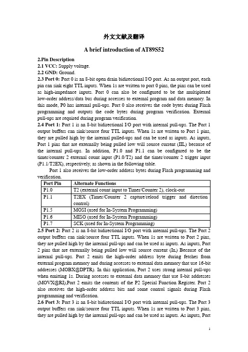
外文文献及翻译A brief introduction of AT89S522.Pin Description2.1 VCC: Supply voltage.2.2 GND: Ground.2.3 Port 0: Port 0 is an 8-bit open drain bidirectional I/O port. As an output port, each pin can sink eight TTL inputs. When 1s are written to port 0 pins, the pins can be used as high-impedance inputs. Port 0 can also be configured to be the multiplexed low-order address/data bus during accesses to external program and data memory. In this mode, P0 has internal pull-ups. Port 0 also receives the code bytes during Flash programming and outputs the code bytes during program verification. External pull-ups are required during program verification.2.4 Port 1: Port 1 is an 8-bit bidirectional I/O port with internal pull-ups. The Port 1 output buffers can sink/source four TTL inputs. When 1s are written to Port 1 pins, they are pulled high by the internal pulled-ups and can be used as inputs. As inputs, Port 1 pins that are externally being pulled low will source current (IIL) because of the internal pull-ups. In addition, P1.0 and P1.1 can be configured to be the timer/counter 2 external count input (P1.0/T2) and the timer/counter 2 trigger input (P1.1/T2EX), respectively, as shown in the following table.Port 1 also receives the low-order address bytes during Flash programming andoutput buffers can sink/source four TTL inputs. When 1s are written to Port 2 pins, they are pulled high by the internal pull-ups and can be used as inputs. As inputs, Port 2 pins that are externally being pulled low will source current (I IL) Because of the internal pull-ups. Port 2 emits the high-order address byte during fetches from external program memory and during accesses to external data memory that use 16-bit addresses (MOBX@DPTR). In this application, Port 2 uses strong internal pull-ups when emitting 1s. During accesses to external data memory that use 8-bit addresses (MOVX@RI),Port 2 emits the contents of the P2 Special Function Register. Port 2 also receives the high-order address bits and some control signals during Flash programming and verification.2.6 Port 3: Port 3 is an 8-bit bidirectional I/O port with internal pull-ups. The Port 3 output buffers can sink/source four TTL inputs. When 1s are written to Port 3 pins, they are pulled high by the internal pull-ups and can be used as inputs. As inputs, Port3 pins that are externally being pulled low will source current (IIL) because of the pull-ups. Port 3 receives some control signals for Flash programming and verification. Port 3 also serves the functions of various special features of the AT89S52, as shownrunning resets the device. This pin drives high for 98 oscillator periods after the Watchdog times out. The DISRTO bit in SFR AUXR (address 8EH) can be used to disable this feature. In the default state of bit DISRTO, the RESET HIGH out feature is enabled.2.8 ALE/PROG: Address Latch Enable (ALE) is an output pulse for latching the low byte of the address during accesses to external memory. This pin is also the programpulse input (PROG) during Flash programming. In normal operation, ALE is emitted at a constant rate of 1/6 the oscillator frequency and may be used for external timing or clocking purposes. Note, however, that one ALE pulse is skipped during each access to external data memory. If desired, ALE operation can be disabled by setting bit 0 or SFR location 8EH. With the bit set, ALE is active only during a MOVX or MOVC instruction. Otherwise, the pin is weakly pulled high. Setting the ALE-disable bit has no effect if the microcontroller is in external execution mode.2.9 PSEN: Program Store Enable (PSEN) is the read strobe to external program memory. When the AT89S52 is executing code from external program memory, PSEN is activated twice each machine cycle, except that two PSEN activations are skipped during each access to external data memory.2.10 EA/VPP: External Access Enable. EA must be strapped to GND in order to enable the device to fetch code from external program memory locations starting at 0000H up to FFFFH. Note, however, that if lock bit 1 is programmed, EA will beinternally latched on reset. EA should be strapped to VCC for internal program executions. This pin also receives the 12-volt programming enable voltage (VPP) during Flash programming.2.11 XTAL1: Input to the inverting oscillator amplifier and input to the internal clock operating circuit.2.12 XTAL2: Output from the inverting oscillator amplifier.3.Memory OrganizationMCS-51 devices have a separate address space for Program and Data Memory. Up to 64K bytes each of external Program and Data Memory can be addressed.3.1 Program MemoryIf the EA pin is connected to GND, all program fetches are directed to external memory. On the AT89S52, if EA is connected to VCC, program fetches to addresses 0000H through 1FFFH are directed to internal memory and fetches to addresses 2000H through FFFFH are to external memory.3.2 Data MemoryThe AT89S52 implements 256 bytes of on-chip RAM. The upper 128 bytes occupy a parallel address space to the Special Function Registers. This means that the upper 128 bytes have the same addresses as the SFR space but are physically separate from SFR space. When an instruction accesses an internal location above address 7FH, the address mode used in the instruction specifies whether the CPU accesses the upper 128 bytes of RAM or the SFR space. Instructions which use direct addressing access the SFR space. For example, the following direct addressing instruction accesses the SFR at location 0A0H (which is P2).MOV 0A0H, #dataInstructions that use indirect addressing access the upper 128 bytes of RAM. For example, the following indirect addressing instruction, where R0 contains 0A0H, accesses the data byte at address 0A0H, rather than P2 (whose address is 0A0H).MOV @R0, #dataNote that stack operations are examples of indirect addressing, so the upper 128 bytes of data RAM are available as stack space.4.Watchdog Timer (One-time Enabled with Reset-out)The WDT is intended as a recovery method in situations where the CPU may be subjected to software upsets. The WDT consists of a 14-bit counter and the Watchdog Timer Reset (WDTRST) SFR. The WDT is defaulted to disable from exiting reset. To enable the WDT, a user must write 01EH and 0E1H in sequence to the WDTRST register (SFR location 0A6H). When the WDT is enabled, it will increment every machine cycle while the oscillator is running. The WDT timeout period is dependent on the external clock frequency. There is no way to disable the WDT except though reset (either hardware reset or WDT overflow reset). When WDT overflows, it will drive an output RESET HIGH pulse at the RST pin.5.UARTThe UART in the AT89S52 operates the same way as the UART in the AT89C51and AT89C52. For further information on the UART operation, please click on the document link below:/dyn/resources/prod_documents/DOC4316.PDF6.Timer 0 and 1Timer 0 and Timer 1 in the AT89S52 operate the same way as Timer 0 and Timer 1 in the AT89C51 and AT89C52. For further information on the timers’operation, please click on the document link below:/dyn/resources/prod_documents/DOC4316.PDF7.Timer 2Timer 2 is a 16-bit Timer/Counter that can operate as either a timer or an event counter. The type of operation is selected by bit C/T2in the SFR T2CON. Timer 2 has three operating modes: capture, auto-reload (up or down counting), and baud rate generator. The modes are selected by bits in T2CON, as shown in Table 6-1. Timer 2 consists of two 8-bit registers, TH2 and TL2. In the Timer function, the TL2 register is incremented every machine cycle. Since a machine cycle consists of 12 oscillator periods, the count rate is 1/12 of the oscillator frequency.transition at its corresponding external input pin, T2. In this function, the external input is sampled during S5P2 of every machine cycle. When the samples show a high in one cycle and a low in the next cycle, the count is incremented. The new count value appears in the register during S3P1 of the cycle following the one in which the transition was detected. Since two machine cycles (24 oscillator periods) are required to recognize a 1-to-0 transition, the maximum count rate is 1/24 of the oscillator frequency. To ensure that a given level is sampled at least once before it changes, the level should be held for at least one full machine cycle.7.1 Capture ModeIn the capture mode, two options are selected by bit EXEN2 in T2CON. If EXEN2=0, Timer 2 is a 16-bit timer or counter which upon overflow sets bit TF2 in T2CON. This bit can then be used to generate an interrupt. If EXEN2=1, Timer 2 performs the same operation, but a 1-to-0 transition at external input T2EX also causes the current value in TH2 and TL2 to be captured into RCAP2H and RCAP2L, respectively. In addition, the transition at T2EX causes bit EXF2 in T2CON to be set. The EXF2 bit, like TF2, can generate an interrupt.7.2 Auto-reload (Up or Down Counter)Timer 2 can be programmed to count up or down when configured in its 16-bit auto-reload mode. This feature is invoked by the DCEN (Down Counter Enable) bitlocated in the SFR T2MOD. Upon reset, the DCEN bit is set to 0 so that timer 2 will default to count up. When DCEN is set, Timer 2 can count up or down, depending on the value of the T2EX pin. Timer 2 automatically counting up when DCEN=0. In this mode, two options are selected by bit EXEN2 in T2CON. If EXEN2=0, Timer 2 counts up to 0FFFFH and then sets the TF2 bit upon overflow. The overflow also causes the timer registers to be reloaded with the 16-bit value in RCAP2H and RCAP2L. The values in Timer in Capture Mode RCAP2H and RCAP2L are preset by software. If EXEN2=1, a 16-bit reload can be triggered either by an overflow or by a 1-to-0 transition at external input T2EX. This transition also sets the EXF2 bit. Both the TF2 and EXF2 bits can generate an interrupt if enabled. Setting the DCEN bit enables Timer 2 to count up or down, as shown in Figure 10-2. In this mode, the T2EX pin controls the direction of the count. A logic 1 at T2EX makes Timer 2 count up. The timer will overflow at 0FFFFH and set the TF2 bit. This overflow also causes the 16-bit value in RCAP2H and RCAP2L to be reloaded into the timer registers, TH2 and TL2, respectively. A logic 0 at T2EX makes Timer 2 count down. The timer underflows when TH2 and TL2 equal the values stored in RCAP2H and RCAP2L. The underflow sets the TF2 bit and causes 0FFFFH to be reloaded into the timer registers. The EXF2 bit toggles whenever Timer 2 overflows or underflows and can be used as a 17th bit of resolution. In the operating mode, EXF2 does not flag an interrupt.8.Baud Rate GeneratorTimer 2 is selected as the baud rate generator by setting TCLK and/or RCLK in T2CON. Note that the baud rates for transmit and receive can be different if Timer 2 is used for the receiver or transmitter and Timer 1 is used for the other function. Setting RCLK and/or TCLK puts Timer 2 into its baud rate generator mode. The baud rate generator mode is similar to the auto-reload mode, in that a rollover in TH2 causes the Timer 2 registers to be reloaded with the 16-bit value in registers RCAP2H and RCAP2L, which are preset by software. The baud rates in Modes 1 and 3 are determined by Timer 2’s overflow rate according to the following equation. Modes 1 and 3 Baud Rates=Timer 2 Overflow Rate 16The Timer can be configured for either timer or counter operation. In most applications, it is configured for timer operation (CP/T2=0). The timer operation is different for Timer 2 when it is used as a baud rate generator. Normally, as a timer, it increments every machine cycle (at 1/12 the oscillator frequency). As a baud rate generator, however, it increments every state time (at 1/2 the oscillator frequency). The baud rate formula is given below.[]Modes 1 and 3Oscillator Frequency Baud Rate 3265536RCAP2H,RCAP2L =⨯- Where (RCAP2H, RCAP2L) is the content of RCAP2H and RCAP2L taken as a 16-bit unsigned integer.This figure is valid only if RCLK or TCLK=1 in T2CON. Note that a rollover inTH2 does not set TF2 and will not generate an interrupt. Note too, that if EXEN2 is set, a 1-to-0 transition in T2EX will set EXF2 but will not cause a reload from (RCAP2H, RCAP2L) to (TH2, TL2). Thus, when Timer 2 is in use as a baud rate generator, T2EX can be used as an extra external interrupt. Note that when Timer 2 is running (TR2=1) as a timer in the baud rate generator mode, TH2 and TL2 should not be read from or written to. Under these conditions, the Timer is incremented every state time, and the results of a read or write may not be accurate. The RCAP2 registers may be read but should not be written to, because a write might overlap a reload and cause write and/or reload errors. The timer should be turned off (clear TR2) before accessing the Timer 2 or RCAP2 registers.9.InterruptsThe AT89S52 has a total of six interrupt vectors: two external interrupts (INT0 and INT1), three timer interrupts (Timers 0,1 and 2), and the serial port interrupt. Each of these interrupt sources can be individually enabled or disabled by setting or clearing a bit in Special Function Register IE. IE also contains a global disable bit, EA, which disables all interrupts at once. Note that bit position IE.6 is unimplemented. User software should not write a 1 to this bit position, since it may be used in future AT89 products. Timer 2 interrupt is generated by the logical OR of bits TF2 and EXF2 in register T2CON. Neither of these flags is cleared by hardware when the service routine is vectored to. In fact, the service routine may have to determine whether it was TF2 or EXF2 that generated the interrupt, and that bit will have to be cleared in software. The Timer 0 and Timer 1 flags, TF0 and TF1, are set at S5P2 of the cycle in which the timers overflow. The values are then polled by the circuitry in the next cycle. However, the Timer 2 flag, TF2, is set at S2P2 and is polled in the same cycle in which the timer overflows.10.Oscillator CharacteristicsXTAL1 and XTAL2 are the input and output, respectively, of an inverting amplifier that can be configured for use as an on-chip oscillator. Either a quartz crystal or ceramic resonator may be used. To drive the device from an external clock source, XTAL2 should be left unconnected while XTAL1 is driven. There are no requirements on the duty cycle of the external clock signal, since the input to the internal clocking circuitry is through a divide-by-two flip-flop, but minimum and maximum voltage high and low time specifications must be observed.AT89S52单片机简介2.引脚功能2.1 VCC:电源2.2 GND:接地2.3 P0:P0口是一个8位开路漏极双向I/O口。
计算机专业中英文翻译(外文翻译、文献翻译)
英文参考文献及翻译Linux - Operating system of cybertimesThough for a lot of people , regard Linux as the main operating system to make up huge work station group, finish special effects of " Titanic " make , already can be regarded as and show talent fully. But for Linux, this only numerous news one of. Recently, the manufacturers concerned have announced that support the news of Linux to increase day by day, users' enthusiasm to Linux runs high unprecedentedly too. Then, Linux only have operating system not free more than on earth on 7 year this piece what glamour, get the favors of such numerous important software and hardware manufacturers as the masses of users and Orac le , Informix , HP , Sybase , Corel , Intel , Netscape , Dell ,etc. , OK?1.The background of Linux and characteristicLinux is a kind of " free (Free ) software ": What is called free,mean users can obtain the procedure and source code freely , and can use them freely , including revise or copy etc.. It is a result of cybertimes, numerous technical staff finish its research and development together through Inte rnet, countless user is it test and except fault , can add user expansion function that oneself make conveniently to participate in. As the most outstanding one in free software, Linux has characteristic of the following:(1)Totally follow POSLX standard, expand the network operatingsystem of supporting all AT&T and BSD Unix characteristic. Because of inheritting Unix outstanding design philosophy , and there are clean , stalwart , high-efficient and steady kernels, their all key codes are finished by Li nus Torvalds and other outstanding programmers, without any Unix code of AT&T or Berkeley, so Linu x is not Unix, but Linux and Unix are totally compatible.(2)Real many tasks, multi-user's system, the built-in networksupports, can be with such seamless links as NetWare , Windows NT , OS/2 , Unix ,etc.. Network in various kinds of Unix it tests to be fastest in comparing and assess efficiency. Support such many kinds of files systems as FAT16 , FAT32 , NTFS , Ex t2FS , ISO9600 ,etc. at the same time .(3) Can operate it in many kinds of hardwares platform , including such processors as Alpha , SunSparc , PowerPC , MIPS ,etc., to various kinds of new-type peripheral hardwares, can from distribute on global numerous programmer there getting support rapidly too.(4) To that the hardware requires lower, can obtain very good performance on more low-grade machine , what deserves particular mention is Linux outstanding stability , permitted " year " count often its running times.2.Main application of Linux At present,Now, the application of Linux mainly includes:(1) Internet/Intranet: This is one that Linux was used most at present, it can offer and include Web server , all such Inter net services as Ftp server , Gopher server , SMTP/POP3 mail server , Proxy/Cache server , DNS server ,etc.. Linux kernel supports IPalias , PPP and IPtunneling, these functions can be used for setting up fictitious host computer , fictitious service , VPN (fictitious special-purpose network ) ,etc.. Operating Apache Web server on Linux mainly, the occupation rate of market in 1998 is 49%, far exceeds the sum of such several big companies as Microsoft , Netscape ,etc..(2) Because Linux has outstanding networking ability , it can be usedin calculating distributedly large-scaly, for instance cartoon making , scientific caculation , database and file server ,etc..(3) As realization that is can under low platform fullness of Unix that operate , apply at all levels teaching and research work of universities and colleges extensively, if Mexico government announce middle and primary schools in the whole country dispose Linux and offer Internet service for student already.(4) Tabletop and handling official business appliedly. Application number of people of in this respect at present not so good as Windows of Microsoft far also, reason its lie in Lin ux quantity , desk-top of application software not so good as Windows application far not merely,because the characteristic of the freedom software makes it not almost have advertisement that support (though the function of Star Office is not second to MS Office at the same time, but there are actually few people knowing).3.Can Linux become a kind of major operating system?In the face of the pressure of coming from users that is strengthened day by day, more and more commercial companies transplant its application to Linux platform, comparatively important incident was as follows, in 1998 ①Compaq and HP determine to put forward user of requirement truss up Linux at their servers , IBM and Dell promise to offer customized Linux system to user too. ②Lotus announce, Notes the next edition include one special-purpose edition in Linux. ③Corel Company transplants its famous WordPerfect to on Linux, and free issue. Corel also plans to move the other figure pattern process products to Linux platform completely.④Main database producer: Sybase , Informix , Oracle , CA , IBM have already been transplanted one's own database products to on Linux, or has finished Beta edition, among them Oracle and Informix also offer technical support to their products.4.The gratifying one is, some farsighted domestic corporations have begun to try hard to change this kind of current situation already. Stone Co. not long ago is it invest a huge sum of money to claim , regard Linux as platform develop a Internet/Intranet solution, regard this as the core and launch Stone's system integration business , plan to set up nationwide Linux technical support organization at the same time , take the lead to promote the freedom software application and development in China. In addition domestic computer Company , person who win of China , devoted to Linux relevant software and hardware application of system popularize too. Is it to intensification that Linux know , will have more and more enterprises accede to the ranks that Linux will be used with domestic every enterprise to believe, more software will be planted in Linux platform. Meanwhile, the domestic university should regard Linux as the original version and upgrade already existing Unix content of courses , start with analysing the source code and revising the kernel and train a large number of senior Linux talents, improve our country's own operating system. Having only really grasped the operating system, the software industry of our country could be got rid of and aped sedulously at present, the passive state led by the nose byothers, create conditions for revitalizing the software industry of our country fundamentally.中文翻译Linux—网络时代的操作系统虽然对许多人来说,以Linux作为主要的操作系统组成庞大的工作站群,完成了《泰坦尼克号》的特技制作,已经算是出尽了风头。
计算机专业毕业外文翻译原文+封面+中文翻译

本科毕业论文外文翻译外文译文题目(中文):具体数学:汉诺塔问题学院: 计算机科学与技术专业: 计算机科学与技术学号:学生姓名:指导教师:日期: 二○一二年六月1 Recurrent ProblemsTHIS CHAPTER EXPLORES three sample problems that give a feel for what’s to c ome. They have two traits in common: They’ve all been investigated repeatedly by mathe maticians; and their solutions all use the idea of recurrence, in which the solution to eac h problem depends on the solutions to smaller instances of the same problem.1.1 THE TOWER OF HANOILet’s look first at a neat little puzzle called the Tower of Hanoi,invented by the Fr ench mathematician Edouard Lucas in 1883. We are given a tower of eight disks, initiall y stacked in decreasing size on one of three pegs:The objective is to transfer the entire tower to one of the other pegs, movingonly one disk at a time and never moving a larger one onto a smaller.Lucas furnished his toy with a romantic legend about a much larger Tower of Brah ma, which supposedly has 64 disks of pure gold resting on three diamond needles. At th e beginning of time, he said, God placed these golden disks on the first needle and orda ined that a group of priests should transfer them to the third, according to the rules abov e. The priests reportedly work day and night at their task. When they finish, the Tower will crumble and the world will end.It's not immediately obvious that the puzzle has a solution, but a little thought (or h aving seen the problem before) convinces us that it does. Now the question arises:What' s the best we can do?That is,how many moves are necessary and suff i cient to perfor m the task?The best way to tackle a question like this is to generalize it a bit. The Tower of Brahma has 64 disks and the Tower of Hanoi has 8;let's consider what happens if ther e are TL disks.One advantage of this generalization is that we can scale the problem down even m ore. In fact, we'll see repeatedly in this book that it's advantageous to LOOK AT SMAL L CASES first. It's easy to see how to transfer a tower that contains only one or two di sks. And a small amount of experimentation shows how to transfer a tower of three.The next step in solving the problem is to introduce appropriate notation:NAME ANO CONQUER. Let's say that T n is the minimum number of moves that will t ransfer n disks from one peg to another under Lucas's rules. Then T1is obviously 1 , an d T2= 3.We can also get another piece of data for free, by considering the smallest case of all:Clearly T0= 0,because no moves at all are needed to transfer a tower of n = 0 disks! Smart mathematicians are not ashamed to think small,because general patterns are easier to perceive when the extreme cases are well understood(even when they are trivial).But now let's change our perspective and try to think big;how can we transfer a la rge tower? Experiments with three disks show that the winning idea is to transfer the top two disks to the middle peg, then move the third, then bring the other two onto it. Thi s gives us a clue for transferring n disks in general:We first transfer the n−1 smallest t o a different peg (requiring T n-1moves), then move the largest (requiring one move), and finally transfer the n−1 smallest back onto the largest (req uiring another T n-1moves). Th us we can transfer n disks (for n > 0)in at most 2T n-1+1 moves:T n≤2T n—1+1,for n > 0.This formula uses '≤' instead of '=' because our construction proves only that 2T n—1+1 mo ves suffice; we haven't shown that 2T n—1+1 moves are necessary. A clever person might be able to think of a shortcut.But is there a better way? Actually no. At some point we must move the largest d isk. When we do, the n−1 smallest must be on a single peg, and it has taken at least T moves to put them there. We might move the largest disk more than once, if we're n n−1ot too alert. But after moving the largest disk for the last time, we must trans fr the n−1 smallest disks (which must again be on a single peg)back onto the largest;this too re quires T n−1moves. HenceT n≥ 2T n—1+1,for n > 0.These two inequalities, together with the trivial solution for n = 0, yieldT0=0;T n=2T n—1+1 , for n > 0. (1.1)(Notice that these formulas are consistent with the known values T1= 1 and T2= 3. Our experience with small cases has not only helped us to discover a general formula, it has also provided a convenient way to check that we haven't made a foolish error. Such che cks will be especially valuable when we get into more complicated maneuvers in later ch apters.)A set of equalities like (1.1) is called a recurrence (a. k. a. recurrence relation or r ecursion relation). It gives a boundary value and an equation for the general value in ter ms of earlier ones. Sometimes we refer to the general equation alone as a recurrence, alt hough technically it needs a boundary value to be complete.The recurrence allows us to compute T n for any n we like. But nobody really like to co m pute fro m a recurrence,when n is large;it takes too long. The recurrence only gives indirect, "local" information. A solution to the recurrence would make us much h appier. That is, we'd like a nice, neat, "closed form" for Tn that lets us compute it quic kly,even for large n. With a closed form, we can understand what T n really is.So how do we solve a recurrence? One way is to guess the correct solution,then to prove that our guess is correct. And our best hope for guessing the solution is t o look (again) at small cases. So we compute, successively,T3= 2×3+1= 7; T4= 2×7+1= 15; T5= 2×15+1= 31; T6= 2×31+1= 63.Aha! It certainly looks as ifTn = 2n−1,for n≥0. (1.2)At least this works for n≤6.Mathematical induction is a general way to prove that some statement aboutthe integer n is true for all n≥n0. First we prove the statement when n has its smallest v alue,no; this is called the basis. Then we prove the statement for n > n0,assuming that it has already been proved for all values between n0and n−1, inclusive; this is called th e induction. Such a proof gives infinitely many results with only a finite amount of wo rk.Recurrences are ideally set up for mathematical induction. In our case, for exampl e,(1.2) follows easily from (1.1):The basis is trivial,since T0 = 20−1= 0.And the indu ction follows for n > 0 if we assume that (1.2) holds when n is replaced by n−1:T n= 2T n+1= 2(2n−1−1)+1=2n−1.Hence (1.2) holds for n as well. Good! Our quest for T n has ended successfully.Of course the priests' task hasn't ended;they're still dutifully moving disks,and wil l be for a while, because for n = 64 there are 264−1 moves (about 18 quintillion). Even at the impossible rate of one move per microsecond, they will need more than 5000 cent uries to transfer the Tower of Brahma. Lucas's original puzzle is a bit more practical, It requires 28−1 = 255 moves, which takes about four minutes for the quick of hand.The Tower of Hanoi recurrence is typical of many that arise in applications of all kinds. In finding a closed-form expression for some quantity of interest like T n we go t hrough three stages:1 Look at small cases. This gives us insight into the problem and helps us in stages2 and 3.2 Find and prove a mathematical expression for the quantity of interest.For the Tower of Hanoi, this is the recurrence (1.1) that allows us, given the inc lination,to compute T n for any n.3 Find and prove a closed form for our mathematical expression.For the Tower of Hanoi, this is the recurrence solution (1.2).The third stage is the one we will concentrate on throughout this book. In fact, we'll fre quently skip stages I and 2 entirely, because a mathematical expression will be given tous as a starting point. But even then, we'll be getting into subproblems whose solutions will take us through all three stages.Our analysis of the Tower of Hanoi led to the correct answer, but it r equired an“i nductive leap”;we relied on a lucky guess about the answer. One of the main objectives of this book is to explain how a person can solve recurrences without being clairvoyant. For example, we'll see that recurrence (1.1) can be simplified by adding 1 to both sides of the equations:T0+ 1= 1;T n + 1= 2T n-1+ 2, for n >0.Now if we let U n= T n+1,we haveU0 =1;U n= 2U n-1,for n > 0. (1.3)It doesn't take genius to discover that the solution to this recurrence is just U n= 2n;he nce T n= 2n −1. Even a computer could discover this.Concrete MathematicsR. L. Graham, D. E. Knuth, O. Patashnik《Concrete Mathematics》,1.1 ,The Tower Of HanoiR. L. Graham, D. E. Knuth, O. PatashnikSixth printing, Printed in the United States of America1989 by Addison-Wesley Publishing Company,Reference 1-4 pages具体数学R.L.格雷厄姆,D.E.克努特,O.帕塔希尼克《具体数学》,1.1,汉诺塔R.L.格雷厄姆,D.E.克努特,O.帕塔希尼克第一版第六次印刷于美国,韦斯利出版公司,1989年,引用1-4页1 递归问题本章将通过对三个样本问题的分析来探讨递归的思想。
可燃气体报警器中英文对照外文翻译文献
可燃气体报警器中英文对照外文翻译文献(文档含英文原文和中文翻译)原文:Design of Combustible Gas Detection system using WirelessKeywords:TGS813, AT89S52, DS18B20, nRF905, TC35iAbstract.The detection device of combustible gas are designed in the presented work,using wireless transceiver and GSM network.The system realize the wireless transmission of the gas concentration,and also can send alarm information to user’s mobile when an exception occurs.The system consists of two parts: a master and slave. The function of the slave is to collect data, process data and transffer the data to the master.The taskof the master is to receive data and display it by LED.The signal acquisition is completed by sensor TGS813 and A/D converter TLC2543. Thewireless transmission is achieved through wireless transceiver nRF905. Since the accuracy of thesensor is affected by the environment,using DS18B20 to achieve temperature compensation.And with wireless communication module TC35i and GSM network platform, we can send thealarm information to use r’s mobile promptly.IntroductionGas detection is widely used in petroleum, chemical, metallurgy, family, shopping malls,gas stations and other places. Currently, how to monitor the hazardous gas fast and accuratelyare the important issues. Although the gas detection technology is relatively mature, but mostproducts has many shortcomings, such as single function, operating complex, bulky, expensiveand low sensitivity. Wireless communication technology applied to the gas monitoring field, canresolve the problem of remote monitoring in special environment, such as high temperature, low temperature, toxic gas.and unable to wiring .In the presented work, the combustible gas detectoris fully functional (with wireless transceiver), simple, small size, low cost, and has high sensitivity. The equipment can greatlyimprove the system's detection capability and accuracy with temperature compensation algorithm, and also can send alarm information to the user's mobile phone promptly through theGSM network.System designThe system consists of two parts as shown in Figure 1.Fig. 1 Overall system block diagramThe slave part mainly complete data collection and wireless transmission. The master part mainly complete receiving data, displaying and sending alarm message.The signal of gas concentration is collected by combustible gas sensor which generates a weak electrical signal. The signal can be amplified and stabilized by conditioning circuit. And then A/D circuit converts the analog signal to digital signal which microcontroller can process. In order to improve the measurement accuracy, and reduce the impact of temperature, design a temperature compensation circuit to collect tempreture data. AT89S52 process the collected data and send data to the master by wireless transceiver.The master receives the data and displays it by LED. And if the gas concentration being abnormal,the system will drive speaker for an alarm signal and use TC35i module to send alarm information to user’s mobile.Hardware designSignal acquisition and conditioning circuit. Figure 2 shows data acquisition circuit. TGS813 is a Gas sensing resistive sensor. The conductivity of TGS813 is influenced by the concentration of combustible gases in air, the greater the concentration, the higher conductivity. In system R0, R9, R10 and RS (inTGS813) form a bridge circuit to convert resistance to voltage signal. Operational amplifier A connected as a voltage follower with resistors R7 and regulator D1 make up the voltage regulator circuit to supply power for the bridge. In order to the voltage adapt to the A/D converter, the voltage is amplified by opamp B, and the magnification can be adjusted through resistor R11.Fig. 2 Gas concentration signal acquisition circuitFig. 3 Temperature compensation circuitTemperature compensation circuit. The resistance of Rs is greatly affected by temperature. In order to improve system accuracy, the results must be temperature compensated or temperature correction.In system, using temperature sensor DS1820 to collect temperature signal, and using software method for temperature correction.Wireless transmission module. Wireless transceiver is achieved by a single-chip RF transceiver nRF905. MCU and nRF905 realize data and commands interaction through the SPI interface.The typical application schematic is shown in Figure 4. The antenna part is 50Ω single-ended antenna.The communication frequency is 433MHz, and operating voltage is3.3V. The value of resistors,capacitors and inductor is determined by the datasheet of nRF905. GSM short message unit. The interface circuit of TC35i and MCU is shown in Figure 5. The communication between MCU and TC35i is via serial, and the rate is 9600bps. Communicationsmode is 8-bit asynchronous with a start bit, 8 data bits, and 1 stop bit. But the serial input of TC35i requires CMOS level, and serial output of 89C52 requires TTL level. In order to achieve the voltage conversion the system use the way of resistors sharing voltage. Fig. 4 nRF905 Application SchematicFig. 5 TC35i and MCU interface circuitSoftware DesignThe software system includes data acquisition module, temperature compensation module, and wireless transceiver moduleWireless sending program. NRF905 data sending process is as follows:1) When having data to send, the microcontroller send the receiver's address and the data to nRF905 chronologically by the SPI interface.Then placed the data to be transmitted into TxBuf register, send WTP command to write the data to TX-Payload register, and send WTA command to write TX address to the TX-Address register.2) The microcontroller set TRX_CE=1 and TX_EN=1 to stimulate nRF905 ShockBurstTM sending mode. When data transmission completed, the data ready pin is set high;3) Beacause of AUTO_RETRAN being high, the data of nRF905 is constantly re-issued untilTRX_CE=0.4) when TRX_CE pin is set low, means the data transmission completed and nRF905 enter idlemode.Wireless receiving program. NRF905 data receiving process is as follows:1)When TRX_CE = 1 and TX_EN = 0, nRF905 enters ShockBurstTM receive modechecking constantly and waiting for receiving data.2)When nRF905 detect the carrier having same frequency band, the carrier detect pin will beset high.3)When nRF905 receive a matched address, the address matches pin will be set high.4) When packet correctly received, the word head, address and CRC bits will automatically be removed, and the data ready pin will be set high.5) MCU set TRX_CE to "0", and nRF905 enter to idle mode.6) When all the data received, nRF905 set data ready pin and address matching pin to "0", and nRF905 turn to shutdown mode or ShockBurstTM transmitmode and receive mode.Fig.6 Wireless data transmission flow chartFig.7 Wireless data receiving flow chartSummaryDesigned an equipment to detect the concentration of combustible gas, which has wireless transceiver functions and can send the alarm information to user’s mobile promptly through GSM.Experimental results show that the devices have high precision, stability and reliability. It can meet most applications which need real-time monitoring of combustible gas concentration.References[1] Liu S, Chen Q, Wang H G, eat. Electrical capacitance tomography for gas solids flow measurement for circulating fluidized beds [J].Flow Measurement and Instrumentation,2005,16(2-3):135-144.[2] TGS 813-for the Detection of Combustible Gases [DB/OL].2009-08-12.[3] Liu Wei, Chen HeXin,Zhang JunWei,etc. Intelligent control and alarm system based on TC35i. IEEE.2008 International Symposium on Computer Science and Computational Technology(ISCSCT), Shanghai, 2008:80-83译文:使用无线的可燃气体检测系统的设计关键词:TGS813,AT89S52单片机,DS18B20,nRF905,TC35i摘要;可燃气体检测装置是在所提出的工作设计,使用无线收发器和GSM网络。
计算机科学与技术 外文翻译 英文文献 中英对照

附件1:外文资料翻译译文大容量存储器由于计算机主存储器的易失性和容量的限制, 大多数的计算机都有附加的称为大容量存储系统的存储设备, 包括有磁盘、CD 和磁带。
相对于主存储器,大的容量储存系统的优点是易失性小,容量大,低成本, 并且在许多情况下, 为了归档的需要可以把储存介质从计算机上移开。
术语联机和脱机通常分别用于描述连接于和没有连接于计算机的设备。
联机意味着,设备或信息已经与计算机连接,计算机不需要人的干预,脱机意味着设备或信息与机器相连前需要人的干预,或许需要将这个设备接通电源,或许包含有该信息的介质需要插到某机械装置里。
大量储存器系统的主要缺点是他们典型地需要机械的运动因此需要较多的时间,因为主存储器的所有工作都由电子器件实现。
1. 磁盘今天,我们使用得最多的一种大量存储器是磁盘,在那里有薄的可以旋转的盘片,盘片上有磁介质以储存数据。
盘片的上面和(或)下面安装有读/写磁头,当盘片旋转时,每个磁头都遍历一圈,它被叫作磁道,围绕着磁盘的上下两个表面。
通过重新定位的读/写磁头,不同的同心圆磁道可以被访问。
通常,一个磁盘存储系统由若干个安装在同一根轴上的盘片组成,盘片之间有足够的距离,使得磁头可以在盘片之间滑动。
在一个磁盘中,所有的磁头是一起移动的。
因此,当磁头移动到新的位置时,新的一组磁道可以存取了。
每一组磁道称为一个柱面。
因为一个磁道能包含的信息可能比我们一次操作所需要得多,所以每个磁道划分成若干个弧区,称为扇区,记录在每个扇区上的信息是连续的二进制位串。
传统的磁盘上每个磁道分为同样数目的扇区,而每个扇区也包含同样数目的二进制位。
(所以,盘片中心的储存的二进制位的密度要比靠近盘片边缘的大)。
因此,一个磁盘存储器系统有许多个别的磁区, 每个扇区都可以作为独立的二进制位串存取,盘片表面上的磁道数目和每个磁道上的扇区数目对于不同的磁盘系统可能都不相同。
磁区大小一般是不超过几个KB; 512 个字节或1024 个字节。
- 1、下载文档前请自行甄别文档内容的完整性,平台不提供额外的编辑、内容补充、找答案等附加服务。
- 2、"仅部分预览"的文档,不可在线预览部分如存在完整性等问题,可反馈申请退款(可完整预览的文档不适用该条件!)。
- 3、如文档侵犯您的权益,请联系客服反馈,我们会尽快为您处理(人工客服工作时间:9:00-18:30)。
XXXXX学院毕业设计(论文)外文资料翻译学院(系):电子电气工程学院专业:电气工程及其自动化姓名: XXXXX学号: XXXXXXXXXX外文出处:(用外文写)附件: 1.外文资料翻译译文;2.外文原文。
指导教师评语:签名:年月日附件1:外文资料翻译译文AT89S52功能特性描述AT89S52是一种低功耗、高性能CMOS8位微控制器,具有8K 在系统可编程Flash 存储器。
使用 Atmel 公司高密度非易失性存储器技术制造,与工业 80C51 产品指令和引脚完全兼容。
片上Flash允许程序存储器在系统可编程,亦适于常规编程器。
在单芯片上,拥有灵巧的8位 CPU 和在系统可编程Flash,使得 AT89S52为众多嵌入式控制应用系统提供高灵活、超有效的解决方案。
AT89S52具有以下标准功能:8k字节Flash, 256字节RAM,32 位 I/O 口线,看门狗定时器,2 个数据指针,三个 16 位定时器/计数器,一个6向量 2级中断结构,全双工串行口,片内晶振及时钟电路。
另外,AT89S52 可降至 0Hz 静态逻辑操作,支持2种软件可选择节电模式。
空闲模式下,CPU停止工作,允许RAM、定时器/计数器、串口、中断继续工作。
断电保护方式下,RAM内容被保存,振荡器被冻结,单片机一切工作停止,直到下一个中断或硬件复位为止。
VCC:电源GND:接地P0 口:P0口是一个8位漏极开路的双向I/O口。
作为输出口,每位能驱动8个TTL 逻辑电平。
对P0端口写“1”时,引脚用作高阻抗输入。
当访问外部程序和数据存储器时,P0口也被作为低8位地址/数据复用。
在这种模式下,P0具有内部上拉电阻。
在 flash编程时,P0口也用来接收指令字节;在程序校验时,输出指令字节。
程序校验时,需要外部上拉电阻。
P1口:P1口是一个具有内部上拉电阻的8位双向I/O口,p1输出缓冲器能驱动4个TTL 逻辑电平。
对 P1 端口写“1”时,内部上拉电阻把端口拉高,此时可以作为输入口使用。
作为输入使用时,被外部拉低的引脚由于内部电阻的原因,将输出电流(IIL)。
此外,P1.0和P1.2分别作定时器/计数器2的外部计数输入(P1.0/T2)和时器/计数器2的触发输入(P1.1/T2EX),具体如下表所示。
在flash编程和校验时,P1口接收低8位地址字节。
引脚号次要功能P1.0 T2(定时器/计数器T2的外部计数输入),时钟输出P1.1 T2EX(定时器/计数器T2的捕捉/重载触发信号和方向控制)P1.5 MOSI(在系统编程用)P1.6 MISO(在系统编程用)P1.7 SCK(在系统编程用)P2口:P2口是一个具有内部上拉电阻的8位双向I/O口,P2输出缓冲器能驱动4个TTL 逻辑电平。
对P2端口写“1”时,内部上拉电阻把端口拉高,此时可以作为输入口使用。
作为输入使用时,被外部拉低的引脚由于内部电阻的原因,将输出电流(IIL)。
在访问外部程序存储器或用16位地址读取外部数据存储器(例如执行MOVX @DPTR)时,P2口送出高八位地址。
在这种应用中,P2口使用很强的内部上拉发送1。
在使用8位地址(如MOVX @RI)访问外部数据存储器时,P2口输出P2锁存器的内容。
在flash编程和校验时,P2口也接收高8位地址字节和一些控制信号。
P3口:P3口是一个具有内部上拉电阻的8位双向I/O口,p2输出缓冲器能驱动4个TTL逻辑电平。
对P3端口写“1”时,内部上拉电阻把端口拉高,此时可以作为输入口使用。
作为输入使用时,被外部拉低的引脚由于内部电阻的原因,将输出电流(IIL)。
P3口亦作为AT89S52特殊功能(次要功能)使用,如下表所示。
在flash编程和校验时,P3口也接收一些控制信号。
引脚号次要功能P3.0 RXD(串行输入)P3.1 TXD(串行输出)P3.2 0INT(外部中断 0)P3.3 0INT(外部中断 0)P3.4 T0(定时器0外部输入)P3.5 T1(定时器1外部输入)P3.6 WR(外部数据存储器写选通)P3.7 RD(外部数据存储器写选通)RST:复位输入。
晶振工作时,RST脚持续2个机器周期高电平将使单片机复位。
看门狗计时完成后,RST脚输出96个晶振周期的高电平。
特殊寄存器AUXR(地址8EH)上的DISRTO位可以使此功能无效。
DISRTO默认状态下,复位高电平有效。
ALE/PROG:地址锁存控制信号(ALE)是访问外部程序存储器时,锁存低 8 位地址的输出脉冲。
在flash编程时,此引脚(PROG)也用作编程输入脉冲。
在一般情况下,ALE以晶振六分之一的固定频率输出脉冲,可用来作为外部定时器或时钟使用。
然而,特别强调,在每次访问外部数据存储器时,ALE脉冲将会跳过。
如果需要,通过将地址为8EH的SFR的第0位置“1”,ALE操作将无效。
这一位置“1”,ALE仅在执行MOVX或MOVC指令时有效。
否则,ALE将被微弱拉高。
这个ALE 使能标志(地址为8EH的SFR的第0位)的设置对微控制器处于外部执行模式下无效。
PSEN:外部程序存储器选通信号(PSEN)是外部程序存储器选通信号。
当AT89S52从外部程序存储器执行外部代码时,PSEN在每个机器周期被激活两次,而在访问外部数据存储器时,PSEN将不被激活。
EA/VPP:访问外部程序存储器控制信号。
为使能从0000H到FFFFH的外部程序存储器读取指令,EA必须接GND。
为了执行内部程序指令,EA应该接VCC。
在flash编程期间,EA也接收12伏VPP电压。
XTAL1:振荡器反相放大器和内部时钟发生电路的输入端。
XTAL2:振荡器反相放大器的输出端。
表 1 AT89S52特殊寄存器映象及复位值特殊功能寄存器特殊功能寄存器(SFR)的地址空间映象如表1所示。
并不是所有的地址都被定义了。
片上没有定义的地址是不能用的。
读这些地址,一般将得到一个随机数据;写入的数据将会无效。
用户不应该给这些未定义的地址写入数据“1”。
由于这些寄存器在将来可能被赋予新的功能,复位后,这些位都为“0”。
定时器2寄存器:寄存器T2CON和T2MOD包含定时器2的控制位和状态位(如表2和表3所示),寄存器对RCAP2H和RCAP2L是定时器2的捕捉/自动重载寄存器。
中断寄存器:各中断允许位在IE寄存器中,六个中断源的两个优先级也可在IE中设置。
表 2 T2CON:定时器/计数器2控制寄存器T2CON 地址为0C8H 复位值:0000 0000B位可寻址符号功能 TF2 定时器2溢出标志位。
必须软件清“0”。
RCLK=1或TCLK=1时,TF2不用置位。
EXF2 定时器2外部标志位。
EXEN2=1时,T2EX 上的负跳变而出现捕捉或重载时,EXF2会被硬件置位。
定时器2打开,EXF2=1时,将引导 CPU 执行定时器2中断程序。
EXF2必须如见清“0”。
在向下/向上技术模式(DCEN=1)下EXF2不能引起中断。
RCLK 串行口接收数据时钟标志位。
若 RCLK=1,串行口将使用定时器2溢出脉冲作为串行口工作模式1和3的串口接收时钟;RCLK =0,将使用定时器1计数溢出作为串口接收时钟。
TCLK 串行口发送数据时钟标志位。
若TCLK=1,串行口将使用定时器2溢出脉冲作为串行口工作模式1和3的串口发送时钟;TCLK =0,将使用定时器1计数溢出作为串口发送时钟。
EXEN2 定时器2外部允许标志位。
当EXEN2=1时,如果定时器2没有用作串行时钟,T2EX (P1.1)的负跳变见引起定时器2捕捉和重载。
若 EXEN2=0,定时器2将视T2EX 端的信号无效TR2开始/停止控制定时器2。
TR2=1,定时器2开始工作 C/2T 定时器2定时/计数选择标志位。
C/2T =0,定时;C/2T =1,外部事件计数(下降沿触发)CP/2RL 捕捉/重载选择标志位。
当EXEN2=1时,CP/2RL =1,T2EX出现负脉冲,会引起捕捉操作;当定时器2溢出或EXEN2=1时T2EX 出现负跳变,都会出现自动重载操作。
CP/2RL =0将引起T2EX 的负脉冲。
当RCKL=1或TCKL =1时,此标志位无效,定时器2溢出时,强制做自动重载操作。
双数据指针寄存器:为了更有利于访问内部和外部数据存储器,系统提供了两路16位数据指针寄存器:位于SFR中82H~83H的DP0和位于84H~85。
特殊寄存器AUXR1中DPS=0选择DP0;DPS=1选择DP1。
用户应该在访问数据指针寄存器前先初始化DPS至合理的值。
表3a AUXR:辅助寄存器AUXR 地址:8EH 复位值:XXX00XX0B不可位寻址- - - WDIDLE DISRTO - - DISALE7 6 5 4 3 2 1 0- 预留扩展用DISALE ALE使能标志位DISALE 操作方式0 ALE以1/6晶振频率输出信号1 ALE只有在执行MOVX 或MOVC指令时激活DISRTO 复位输出标志位DISRTO0 看门狗(WDT)定时结束,Reset 输出高电平1 Reset 只有输入WDIDLE 空闲模式下WDT使能标志位WDIDLE0 空闲模式下,WDT继续计数1 空闲模式下,WDT停止计数断电标志位:掉电标志位(POF)位于特殊寄存器PCON的第四位(PCON.4)。
上电期间POF置“1”。
POF可以软件控制使用与否,但不受复位影响。
表 3b AUXR1:辅助寄存器1AUXR1 地址:A2H 复位值:XXXXXXX0B不可位寻址- - - - - - - DPS7 6 5 4 3 2 1 0- 预留扩展用DPS 数据指针选择位DPS0 选择DPTR寄存器DP0L和DP0H1 选择DPTR寄存器DP1L和DP1H存储器结构MCS-51器件有单独的程序存储器和数据存储器。
外部程序存储器和数据存储器都可以64K寻址。
程序存储器:如果EA引脚接地,程序读取只从外部存储器开始。
对于89S52,如果EA接VCC,程序读写先从内部存储器(地址为0000H~1FFFH)开始,接着从外部寻址,寻址地址为:2000H~FFFFH。
数据存储器:AT89S52有256字节片内数据存储器。
高128字节与特殊功能寄存器重叠。
也就是说高128字节与特殊功能寄存器有相同的地址,而物理上是分开的。
当一条指令访问高于7FH的地址时,寻址方式决定CPU访问高128字节RAM还是特殊功能寄存器空间。
直接寻址方式访问特殊功能寄存器(SFR)。
例如,下面的直接寻址指令访问0A0H(P2口)存储单元MOV 0A0H , #data使用间接寻址方式访问高128字节RAM。
例如,下面的间接寻址方式中,R0内容为0A0H,访问的是地址0A0H的寄存器,而不是P2口(它的地址也是0A0H)。