通用型压力传感器KL11系列
First Sensor MLH系列金属压力传感器产品说明书
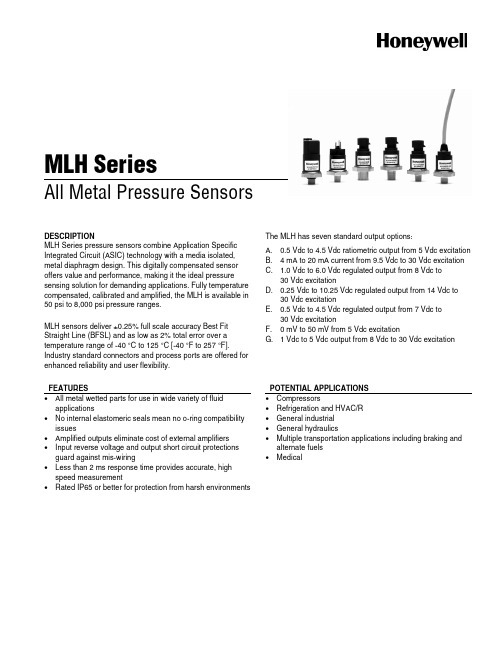
MLH SeriesAll Metal Pressure SensorsDESCRIPTIONMLH Series pressure sensors combine Application Specific Integrated Circuit (ASIC) technology with a media isolated, metal diaphragm design. This digitally compensated sensor offers value and performance, making it the ideal pressure sensing solution for demanding applications. Fully temperature compensated, calibrated and amplified, the MLH is available in 50 psi to 8,000 psi pressure ranges.MLH sensors deliver ±0.25% full scale accuracy Best Fit Straight Line (BFSL) and as low as 2% total error over a temperature range of -40 °C to 125 °C [-40 °F to 257 °F]. Industry standard connectors and process ports are offered for enhanced reliability and user flexibility.The MLH has seven standard output options:A. 0.5 Vdc to 4.5 Vdc ratiometric output from 5 Vdc excitationB. 4 mA to 20 mA current from 9.5 Vdc to 30 Vdc excitationC. 1.0 Vdc to 6.0 Vdc regulated output from 8 Vdc to30 Vdc excitationD. 0.25 Vdc to 10.25 Vdc regulated output from 14 Vdc to30 Vdc excitationE. 0.5 Vdc to 4.5 Vdc regulated output from 7 Vdc to30 Vdc excitationF. 0 mV to 50 mV from 5 Vdc excitationG. 1 Vdc to 5 Vdc output from 8 Vdc to 30 Vdc excitationFEATURES• All metal wetted parts for use in wide variety of fluidapplications• No internal elastomeric seals mean no o-ring compatibilityissues• Amplified outputs eliminate cost of external amplifiers • Input reverse voltage and output short circuit protectionsguard against mis-wiring• Less than 2 ms response time provides accurate, highspeed measurement• Rated IP65 or better for protection from harsh environmentsPOTENTIAL APPLICATIONS • Compressors• Refrigeration and HVAC/R • General industrial • General hydraulics• Multiple transportation applications including braking andalternate fuels • MedicalMLH Series2 /sensingTable 1. Pressure Range Specifications 1(At 25 °C [77 °F] and at rated excitation unless otherwise specified.)psiPressure 50 100 150 200 250 300 500 1000 2000 3000 5000 8000 Proof pressure 150 300 450 600 750 900 1500 2000 4000 6000 7500 12000 Burst pressure 500 1000 1500 2000 2500 3000 5000 10000 20000 30000 30000 30000barPressure 6 10 16 25 40 60 100 160 250 350 500 550 Proof pressure 18 30 48 75 80 120 200 320 500 700 750 825 Burst pressure60 100 160 250 400 600 1000 1600 2068 2068 2068 2068Note:1. Comparable metric units follow same proof and burst specifications.Table 2. Physical and Environmental SpecificationsParameter Characteristic Material in contact with media stainless steel 300 series and Haynes 214 alloy, Hastelloy C22 sensor available (contact factory) Housing material black plastic – Amodel AS-4133 HS – PPA Weight 57.0 g [2.0 oz] (typical for Packard MetriPak and 1/8 NPT port) Shock 100 g peak [11 ms] Vibration MIL-STD-810C, Figure 514.2-5, Curve AK, Table 514.2-V, Random Vibration Test [overall g rms =20.7 min.]Compensated, operating and storage temperature range-40 °C to 125 °C [-40 °F to 257 °F]Table 3. Electrical Specifications (At 25 °C [77 °F] and at rated excitation unless otherwise specified.) Parameter Ratiometric(A)1 Current (B) Regulated(C) Regulated(D) Regulated(E) mV (F) Regulated(G) Zero output 0.5 Vdc4.0 mA1.0 Vdc0.25 Vdc0.5 Vdc0 ±2.5 mV1.0 VdcFull scale span (FSS) 4.0 Vdc (0.5 to 4.5 Vdc) 16 mA (4 to 20 mA) 5.0 Vdc (1.0 to 6.0 Vdc) 10.0 Vdc (0.25 to 10.25 Vdc) 4.0 Vdc (0.5 to4.5 Vdc) 50 mV (0 to 50 mV) 4.0 Vdc (1.0 to 5.0 Vdc)Excitation 5 Vdc (6.0 Vdc max.) 9.5 Vdc to 30.0 Vdc 8.0 Vdc to 30.0 Vdc 14.0 Vdc to 30.0 Vdc 7.0 Vdc to 30.0 Vdc5.0 Vdc (6.0 Vdc max.)8.0 Vdc to 30.0 VdcSupply current 4.0 mA typical (8 mA max.)N/A 5.0 mA typical (17 mA max.)5.0 mA typical (17 mA max.)5.0 mA typical (17 mA max.) 8.0 mA typical (17 mA max.) 5.0 mA typical (17 mA max.)Source (nominal) 1.0 mA N/A 1.0 mA 1.0 mA 1.0 mA N/A 1.0 mA Sink(nominal) 1.0 mA at zero outputN/A 1.0 mA at zero output1.0 mA at zero output1.0 mA at zero outputN/A 1.0 mA at zero outputSupplyrejection ratio 90 db 90 db 90 db 90 db 90 db N/A90 dbOutput impedance25 Ω max.N/A25 Ω max.25 Ω max.25 Ω max.2000 Ω 25 Ω max.Note:1. Maintains ratiometricity at 5 ±0.25 Vdc excitation. Product can tolerate 6 Vdc excitation without damage.All Metal Pressure SensorsHoneywell Sensing and Control 3Table 4. Performance Specifications (At 25 °C [77 °F] and at rated excitation unless otherwise specified.)Parameter Characteristic Response time <2 msAccuracy 1:>100 psi<100 psi±0.25% FSS ±0.50% FSS Total error band 2:Gage:<300 psig>300 psigSeal gage:>300 psisSeal gage without L, M, P termination:100 psis to 299 psis (-40 °C to 85 °C [-40 °F to 185 °F])100 psis to 299 psis (>85 °C to 125 °C [>185 °F to 257 °F])>300 psis (-40 °C to 125 °C [-40 °F to 257 °F])Seal gage with L, M, P termination:100 psis to 299 psis (-40 °C to 65 °C [-40 °F to 149 °F])100 psis to 299 psis (>65 °C to 125 °C [>149 °F to 257 °F])>300 psis (-40 °C to 65 °C [-40 °F to 149 °F])>300 psis (>65 °C to 125 °C [>149 °F to 257 °F])±3% FSS ±2% FSS ±2% FSS ±3% FSS ±10% FSS ±2% FSS ±10% FSS ±15% FSS ±5% FSS ±15% FSS Notes:1. Includes pressure non-linearity (BFSL), pressure hysteresis and non-repeatability. Thermal errors are not included.2. Includes zero error, span error, thermal effect on zero, thermal effect on span, thermal hysteresis, pressure-non-linearity,pressure hysteresis and non-repeatability.1Sensing and Control Honeywell1985 Douglas Drive North Golden Valley, MN 55422 /sensing 008118-5-EN IL50 GLO Printed in USAJanuary 2009Copyright © 2009. Honeywell International Inc. All rights reserved.Figure 2. Mounting Dimensions (For reference only. mm/(in).)Pin and Wire Codes (Option B – Packard)Pin Voltage Current a + Excitation + Excitation b Output - Excitation c Common No ConnectionA variety of pressure ports and electricaltermination connection options are available. Refer to the “How to Order” on previous page for possible combinations. Contact your Honeywell representative for details.WARNINGMISUSE OF DOCUMENTATION• The information presented in this product sheet is forreference only. Do not use this document as a product installation guide.• Complete installation, operation, and maintenanceinformation is provided in the instructions supplied with each product.Failure to comply with these instructions could result in death or serious injury.WARRANTY/REMEDYHoneywell warrants goods of its manufacture as being free of defective materials and faulty workmanship. Honeywell’s standard product warranty applies unless agreed to otherwise by Honeywell in writing; please refer to your order acknowledgement or consult your local sales office for specific warranty details. If warranted goods are returned to Honeywell during the period of coverage, Honeywell will repair or replace, at its option, without charge those items it finds defective. Theforegoing is buyer’s sole remedy and is in lieu of all other warranties, expressed or implied, including those of merchantability and fitness for a particular purpose. In no event shall Honeywell be liable for consequential, special, or indirect damages.While we provide application assistance personally,through our literature and the Honeywell web site, it is up to the customer to determine the suitability of the product in the application.Specifications may change without notice. Theinformation we supply is believed to be accurate and reliable as of this printing. However, we assume no responsibility for its use.WARNINGPERSONAL INJURYDO NOT USE these products as safety or emergency stop devices or in any other application where failure of the product could result in personal injury.Failure to comply with these instructions could result in death or serious injury.SALES AND SERVICEHoneywell serves its customers through a worldwide network of sales offices, representatives and distributors. For application assistance, current specifications, pricing or name of the nearest Authorized Distributor, contact your local sales office or:E-mail:*********************Internet: /sensingPhone and Fax: Asia Pacific +65 6355-2828 +65 6445-3033 Fax Europe +44 (0) 1698 481481 +44 (0) 1698 481676 Fax Latin America +1-305-805-8188 +1-305-883-8257 F ax USA/Canada +1-800-537-6945 +1-815-235-6847 +1-815-235-6545 F ax。
202006 - 第6章 硅压阻式传感器【传感器技术案例教程】

d L L σL — 轴向应力 (Pa); πL — 压阻系数(Pa-1 ),单位应力引起电阻率相对变化量
电阻变化率
dR R
d
dL L
2
dL L
L E
2
1 L
KL
常用半导体材料弹性模量 1.3×10¹¹~1.9×10¹¹ Pa,压阻系数 50×10-11~138×10-11 Pa-1,故 πLE 范围 65~265;半导体压阻 效应等效应变灵敏系数远大于金属
n 12 11 12 44 0 12
(001)面上<010>晶向 纵向、横向示意图
→ 对 P 型硅,本算例压阻效应为零;应采用 N 型硅
(第6章 硅压阻式传感器)
6.1 硅压阻式变换原理
6.1.3 压阻系数
3. 计算实例
(2) 计算(100)面上 011 晶向纵向、横向压阻系数
44
44
P 型硅(空穴导电)可忽略 π11、π12; π44=138.1×10⁻¹¹ Pa-1; N型硅(电子导电)可忽略 π44 ; π12 ≈ -0.5π11;π11= -102.2×10⁻¹¹ Pa-1
(第6章 硅压阻式传感器)
6.1 硅压阻式变换原理
6.1.3 压阻系数
2. 任意晶向压阻系数 1,2,3 为单晶硅立方晶格主轴方向;在
7.044107 Pa
圆平膜片结构
在上述压力范围,考虑非线性的压力-位移特性,与线性情况
相比,最大相对偏差 -0.062%;
→ 圆平膜片具有较好线性特性
(第6章 硅压阻式传感器)
6.2 硅压阻式传感器的典型实例
6.2.1 硅压阻式压力传感器
2. 圆平膜片几何结构参数设计【讨论一计算实例】 取圆平膜片半径 R=1mm;则厚度 H=0.061mm=61μm; 边界结构参数为
SHT1x(SHT10, SHT11, SHT15) 数字温湿度传感器 技术手册

技术手册SHT1x (SHT10, SHT11, SHT15)数字温湿度传感器∙ 完全标定 ∙ 数字信号输出 ∙ 低功耗∙ 卓越的长期稳定性∙ SMD 封装 – 适于回流焊接外形尺寸图1 SHT1x 传感器尺寸(1mm=0.039inch),“11”表示该传感器型号为SHT11。
外部接口:1:GND, 2: DATA, 3: SCK, 4: VDD传感器芯片此说明书适用于SHT1x-V4。
SHT1x-V4 是第四代硅传感芯片,除了湿度、温度敏感元件以外,还包括一个放大器,A/D 转换器,OTP 内存和数字接口。
第四代传感器在其顶部印有产品批次号,以字母及数字表示,如“A5Z”,见图1。
材质传感器的核心为CMOS芯片,外围材料顶层采用环氧LCP ,底层为FR4。
传感器符合ROHS 和WEEE 标准,因此不含Pb, Cd, Hg, Cr(6+), PBB, PBDE。
实验包如要进行直接的传感器测量,传感器性能检验或者温湿度实验(数据记录),客户可选用EK-H4,其中包含SHT71(与SHT1x 的芯片相同)传感器,4路传感器通道和与电脑配套的软、硬件。
更多其他传感器实验包信息请登录/humidity产品概述SHT1x (包括 SHT10, SHT11 和 SHT15) 属于Sensirion 温湿度传感器家族中的贴片封装系列。
传感器将传感元件和信号处理电路集成在一块微型电路板上,输出完全标定的数字信号。
传感器采用专利的CMOSens® 技术,确保产品具有极高的可靠性与卓越的长期稳定性。
传感器包括一个 电容性聚合体测湿敏感元件、一个用能隙材料制成的测温元件,并在同一芯片上,与14 位的A/D 转换器以及串行接口电路实现无缝连接。
因此,该产品具有品质卓越、响应迅速、抗干扰能力强、性价比高等优点。
每个传感器芯片都在极为精确的湿度腔室中进行标定,校准系数以程序形式储存在OTP 内存中,用于内部的信号校准。
神视传感器

SUNX全球网络
ƹ⌆Ͼ⚍ ƹ(8523( 3DQDVRQLF(OHFWULF:RUNV (XURSH $* ƹЁ ϰफѮഄऎϾ⚍ ƹ&+,1$ ($67$6,$ 3DQDVRQLF(OHFWULF:RUNV &KLQD &R/WG ᔙࢶᇷႂߔథᬌМՂ 3(:.5 ᭽
备有5m电缆长度型(标准:2m或3m)
·型号表
种 类
SUS安装支架型 PVC安装支架型 PFA安装支架型 PVC安装支架型 通用型 耐化学品型
标 准
EX-F71 EX-F71-PN EX-F72 EX-F72-PN EX-F61 EX-F61-PN EX-F62 EX-F62-PN
5m电缆长度
EX-F71-C5 EX-F71-PN-C5 EX-F72-C5 EX-F72-PN-C5 EX-F61-C5 EX-F61-PN-C5 EX-F62-C5 EX-F62-PN-C5
·MS-EX-F6-1 (PFA安装支架)
·MS-EX-F6-2 ·SL-CP1 ·SC-PK (吸附外连接器) (连接器底帽) (PVC安装支架) 每套8个 每套10个
·MS-SL-2 (部件安装基座)
4 3 2
FZ-10
·MS-EX-F7-3 (PVC安装支架)
1
规格
传感器 种 类 NPN输出型 PNP输出型 型号 通用型 SUS安装支架型 EX-F71 EX-F71-PN PVC安装支架型 EX-F72 EX-F72-PN EX-F61 EX-F61-PN 耐化学品型 PFA安装支架型 PVC安装支架型 EX-F62 EX-F62-PN
神视网页:/
1
特殊用途传感器篇产品目录
漏液/液面检测
传感器选型

传感器选型指南一概述朗斯传感器按原理分类主要可分为两大类型压电传感器和应变传感器按被测量分类主要可分为四大类型振动冲击压力力及特型类振动冲击类朗斯的强项产品之一在国内外享有盛誉目前朗斯测量振动冲击加速度速度和位移类的传感器产品有5大系列,约100个型号,基本能够满足各种用途对振动冲击的测量要求振动冲击加速度速度和位移类的传感器5大系列是1.LC01系列内装IC压电加速度传感器2.LC04系列压电加速度传感器3.LC05系列压电石英力传感器4.LC07系列内装IC应变加速度传感器5.LC08系列应变加速度传感器压力传感器类LC09系列应变压力传感器为测量流体压强而专门设计有电压输出电流输出和频率输出三种输出型式量程范围1200MPa力传感器类LC05系列压电石英力传感器和LC11系列应变力传感器LC05系列压电石英力传感器主要用于测量动态短期静态的振动和冲击力机械结构的拉伸和压缩力量程范围100kg30t LC11系列应变力传感器主要用于工程中的静态拉伸和压缩力测量量程范围50kg300t特型类为解决用户使用中的一些特殊问题方便用户使用朗斯还生产多种特型传感器和传感器辅助产品特型传感器如座垫传感器基桩动测传感器防水密封型传感器和力锤等传感器辅助产品如磁力安装座LC14系列和附件LC16系列等二工作原理及特点1.压电传感器压电传感器是一种机电换能器它利用压电元件---压电陶瓷压电石英等的压电效应当压电传感器受到力F(对于振动加速度传感器,这个力F=ma,其中m-加速度传感器内部质量体质量a-振动加速度)作用后其内部的压电元件上也受到同样大小的力F根据压电效应原理压电元件的两面就产生一个与这个力F成正比的电荷压电传感器特点1自生电荷结构简单坚固安装方便2尺寸小重量轻最轻仅为0.2克寿命长3频率响应范围宽可高达100kHz量程范围大加速度计可高达100,000g4稳定性好耐高温可达7000C5不适于静态测量2.应变传感器应变传感器主要由外壳弹性元件和应变计所组成应变加速度传感器内多一将加速度a转化为力F的质量体m当传感器感受力或加速度时贴于弹性元件上的应变计在力F感受加速度时力F ma的作用下同弹性元件一起变形根据应变计的应变效应原理应变计将产生与这个变形成正比的电阻变化R一般在每个传感器上至少粘贴四片电阻应变计将他们接成桥式测量电路这个桥式测量电路可以灵敏而精确地测量10-3-10-6数量级的微小电阻变化应变传感器的特点1品种多尺寸小重量轻制作方便2性能稳定精度高3低频响应好测量范围大静态动态信号都可测4受温度影响大需温度补偿5使用频率范围窄三压电传感器的选择和安装(一)传感器的选择压电加速度传感器有许多种型号每一种型号都有自己特别适用的某些用途为了获得高保真度的测试数据我们必须根据测试的使用要求选择最合适的压电加速度传感器通常选择压电加速度传感器最主要的权衡因素是重量频率响应和灵敏度1. 重量传感器作为被测物体的附加质量必然会影响其运动状态如果加速度传感器的质量接近于被测物体的动态质量则被测物体的振动就会受到影响而明显减弱对于有些被测构件虽然作为一个整体质量很大但是在传感器安装的局部例如一些薄壁结构传感器的质量已经可以与结构局部质量相比拟也将会使结构的局部运动状态受到影响因此要求传感器的质量ma远小于被测物体传感器安装点的动态质量m由于传感器质量的影响会使被测构件的振动加速度a降低,其降低的加速度∆a可用下式估算∆a = a[ 1m /( mam ) ]2. 频率响应特性低频响应特性传感器用户手册给出的下限频率为-10%频响LC01系列内装IC 压电加速度传感器的低频响应特性主要由内装IC 电路芯片的下限频率和传感器的基座应变热释电效应等环境特性决定LC04系列压电加速度传感器的低频响应特性主要由电荷放大器的下限频率和传感器的基座应变热释电效应等环境特性决定内装IC 电路芯片和电荷放大器的下限频率取决于RC 电路也就是取决于放电时间常数DTC DTC = R ·C 下降3dB 低频f = 0.16/DTC 下降10%低频f = 0.34/DTC 下降5%低频f = 0.5/DTC放电时间常数越大信号衰减越慢低频响应越好放电时间常数不仅决定低频响应而且决定放电时间在实验室只测一两个点放电时间为几秒或更长都可以但是在工业现场进行多点测量则不一样因此决定时间常数时必须兼顾低频响应和放电时间基座应变环境温度变化等环境干扰引起的输出通常在5Hz 以下因此当测试信号频率在5Hz 以上时应将内装IC 电路芯片和电荷放大器的下限截止频率置于5Hz 以上借以滤除压电传感器的热电等环境干扰引起的噪声输出实验证明当测试环境温度突然变化300C 时LC0401(中心压缩结构)压电加速度的瞬变温度输出约为1.5g 而LC0406(隔离剪切结构)的瞬变温度输出仅为0.15g 因此当测试信号频率在5Hz 以下时应选择诸如隔离剪切结构等隔离基座应变热释电效应等环境干扰性能好的加速度传感器应变加速度传感器具有响应静态信号的特性高频响应特性高频响应取决于公式mk f o π21=式中f 0 — 谐振频率k — 敏感结构的组合刚度m — 质量块的大小在敏感结构的组合刚度一定的前提下质量块越大谐振频率越低一个大的质量块产生高的机械增益因此传感器的灵敏度高噪声低相反一个小的质量块产生低的机械增益因此传感器的灵敏度低输出小但是频率范围宽可测量较高的频率信号传感器用户手册给出的上限频率为+10%频响大约为安装谐振频率的1/3如果要求上限频率误差为+5%大约为安装谐振频率的1/5如果采用适当的校正系数在更高的频率范围也能得到可靠的测试数据3. 灵敏度灵敏度越高在电路不放大的基础上质量块越大机械增益越大传感器的输出越大系统的信噪比越高而抗干扰能力和分辨率也越强陶瓷敏感元件有着非常高的信噪比在没有电噪声的妨碍下能测非常小的振动信号但是就特定结构的传感器来讲灵敏度越高传感器的重量越大量程和谐振频率也越低就量程来讲对于电荷型输出的LC04系列压电加速度传感器可以通过调节电荷放大器增益来调节量程范围但对于LC01系列内装IC压电加速度传感器满量程输出特性在传感器内已经固定量程范围是不可调节的目前比较流行的内装IC压电加速度传感器它的激励电压为18-30VDC而且要求恒流供电2-20mA它的输出为叠加在直流偏压上的交流信号直流偏压通常能被后接的信号调理器中的隔直电容隔掉所以我们能直接读出它的交流信号这个交流信号的最大输出一般为5VAC因此一个直流偏压为9.5VDC灵敏度为100 mV/g的LC01系列内装IC压电加速度传感器其量程最大测量信号是50g如果要增大量程范围可通过降低灵敏度来实现如一个灵敏度为10mV/g 的LC01系列内装IC压电加速度传感器其量程最大测量信号为500g综上所述灵敏度的选择受到重量频率响应和量程的制约一般来讲在满足频响重量和量程要求下应尽量选择高灵敏度的传感器这样可降低信号调理器的增益采用×1即可提高系统的信噪比系列与压电加速度传感器系列性能对比1低阻抗输出抗干扰能力强可以进行长电缆传输2可直接与内置恒流源的数据采集器连接3可以使用通用同轴电缆或丝线4性能价格比高多点测量总的系统价格较低安装方便量程在传感器内已固定不可调节LC04放电时间常数DTC 传感器内部已固定受同样的测试环境1可通过调节电荷放大器调节满量程输出2结构简单温度范围宽高温可达3电荷放大器远离测试环境外部环境对其影响小4互换性强可方便的与国内外电荷放大器和阻抗变换器配在安装和使用时注意对高阻输出的保护外部必须配接电荷放大器必须使用特殊的低噪声电缆带长电缆大于米时会引起高电容负载增加从而引二传感器的安装以单轴为例所示所示螺钉安装磁力安装座安装胶粘剂粘接探针安装每种安装方式对高频都有影响螺钉安装频率响应范围最宽而且是四种安装方法中最安全可靠的一种通过在传感器与安装表面间插入安装介质磁力安装座胶粘一个安装谐振频率就产生了这个安装谐振频率小于传感器的固有频率降低了高频范围传感器离测试点越远安装谐振频率越低可用的频率范围越低安装前应对传感器与被测试件接触的表面进行处理表面要求清洁平滑不平度应小于0.01mm安装螺孔轴线与测试方向一致如安装表面较粗糙时可在接触面上涂些诸如真空硅脂重机械油蜂蜡等润滑剂以改善安装耦合从而改善高频响应测量冲击时由于冲击脉冲具有很大的瞬态能量故传感器与结构的连接必须十分可靠最好用钢螺钉安装如现场环境如安装在电机发动机等电气噪声较大的设备上需单点接地以避免地电回路噪声对测量的影响请采取使加速度传感器与构件绝缘的安装措施如绝缘螺钉LC1614或选用能满足试验要求的其本身结构对地绝缘的加速度传感器LC0105J LC0403J等(1)螺钉安装安装螺孔轴线与测试方向要一致螺纹孔深度不可过浅以免安装螺钉过分拧入传感器造成基座弯曲而影响灵敏度每只压电加速度传感器出厂时都配有一只钢制安装螺钉M5或M3用它将加速度传感器和被测试物体固定即可M5安装螺钉推荐安装力矩 20kgf.cm M3安装螺钉推荐安装力矩 6kgf.cm安装后传感器与安装面应紧密贴实不应有缝隙螺钉安装示意图及频响曲线图如图4图5所示图4 螺钉安装示意图图5 螺钉安装频响曲线图(2)磁力安装座安装磁力安装座分对地绝缘和对地不绝缘两种在低频小加速度测试试验中如被测物为不宜钻安装螺孔的试验件如机床发动机管道等磁力安装座提供了一种方便的传感器安装方法如被测表面较平坦且是钢铁结构时可直接安装如被测表面不平坦或无磁力的需在被测表面粘接或焊接一钢垫用来吸住磁座但在加速度超过200g温度超过200时不宜采用磁力安装座安装示意图及频响曲线图如图6图7所示图6 磁力安装座安装示意图图7 磁力安装座安装频响曲线图(3)胶粘剂安装可用多种胶粘剂粘接胶接面要平整光洁并需按胶接工艺清洗胶接面目前常用的502胶粘接工艺如下 a.先用200-400砂纸对安装面进行打磨 b.用丙酮或无水乙醇清洗打磨面并彻底擦干 c.于粘接部位滴适量的502快干胶之后用手或加压将传感器压住几秒钟待胶初步固化后松开手或去掉压力静置十几秒使胶彻底固化达到胶接强度 d.欲取下粘接在被测物体上的传感器请先于粘合部位涂布丙酮过几分种后用起子取下注意不要用力过猛如果轻轻用力取不下时可再涂布溶剂待几分钟再轻轻取下对大加速度的测量请计算胶接强度胶粘剂安装示意图及频响曲线图如图8图9所示图8 胶粘剂安装示意图图9 胶粘剂安装频响曲线图(4)探针安装当因测试表面狭小等不能采用以上较可靠的安装方法时或对设备进行快速巡检时手持探针安装是一种方便的安装方法由于这种安装方法安装谐振频率低所以仅能用于低于1000Hz 的测试探针安装示意图及频响曲线图如图10图11所示图10 探针安装示意图图11 探针安装频响曲线图。
2.1--金风2.0MW机组控制系统介绍

配电变压器 90kVA干式变压器,690V/400V,二次 侧单套绕组,绝缘等级H级,自然冷却, 420kg。 过流保护 ABB S200系列微型断路器、MS系列 马达过流保护器。 触电保护 ABB F202、F204漏电保护器,接地。 浪涌保护 Phoenix电源浪涌保护器
7、8通道数字量输出端子KL2408
KL2408数字量输出端子将自动化控制层传输过来的二进制控制信号以电隔离的 信号形式传到设备层的执行机构。 KL2408有反向电压保护功能。其负载电流输出具 有过载和短路保护功能。每个总线端子含 8 个通道,每个通道都有一个 LED 指示其 信号状态。它所连接的元件必须和 KL2408 为同一接地。在闭环中所有电源触点互相 连通。在 KL2408 中由 24 V 电源触点为输出供电。
一、金风2.0兆瓦风力发电机组总体介绍
金风2.0MW风力发电机组是基于金风1.5MW风力发电机组平台开发的新型机组。
1-叶片 2-变桨系统 3-轮毂 4-发电机转子 5-发电机定子 6-发电机开关柜 7-测风 系统 8-辅助提升机 9-偏航系统 10-底座 11-发电机散热系统 12-机舱罩 13-塔架
四、主控系统的倍福PLC及其基本控制原理
检
输
组
输
执
测
入
出
行
器
模
态
模
机
件
块
块
构
组态
数据 交换
主 控 程 序
主控系统是机组可靠运行的核心,主要完成以下工作: 采集数据并处理输入、输出信号;判定逻辑功能; 对外围执行机构发出控制指令; 与机舱柜及变桨控制系统进行通讯,接收机舱柜及变桨控制系统的信号; 与中央监控系统通讯、传递信息。
手动压力传感器 DW34311x说明书
manual pressure sensorDW34311xtable of contentssafety instructions page 3 controls and indicating elements page 4 description of the operating elements page 5 menu / overview page 6operation modes of the switching outputs page 8 switch-point with release position page 9 switch-point with hysteresis page 9 window function with switch-point page 10 window function with hysteresis page 10 operating modes page 11 programming page 12 list of parameters page 12 mounting and electrical connection page 15 initial operation / operation page 16 factory settings / technical data page 17 dimensional drawings / list of articles page 18safety instructionsRead the product description before installing the unit. Ensure that the product is siutable for your application without any restrictions.Non-adherence to the operating instructions or technical data can lead to personal injury and/or damage to property.In all applications check compliance of the product materials (see technical data) with the media to be measured.Do never touch the pressure membrane with the fingers or any other object. The membrane can be damaged irreparably!Never use these articles in applications where the safety of a person depends on their functionality!functiondisplays the current system pressure parameter, parameter values displays the switching state of output 1 lights, if the output is switched265.4265.4S P .2description of the operational controls display4-digit lighted LED display symbolic description:shows the current system pressure (RUN-Mode), menu name, parameters and parameter values.blinking display in RUN-Mode: fault report (Error).3 x blinking in PROGRAMM mode: saving current value after pressing Enter/Set button.The indication on the display depends on the programmed function.If one of these functions is selected in the enhanced Menu, the indication will be shown on the display.program button Enter/Set symbol:Enter SetSelection of menus and submenus as well as confirming and saving of parameter values. Short pressing in the RUN-Mode → starting up the base menu. arrow keys symbol:andIncreasing and decreasing the parameter values and scrolling of the menu.Pressing the button continuous ly , the value increases or decreases in …fast-forward“ mode. Pushing the button → the value changes step by step.switch-point S1release position S1 / hysteresis S1analog output activeerror function activepress enter 5sec advanced functionspress enter , shortswitch-point S2release pos. S2 / hyst. S21. levelsee menu analog2.leveloutput 1 configurationswitch-point / release position switch-point / hysteresiswindow function / release position window function / hysteresis output 1 off switching mode S1switch-on delay S1 switch-off delay S1 output 2 configurationoutput 2= S2 output 2= error signaloutput 2= analogoutput 2 off switching mode S2switch-on delay S2 switch-off delay S2max. peakvalue= deleteoffset setting (± 10%)dispaly damping (peak-hold-time) display functions rotate display peak-hold rotate + peak-hold standard displayPress ENTER for 5s → test-function (no timeout)end of advanced functionspress Enter for at least 5sec, to cause a factory resetcounter switching cycles of S1Ou2= analog outputanalog start valueanalog end valuedamping of the analog outputerror–signal for analog output(in 4 ... 20mA / 20 ... 4mA only)pressure [bar]switch-pointrelease positionswitch-pointpressure [bar]hysteresis HYS1pressure [bar]switch-pointrelease position pressure [bar]switch-point SP1hysteresis HYS1operating modesRUN-modeNormal operating mode.At power on the unit is in the Run mode. It carries out its measurement and evaluation functions and provides output signals according to the set parameters.The display shows the current system pressure. The red LEDs indicate the switching state of the outputs.display modeDisplay and setting of switch-points, release positions and hysteresis.When the Enter/Set button is pressed briefly, the unit passes to the main menu. The in-ternal sensing, processing and output functions of the unit continue as if in Run mode. The parameter values can be read and adjusted.Pressing the arrow key …downwards“ briefly, scrolls through the adjustable parameters. Pressing the Enter/Set button briefly, indicates the adjusted parameter value.Pressing the arrow key …downwards“ or …upwards“ briefly, changes the parameter value step by step. Pressing the arrow key continuous changes the value fast.Pressing the Enter/Set button safes the adjusted value, the display blinks three times. The unit now operates with the …new adjusted“ value.Returning to the RUN-Mode: Press the ESC button.enhanced menu/ programmimg modeSetting of the parameter values and programming the main functions.The unit changes to the programming mode if …EF“ is set in the main menu and the En-ter/Set button is pressed for at least 5sec.The internal sensing, processing and output functions of the unit continue as if in Run mode.Pressing the arrow key …downwards“briefly, scrolls through the adjustable parameters. Pressing the Enter/Set button briefly, indicates the adjusted parameter valuePressing the arrow key …downwards“ or …upwards“ briefly, changes the parameter value step by step. Pressing the arrow key continuous changes the value fast.Pressing the Enter/Set button safes the adjusted value, the display blinks three times. The unit now operates with the …new adjusted“ value.Returning to the RUN-Mode: Press the ESC button several times.*a flashing point on the display indicates that a value can be changed.After confirming the set value the displayed value will blink three times.parameter listSP1switch-point S1 HYS1 / rP1hysteresis S1 / release poosition S1 SP2switch-point S2 HYS2 / rP2hysteresis S2 / release position S2 EFThis menu item encloses a sub menu which contains further pa-rameters. Press the Enter/Set for at least 5sec to get access to these parame-ters.rES Reset (getting back to the factory settings)Press the Enter/Set button at least for 5sec to reset the system.Thereafter the unit returns into the RUN Mode automatically.programmingbuttondisplay description EnterSet 1X SP1 Press the Enter/Set button briefly to get into the main menu. Press the Enter/Set button again. The current value for switch-point S1 will be displayed.*Set the parameter value with the arrow keys.Confirm the set value with the Enter/Set button.1X rP1 / HYS1 Press the Enter/Set button.The current value for the release position S1 respectivelythe hysteresis will be displayed.*Set the requested value with the arrow keys.Confirm the value with the Enter/Set button.1X Output 2 is set as analog output: A.OnOutput 2 is set as switching output SP2 / rP2 respectivelyHYS2. Changes can be made as described above.Output 2 gives an error signal: Er.OnAs soon as the Outputs become inactive, EF will be dis-played.1X EFPress Enter/Set or briefly to get into the RUN Mode.Press the Enter/Set button continuously for min. 5sec to getinto the advanced functions. A point is blinking in the displayas long as the button is pressed.Changes inside the menu items can be made as describedabove. The possible menu items can be seen in the pa-rameter list.Ou 1 Configuration of output1:Four switching functions are possible:SP.HY switch-point / hysteresisSP.rP switch-point / release positionFE.HY window function / hysteresisFE. rP window function/ release positionoFF.1output 1 …off“noc 1 noc 1 is only active if in Ou 1 a switching function is set. Function of switching output S1:no.1 (normally open)nc.1 (normally closed)ds 1 ds 1 is only active if in Ou 1 a switching function is set.on-delay timer function S1dr 1 ds 1 is only active if in Ou 1 a switching function is set.off-delay timer function S1Ou 2 Configuration output 2:Four switching functions, the error signal or 4 analog functionsare possible:SP.HY switch-point / hysteresisSP.rP switch-point / release positionFE.HY window function / hysteresisFE. rP window function/ release positionErr. 2 error signal4-20analog signal 4…20mA0-20analog signal 0…20mA20-4analog signal 20…4mA20-0analog signal 20…4mAoFF.2output 2 …off“ASP ASP is only active if in Ou 2 an analog signal was set.Analog starting point:The pressure value (low pressure) where the analog outputstarts.AEP AEP is only active if in Ou 2 an analog signal was set.Analog end point:The pressure value (higher pressure), where the analog signalends.Note: The minimum range between starting point and end pointis 20% of the measuring range for the DW34 type.dAA dAA is only active if in Ou2 an analog signal was set.Damping the analog outputThis function filters peak values of short duration or high fre-quency.dAA-value = response time. Period of time between the chang-ing of the pressure and the analog signal. (unit, seconds). FOUA FOUA is only active if in OU 2 an analog signal was set.Error signal of the analog output.The analog output signal is <3.6mA or >22mA(for 4...20/ 20...4 only)EdA Error display of the analog output.(for 4…20mA/ 20…4mA only)noc 2 noc 2 is active if in Ou 2 a switching function is set.Function of switching output S2:no.2 (normally open)nc.2 (normally closed)dS 2 ds 2 is only active if in Ou 2 a switching function is set.on-delay timer function S2dr 2 ds 2 is only active if in Ou 2 a switching function is set.off-delay timer function S2HI saving the max. pressure value of the system. The highest value is displayed.= delete memoryLO Saving the min. pressure value of the system. The lowest value is displayed.= delete memory.CYC counter switching cycles of S!COF zero-point calibrationThe internal measurand (operating value of the sensor) is offsetcompared to the real measurand.adjustment range: +/-10% of the measuring span.ddIS Damping of the display (Peak-Hold-Time)FdIS Dislpay functions:rd rotate displayPh peak-hold. Temporary display of peak valuesRd.Ph rotate display + peak holdoFF standard displaytESt Press Enter/Set button for 5sec, then test-function (no timeout)With the Test-function you can check the adjusted parameterswithout influence for the system.The display starts with indicating the current pressure.Due to the arrow keys the displayed value can be increased ordecreased. All parameters react as if the real pressure wouldincrease or decrease.Leave the Test Mode with ESC.ENDEnd of enhanced functions.Press the Enter/Set button twice to get into the RUN modeagain. The units come with an optical interface that allows all parameters to be set and ad-justed by a PC or notebook.The suitable interface cable and Windows-Software can be ordered with the article number AD000011.With the Software you are able to adjust all functions described above.NOTE: Use a shielded cable socket (e.g. VK205321), in order to avoid interfer-ences.mounting and electrical connectionBefore mounting and removing the unit: Make sure that no pressure is applied to the system.Mount the pressure sensor DW34 on a G1/2 – process connection.After mounting the sensor mechanically, the control panel can be rotated by 350°. Do not touch the opening of the pressure connection with finger or a sharp object. This causes irreparable damage to the mebrane!The unit must be connected by a suitably qualified electrician. The national and in-ternational regulations for the installation of electrical equipment must be observed. Voltage supply to EN50178.Disconnect power before connecting the unit as follows:bn=brown, wh=white, bk=black, bl=blueterminal marking of the cable socket in bracketsimplementing / operationAfter mounting, electrical connection and programming, please check the safety of the unit.Fault indications during operationdisplay cause effect on the outputs eleminationOL overloadexceeding the measuring range(sensor-limit) > 120%Pnominal-limit the system pres-sure to Pnominal.If necessary use a unitwith higher measure-ing rangeUL underloadsystem pressure is lower than the measuring rangeSC1 short-circuit S1 analog output=error signal* -check wiring-check load of S1SC2 short-circuit S2 analog output=error signal* -check wiring-check load of S2.SC short-circuit S1 and S2 analog output=error signal -check wiring -check loadERR sensor defect, internal error -S1 and S2 are switchedoff-analog output = errorsignal*contact manufacturerAO if current output is selected:analog-output openif voltage output is selected:short-circuit or voltage isapplied-check wiring-check burden resis-tance.NOTE:If this indication is un-desired, the menu itemEda can be set Ed.of.*the error signal of the analog output appears only, if in Ou2 an analog signal (4...20mA or 20...4mA) was set.The error signal (< 3.6mA or >22mA) can be set in menu item FOuA.factory settingsOU 1 SP.rPOU 2 4 (20)SP 1 50% of nominal pressure rP 1 10% of nominal pressure SP 2 75% of nominal pressure rP 2 10% of nominal pressure technical datapressure range [bar] excess pressure [bar] pressure detection operating voltage U B voltage dropcurrent consumption switching outputstime delayadjustment range switch-point release position sampling frequency repeatabilitycurrent outputburdenerror recognitionrise timedampinglinearity deviation system pressure display switching function display display damping operating temperature temperature driftconn. to pressure system sensor head material housing materialsystem of protection electrical connection see list of articles150% of nominal pressure (P N)peak value memory every 2msec (display via PC)12 ... 32V DC, reverse polarity protection(15 ... 32V DC, if operated with voltage output)< 2V< 60mA2 x pnp-switching, no/nc, 1A short-circuit protection0 to 20sec, on-/off-delay adjustable separately1 ... 100% of PN,0 ... 99% of PNmax. 125Hz< ±0.1% of accumulated value0/4 ... 20mA, 20 ... 0/4mA, start- and end-point selectable max. R L [W]=(Ub-8V) / 20mAanal og outp.if line breakage (current) - short-circuit (voltage, ≥1V) 5msec (10% ... 90% of P N)0 ... 20sec, adjustablemax. ±0.25% of P N4 x 7 segment LED-d isplay2x LED red0 ... 20sec, adjustable-20°C ... +80°C< ±0.2% / 10K (-10°C ... +70°C)G1/2A, SW 27stainless steel 1.4435 / ceramicPA6.6, polyesterIP65 acc. EN 60529M12 connector 4-pinoptical interface 9600 Baus, via oprical adapter at USB-Port。
洛华科技流量传感器KF11系列选型手册说明书
产品选型手册在线水质分析及过程控制器仪表分册北京洛华科技有限公司Beijing FLOWTECH Electric&Mechanical Ltd.Co.努力,只为更好研发10多年来,我们专注于水分析传感器、流量传感器、监控仪表、测量平台的研制,致力于废水处理、纯水制程、石油化工、电力冶金、制药、造纸、食品及饮料、生物工程等广泛的行业领域提供卓越的产品和服务KF11系列转轮流量传感器■霍尔式脉冲输出,集电极开路NPN,驱动能力强■具有很高的耐化学腐蚀特性■IP68防护等级,适用于恶劣的现场环境■插入式易安装■稳定性好,抗干扰能力强■可靠性好,免维护性能指标产品选型流量测量0102KF11-S10金属流量传感器■插入式易安装■316L 本体,EPDM 密封■适合于高温高压环境■适用管径DN50-DN600■卫生级,适用于食品,啤酒等行业■耐腐蚀性好性能指标应用行业产品选型■啤酒及饮料■化工洗涤及中间体■冷却及供热系统■单晶硅清洗■水处理及再生■泵保护■纯水制程/反渗透/超滤/水过滤紧凑型流量传感器适用于安装在三通管件上,尺寸范围从DN15-DN50(0.5”至2”);设计用于不含固体颗粒,悬浮物等杂质的液体;集电极开漏输出(NPN),稳定的方波信号,直接输送给流量控制器或PLC 高速脉冲口;产品特点性能指标■插入式易安装■PP 本体,EPDM 密封■能够安装在标准的三通件上■适用管径DN15-DN50应用行业■纯水制程/反渗透/超滤/水过滤■冷却及供热系统■供水系统■水处理及再生■泵保护KF11-G10高压型流量传感器高压型转轮流量传感器适用于高压场所,尺寸范围从DN50-DN300(2”至18”);本体/轴均采用SS316L 材质,确保较高的机械强度;适合于金属管道安装,不锈钢直焊座,上下法兰利用螺钉固定,中间用PTFE 垫片密封,保证整体运行的稳定性;产品特点性能指标■可耐压110bar,温度100℃■SS316L 本体/黄铜本体■适用管径DN50-DN300■流速范围:0.3-8m/s ■精度可高达1%■采用高强度哈氏合金轴应用行业■冷却及供热系统■水处理及再生■泵保护流量测量03KF11-W10流量测量04KF11-W10F涡轮流量传感器是一种速度型流量计,适用于粘度低,连续流动的液体;可输出脉冲/4-20m;传感器分普通型,防腐型;产品特点性能指标■精度高■有螺纹连接,卡套连接,法兰连接■适用管径DN6-DN100应用行业■水处理■循环水系统■中间体■CIP 清洗■水处理及再生■农业施肥机及农业灌溉KF11-M700微型流量传感器微型电磁流量传感器没有可动部件,没有机械式磨损,体积小,螺纹连接安装方便,转轮及涡轮无法测量的污水有杂质的介质,可使用此流量传感器,尺寸范围从DN6-DN25;输出脉冲信号可直接输送给流量控制器或PLC 脉冲口;产品特点性能指标■螺纹连接,方便安装■无压损,无磨损■适用管径DN6-DN25应用行业■加药系统■酸碱配比■滴定取样型号KF11-W10(W10F)流速范围0.3-6m/S 管径范围DN6-DN100信号输出脉冲型或电流型线性精度L:1%(全量程)重复性精度R:0.5%(全量程)温度及压力10bar(145psi)@80℃(176℉)过程连接螺纹/卡套/法兰材质不锈钢或PTFE 轴/轴承ZrO2.316L.Hc.Ti/ZrO2供电信号DC 24V 或AC220V(控制器)电缆规格5m 屏蔽电缆线(最长300m)防护等级IP68型号KF11-M700管径范围DN6-DN25电极材料316L/Hb/Hc/Ti/Ta/Pt 线性精度L:1%(全量程)介质电导率≧20us/cm 内衬PVDF 输出信号脉冲、频率流速范围0.3-10m/s 工作温度-5℃∽80℃工作压力0.6∽1.0MPa 电气连接5芯航空插头电源供电DC 24VKF11-W10FKF8100流量控制器■全数字化设计,抗干扰能力强■SMT贴片工艺,集成度高,功耗低■集变送功能和控制功能于一体,可实现流量批次控制■可实现盘装、壁挂、一体式安装,满足复杂现场安装要求■循环式菜单,操作方便性能指标型号控制器显示•大屏LCD显示•瞬时流量、累计流量、报警提示、4-20mA输出状态•循环式菜单,密码保护输入•0-2KHz脉冲信号•幅值3-12V测量范围0-10KHz(n<2000RPM)测量精度线性精度:1%重复性精度:0.5%输出•光电耦合隔离4-20mA输出•脉冲输出•开关量(两组常开触点)•RS485(自由通讯口)坏境要求温度:-20℃∽+70℃(-4∽158℉)湿度:相对湿度90%以下,无水汽凝结现象无强电场、强磁场环境(远离大型变频器,大型电机等)无明显振动场所无腐蚀性气体场所继电器AC2203A,可编程防护等级IP65接线方式三线制或四线制供电系统DC24V功率3瓦(屏点亮最大消耗功率)仪器尺寸96X96x60mm开孔尺寸93X93mm重量0.25KG应用行业•纯水制程/反渗透/超滤/水过滤•冷却及供热系统•供水系统•水处理及再生•泵保护流量测量0506电磁流量计KF700型电磁流量计可广泛适用于工业液体的测量,可测量电导率值极小的液体,可测量酸,碱,盐等强腐蚀性及固液两相的体积流量;口径范围为DN10-DN2000;根据不同安装环境,可分法兰型、螺纹型、夹持型、高压型等。
实验十一传感器的简单应用
(1)应该把恒温箱内旳加热器接在
(填“A、
B”端或“C、D”端).
(2)假如要使恒温箱内旳温度保持50℃,可变电阻R′旳
阻值应调整为
Ω.
解析 恒温箱内旳加热器应接在A、B端.当线圈中旳电 流较小时,继电器旳衔铁在上方,恒温箱旳加热器处于工 作状态,恒温箱内温度升高. 伴随恒温箱内温度升高,热敏电阻R旳阻值变小,则线圈 中旳电流变大,当线圈旳电流不小于或等于20 mA时,继 电器旳衔铁被吸到下方来,则恒温箱加热器与电源断开, 加热器停止工作,恒温箱内温度降低. 伴随恒温箱内温度降低,热敏电阻R旳阻值变大,则线圈 中旳电流变小,当线圈旳电流不不小于20 mA时,继电器 旳衔铁又被释放到上方,则恒温箱加热器又开始工作,这 么
图8 (1)若传感器a旳示数为14 N,b旳示数为6.0 N,求此时 汽车旳加速度大小和方向.
(2)当汽车以怎样旳加速度运动时,传感器a旳示数为零.
解析 传感器上所显示出力旳大小,即弹簧对传感器旳压
力,据牛顿第三定律知,此即为弹簧上旳弹力大小,亦即该
弹簧对滑块旳弹力大小.
(1)如右图所示,依题意:左侧弹簧对
3.传感器旳元件:制作传感器时经常使用旳元件有光敏 电阻、热敏电阻、金属热电阻、霍尔元件等.
(1)光敏电阻:光敏电阻能把光照强弱这个光学量转换为
电阻这个电学量.
①特征:光敏电阻在被光照射时电阻发生变化.光照增
强,电阻变小;光照减弱,电阻增大.
②工作原理:光敏电阻是用半导体材料制成旳,硫化镉
在无光时,载流子(导电电荷)极少,导电性能不好;伴
3.霍尔元件:霍尔元件能够把磁感应强度这个磁学量转
换为电压这个电学量.
①特征:霍尔电压UH= k
IB d
高考物理第一轮总复习课件:实验十一
栏目 导引
实验十一
传感器的简单使用
(2)如图甲所示, 当1、2两端所加电压
上升至2 V时, 控制开关自动启动照明
系统, 请利用下列器材设计一个简单电
路, 给1、2两端提供电压, 要求当天色
渐暗照度降低至1.0 lx时启动照明系统,
在虚线框内完成电路原理图. (不考虑
控制开关对所设计电路的影响)
栏目 导引
【答案】
见解析
栏目 导引
实验十一
传感器的简单使用
光敏电阻特性的应用
例2 为了节能和环保, 一些公共场所
使用光控开关控制照明系统. 光控开关
通过光敏电阻来控制电路, 光敏电阻是
阻值随着光的强度改变而发生变化的 元件(照度可以反映光的强弱, 光越强 照度越大, 照度单位为lx). 某光敏电阻 Rp在不同照度下的阻值如下表:
实验十一
传感器的简单使用
图10-3-2 (2)先测出小灯泡不发光时光敏电阻的 阻值, 并记录数据;
栏目 导引
实验十一
传感器的简单使用
(3)打开电源, 让小灯泡发光, 调节小灯
泡的亮度使之逐渐变亮, 观察多用电表
表盘指针显示电阻阻值的情况, 并记录;
(4)根据记录数据, 分析光敏电阻的特性.
3. 将手掌或一个厚纸板插入光源和光
电计数器之间, 观察、分析光电计数器
的工作过程.
栏目 导引
实验十一
传感器的简单使用
数据处理
1. 热敏电阻的热敏特性数据处理
(1)根据实验记录数据, 分析热敏电阻
的特性. 次数 待测量 温度(℃) 电阻(Ω)
1
2
3
4
5
6
栏目 导引