系列压力传感器操作手册
SMC PSE53# 54# 550 56# 57# 系列压力传感器操作手册说明书

Pressure SensorOperation ManualPSE53#/54#/550/56#/57# SeriesThank you for purchasing an SMC PSE53#/54#/550/56#/57# Series Pressure Sensor.Please read this manual carefully before operating the product and make sure you understand its capabilities and limitations.Please keep this manual handy for future reference.To obtain the operation manual about this product, please refer to the SMC website (URL https://) or contact SMC directly.These safety instructions are intended to prevent hazardous situations and/or equipment damage.These instructions indicate the level of potential hazard with the labels of"Caution", "Warning" or "Danger". They are all important notes for safety and must be followed in addition to International standards (ISO/IEC) and other safety regulations.WiringOperatorSafety InstructionsNOTE•The direct current power supply to be used should be UL approved as follows:Circuit (of Class 2) which is of maximum 30 Vrms (42.4 V peak), with UL1310Class 2 power supply unit or UL1585 Class 2 transformer.•The product is a UL approved product only if it has a mark on the body.•Do not drop, hit or apply shock to the Pressure Sensor.•Do not pull the lead wire forcefully, or lift the product by pulling the lead wire.•Do not use in a place where the product could be splashed by oil or chemicals.•Wire correctly.•Do not perform wiring while the power is on.•Do not route wires and cables together with power or high voltage cables.•Be sure to ground terminal FG when using a commercially available switch-mode power supply.•When analogue output is used, install a noise filter (line noise filter, ferrite element, etc.) between the switch-mode power supply and this product.Specifications/Outline with DimensionsRefer to the product catalogue or SMC website (URL https://)for more information about the product specifications and outline dimensions.Note: Specifications are subject to change without prior notice and any obligation on the part of the manufacturer.© 2011-2022 SMC Corporation All Rights Reserved Akihabara UDX 15F, 4-14-1, Sotokanda, Chiyoda-ku, Tokyo 101-0021, JAPAN Phone: +81 3-5207-8249 Fax: +81 3-5298-5362URL https://Attaching the connector to the sensor wire•Strip the sensor wire as shown below.•Do not cut the insulation.•Check that the above preparation has been performed correctly, then part A shown should be pressed in by hand to make temporary connection.•Part A should then be pressed in using a suitable tool, such as pliers.•The e-con connector cannot be re-used once it has been fully crimped.In cases of connection failure such as incorrect order of wires or incomplete insertion, please use a new connector.•When connecting the sensor to the PSE200 or PSE300 series, use connector as listed below.•For information aboutconnectors please consult the manufacturerscatalogue.Controller and applicable sensorsConnecting/Disconnecting•When mounting the connector, insert it straight into the socket, holding thelever and connector body, and push the connector until the lever hooks into the housing, and locks.•When removing the connector, press down the lever to release the hook from the housing and pull the connector straight out.•PSE200A series (PSE5##)•PSE300series (PSE5##)PSE310series (PSE5##-28)•Insert the corresponding wire colour shown in the table into the pin number printed on the sensor connector, to the bottom.•Output specification•PSE5##Voltage output: 1 to 5 VOutput impedance: Approx. 1 kΩ•PSE57#-28Current output: 4 to 20 mAAllowable load impedance: 500 Ω or less (at 24 VDC)100 Ω or less (at 12 VDC)•PSE5#-28Current output: 4 to 20 mAAllowable load impedance: 500 Ω or less (at 24 VDC)100 Ω or less (at 12 VDC)∗: Install the load either on the LINE(+) or LINE(-) side.∗: The PSE53# and PSE54#series are not available with current output.Connecting the sensor cable•Insert the connector into the sensor, paying attention to the connector direction.•The sensor cable includes a connector cover to prevent the connector from falling out.•Install the connector cover to the sensor, rotating clockwise to lock.•To remove the sensor cable, rotate the connector cover anti-clockwise to release the lock, and remove connector cover. After removing the cover, pull out the connector.Piping connections•Cut the tube end perpendicular.•Insert the tubing to the sensor firmly for 8 mm or more from the end of the moulded pipe. The force necessary for piping insertion is approximately 25 N.•Insert the air tube for low pressure to Lo piping and the air tube for high pressure to Hi piping.Air tube (Applicable to I.D. 4)PSE53# seriesPSE550 series PSE54# seriesPSE56# seriesInternal circuit and wiring•When piping, apply a spanner to the piping section of the sensor.•Do not apply unnecessary forces such as twisting, pulling, moment loads, etc.on fittings or tubing.•When a tubing from a company other than SMC is used, ensure that the tubing has an internal diameter and tolerance of ø4±0.3 mm.•Applicable fluid is a fluid that does not corrode SUS316L.•When piping, apply a spanner to the piping section of the sensor.•To protect the sensor from water and dust, install an air tube to a safe area.PS ※※-OMO0006-C•Applicable fluid is a fluid that does not corrode C3604 + nickel plated,AI203 (aluminum oxide) and FKM.•When piping, apply a spanner to the piping section of the sensor.PSE57# series56∗: The pin numbers in the diagram indicate the PSE57#series 4 pin connector.All other series have 3 wires.∗: The pin numbers in the diagram indicate the PSE57#series 4 pin connector.。
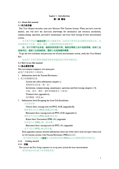
EK312A.操作手册
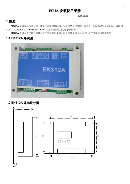
.EK312.安装使用手册-----2016.08.251 概述EK312A是得麦科技开发的1款电子膨胀阀控制器,采用过热度控制膨胀阀开度。
驱动器采用恒流驱动。
可控制ALCO、DANFOSS、SPORLAN、Carel等各种恒流驱动的电子膨胀阀。
EK312A既可与得麦科技的螺杆机控制器联机使用,也可单独使用(与其他厂家控制器组成控制系统)。
1.1 EK312A外观图1.2 EK312A外形尺寸图..1.3 EK312A 电气连接示意图EK312A电气连接示意图B-GA++-G TI DO W3W2W4AI +24G DI Com ComW1MotorB-GND A+ONOFF1234ON OFF1234O NO F FSW2JP2JP1JP3JP4JP5SW1VCCIout SW1地址1234OFF OFF 1ON OFF 2OFF ON 3ON ON4N LAC220VO N O FFSW212345V 10V举例1:12345123412312345612JP2-5设置为4-20mA输入O N O F FSW21234C V 5V 10V 举例2:JP2-5设置为0-10V输入O NO F FSW21234C V 5V 10V电子膨胀阀接线说明:ALCO膨胀阀:W4:白色W3:黑色W2:棕色W1:蓝色Danfoss膨胀阀:W4:黑色W3:白色W2:绿色W1:红色SPORLAN膨胀阀:W4:白色W3:黑色W2:绿色W1:红色Carel膨胀阀:W4:黄色W3:白色W2:棕色W1:绿色地址拔码说明:模拟输入拔码说明:报警输出启停开关电子膨胀阀24V电源输入压力传感器温度传感器通讯线运行故障通讯确认向上向下C V 0|10V0|5V 电压型电流型使用按键显示板备用注1:压力传感器接线:注2:压力传感器接线处,板内供电是24V ,如果传感器不是24V 供电,则要外接电源,之后将电源的负极接到板上的地(JP2-4)即可。
ABB传感器PFEA111-112中英文手册
hapter 1 - Introduction第一章绪论1.1About this manual1.1 关于此手册This User Manual describes your new Measure Web Tension System. When you have read the manual, you will have the necessary knowledge for mechanical and electrical installation, commissioning, operation, preventive maintenance and basic fault tracing of your measurement system.。
该手册介绍新型幅面材料的张力测量系统,阅读该手册须具备对测量系统的认知,包括机械和电气安装、调试、操作、定期检修和基本故障查寻。
注:对于不同产业来说,幅面材料所指不同。
幅面在钢铁工业中是指带钢;纺织工业是指布匹;造纸工业是指纸张;塑料工业是指塑料薄膜……To get the best reliability and precision out of your measurement system, study this User Manual first.阅读用户手册可使你的测量系统获得最佳的可靠性和精密度。
1.2How to use this manual1.2 怎么使用手册This user manual comprises two main parts.此用户手册有两个主要部分。
rmation about the Tension Electronics:1. 张力传感器的信息。
-System and safety information (chapter 1)-系统和安全信息(第一章)-Installation, commissioning, maintenance, operation and fault tracing (chapters 2-6)-安装,试车,维护,操作和故障查寻(2-6章)-Technical data (appendix A)-技术数据(附录A)rmation about Designing the Load Cell Installation:压头的安装-Vertical-force sensing load cell PFCL 301E (Appendix B)微型垂直力压头PFCL 301E (附录 B)-Horizontal-force sensing load cell PFTL 301E (Appendix C)微型水平力压头PFTL 301E (附录 C)-Radial-force Tensiometer PFRL 101 (Appendix径向张力计PFRL 101(附录D)-Horizontal-force sensing load cell PFTL 101 (Appendix水平力压头PFTL 101 (附录 E)Each appendix contains detailed information about one of the above load cell types when used in web tension systems with Tension Electronics PFEA111/112.每个附录均包括上述幅面张力系统使用到的PFEA111/112测量装置的详细信息。
世伟洛克 E 型工业压力传感器使用手册说明书
MS-CRD-PTI-ERev 2 11-08-WEL工业压力传感器用户手册 E 型E 型世伟洛克® (Swagelok)工业压力传感器可在各种各样的工业应用中提供系统压力的电子监测。
E 型传感器是被特殊设计用于满足需要防爆等级的工业应用对耐久性和性能的要求。
®引言世伟洛克工业压力传感器允许在各种工业应用中对系统压力进行电子监控。
该产品的精度为极限点校准量程的 0.5 %(最佳拟合直线量程的 0.25 %),且拥有温度补偿,能在温度波动的应用环境下确保准确性和长期稳定性。
传感器可提供各种压力连接,额定压力,压力单位和信号输出以满足众多应用需求。
■ 安全图标 ............................. 1■ 安全使用说明 ......................... 1■ 机械安装 ............................. 2■ 使用与维护 ........................... 2■ 电气安装 ............................. 2■ 接线图............................... 3■ FM 和CSA 认证 ....................... 3■ 故障排除指南 . (4)目录可能造成生命危险或严重伤害。
可能由于弹射出的部件造成生命危险或严重伤害。
可能由于高热的表面造成燃烧的危险。
注意,重要信息该产品由 CSA International 测试并鉴定。
产品在安全方面满足适用的加拿大标准。
该产品由FM Approvals 测试并鉴定。
产品在安全方面满足适用的美国标准。
警告警告警告安全图标为了正确和安全的使用,必须根据NEC 、适用的本地规范以及本说明安装、使用和维护世伟洛克 E 型 传感器。
否则,可能发生严重的人身伤害和损失。
传感器上的电子连接必须按照初始状态使用,不能添加旁路或修改。
汤姆斯勒电子PX274 PX277压力传感器说明书

B-221差压变送器带现场可选量程U 单个装置可提供多达6种可在现场选择的量程U 坚固耐用的NEMA 4 (IP65)外壳,配备外部 安装托架U 可承受高达10 psid 的 超压而不发生零点漂移U 具有短路和反向 极性保护PX274是一款坚固耐用的差压变送器,单个装置可提供多达6种可在现场选择的量程。
它含有坚固耐用的符合NEMA 4 (IP65)的防尘和防溅外壳(配备外部安装托架)。
规格激励:PX274: 12 ~ 40 Vdc PX277: 12 ~ 35 Vdc 输出:PX274: 4 ~ 20 mA (2 wire) PX277: 0 ~ 5 or 0 ~ 10 Vdc 精度: 满量程的±1.0%工作温度:-18 ~ 80°C (0 ~ 175°F)补偿温度:-4 ~ 65°C (25 ~ 150°F)热效应:0.02% FS/°C (±0.0125%/°F)耐受压力: 10 psi 介质兼容性:洁净、干燥的空气或惰性气体压力接头: 00.2" 软管倒钩接头(使用 3⁄16" 柔性管)终端: 螺钉式接线端外壳: 被釉,18 GA 钢,NEMA 4 (IP65) 级重量: 454 g (1.0 lb)配备操作手册。
订购示例: PX274-0.1DI ,电流输出压力变送器,0 ~ 0.1和-0.05 ~ 0.05 inH2O 用户可选量程。
PX277-05D5V ,电压输出压力变送器,±0.625 inH2O 和0 ~ 5 inH2O 之间用户可选多量程。
PX277-05D5V , 图片小于实际尺寸。
PX274/277 系列电流或电压输出。
智能压力传感器_开关SPS300A_B使用说明书
电源频率 消耗功率
● 环境条件 请勿在有可燃性液体或者蒸气的环境下使用,否则会损坏本机的安全性。 使用温度范围 - 20 ~+ 60℃ 使用湿度范围 0 ~ 90%RH/40℃ 容许振動 4.9m/s2 以下 (10 ~ 60Hz) 过电压类型 Category Ⅱ (IEC60364-4-443, IEC60664-1) 汚染度 Pollution degree 2 ● 机器的设置 为避免仪表操作者触摸仪表背面端子,请务必将本机安装到盘上。 4 ~ 20mA 输出的共模电压 : 对大地间的电压小于等于 33V r.m.s.、峰值小于等 于 46.7V、小于等于 DC70V。 ● 适合规格 ※ EN61010-1 、EN61326 ※ 附热带处理(型号的最后是 B,T)的产品不对应 EN61010-1。
品 名 本体 使用说明书
C -1245 CP-UM
型 号 SPS300A/B CP-UM-1425
数量 1 1
备 注 型号构成 4 页
使用说明
书
阿自倍尔
株式会社
壁挂安装套件 盘装套件
- -
1 1
仅用于壁挂安装型 的构成
本使用说明书构成如下。 第 1 章 概 要 对 SPS300A/B 的概要进行说明。 第 2 章 各部份的名称 对 SPS300A/B 的各部份的名称进行说明。 第 3 章 设置 • 安装 对 SPS300A/B 的设置 • 安装方法进行说明。 第 4 章 接 线 对 SPS300A/B 的配线进行说明。 第 5 章 操作方法 使 SPS300A/B 动作的必要的设定方法的说明。 第 6 章 故障处理 SPS300A/B 的报警代码显示及使用过程中发生故障时的故障处 理方法的说明。 第 7 章 维 护 SPS300A/B 的维护及部品更换方法的说明。 第 8 章 废 弃 废弃 SPS300A/B 的方法的说明。 第 9 章 规 格 SPS300A/B 的规格、外形尺寸及附属品 • 可选部品等的说明。
IFM传感器PN 手册
选择参数并确认参数值。
4
功能和特性
• 该压力传感器可检测系统压力。 • 并在其显示器上显示当前系统压力。 • 可根据已设定的输出配置产生两种输出信号。
模拟输出功能 (仅输出 2)
开关功能 (输出 1 和输出 2;可分别选择每种输
出的功能)
输出极性(适用于两种开关输出)
输出 1
输出 2
I:4 ... 20 mA
U:0 ... 10 V
迟滞功能/常开 (Hno)
迟滞功能/常闭 (Hnc)
CN
窗口功能/常开 (Fno)
窗口功能/常闭 (Fnc)
正极性输出 (PnP)
负极性输出 (nPn)
压力的应用类型:相对压力
订购号 PN2020 PN2021 PN2022 PN2023 PN2024
测量范围
允许的 过载压力
可调参数�������������������������������������������������������������������������������������������������������������10 技术参数�������������������������������������������������������������������������������������������������������������15 比例图�����������������������������������������������������������������������������������������������������������������16 设定范围�������������������������������������������������������������������������������������������������������������17
ECOTTER压力传感器TG-30AF说明书
显 示 分 辨 率[ F 4 ]
进入显示分辨率的设定后,将交替显示当前设置,按上、下键切换显示 分辨率。
交替显示:
分辨率切换:
1000 分辨率
按 确定保存当前设置,返回功能模式选择[F4]。
100 分辨率
省电模式设置
进入省电模式的设定后,将交替显示当前设置,按上、下键打开或关闭。 省 电 模 式 打 开 , 工 作 状 态 下 ,3 0秒 无 操 作 , 则 进 入 省 电 状 态 。
修改密码在显示解锁状态时,
同时按 键和
键进入密码修改设置。
L 显示错误
错误名称 过电流错误 残压错误 加压错误
错误显示
内容
处置方法
开 关 输 出 负 载 上 流 过8 0 m A以 上 的 电 流 。
切断电源,消除发生过电流场合的输出要因后, 再接通电源。
置 “0” 操 作 时 , 相 对 于 大 气 压 力 , 仍 有 ±3 . 5 % F . S .以 上 的 压 力。 但1秒 后 , 自 动 返 回 测 定 模 式 。 由 于 产 品 个 体 差 别 , 会 有 ±1 % F . S .置 “0” 设 定 范 围 的 不 同
主电路 主电路
N P N(1输 出 )
棕 色D C ( + )
负载
黑 色O U T
+
-
残 留 电 压1 V以 下
蓝色DC ( - )
3 产品尺寸图
P N P(1输 出 )
棕 色D C ( + )
残 留 电 压1 V以 下
+ 黑 色O U T
负载
蓝 色D C ( - )
7 功能
长按3秒 键 进 入功 能 设置 菜单, 显示[ F+数字]表示 不同的 设置 , 参照 下表选 择。
pg35压力传感器说明书中文版
pg35压力传感器说明书中文版PG35压力传感器说明书感谢您选择使用PG35压力传感器。
本说明书将为您提供有关该产品的详细信息和正确使用方法。
在使用之前,请仔细阅读本手册,并按照说明进行操作。
1. 产品概述\nPG35压力传感器是一种高精度、高可靠性的压力测量设备。
它采用先进的传感技术,能够准确测量液体或气体的压力,并将其转化为电信号输出。
2.技术规格\n- 测量范围:0-1000kPa\n- 精度等级:±0.5%FS\n- 输出信号:4-20mA\n- 工作温度范围:-20℃至80℃\n- 电源电压:24VDC3. 安装和连接\n3.1 安装\n在安装PG35压力传感器之前,请确保安装环境干燥、清洁,并远离振动和冲击。
将传感器固定在需要测量压力的位置上,确保其与被测介质充分接触。
3.2 连接\n将传感器的电源线和信号线连接到相应的设备上。
请注意,电源线和信号线应正确连接,以免损坏设备。
4. 使用方法\n4.1 开机和校准\n在使用PG35压力传感器之前,请确保电源已连接并正常工作。
按下电源开关,传感器将开始工作。
为了确保测量的准确性,建议在使用前进行校准操作。
4.2 参数设置\nPG35压力传感器具有一些可调参数,如量程、输出信号等。
您可以根据实际需求进行相应的参数设置。
具体的设置方法请参考附带的参数设置手册。
5. 注意事项\n- 请勿将传感器暴露在过高或过低的温度环境中,以免影响其性能。
\n- 请勿将传感器接触腐蚀性液体或气体,以免损坏设备。
\n- 请勿随意拆卸或修理传感器,以免造成安全隐患或损坏设备。
\n- 请定期清洁传感器表面,并检查连接线路是否正常。
6. 常见问题解答\nQ: 为什么我的PG35压力传感器测量结果不准确?\nA: 可能是由于未正确校准或参数设置不正确导致的。
请参考说明书中的校准和参数设置部分进行操作。
Q: 我可以将PG35压力传感器用于测量液体和气体吗?\nA: 是的,PG35压力传感器适用于测量液体和气体的压力。
智能电子式压力传感器说明书
36智能电子式压力传感器说明书IP68模拟量输出RM-PA1140/50-PA41-CN-V1.147面板控制与显示功能特征Output 1滞后功能/N.O.(Hno)滞后功能/N.C.(Hnc)视窗功能/N.O.(Fno)视窗功能/N.C.(Fnc)Output 2模拟输出4~20 mA(I)模拟输出0~10 V(U)从压力传感器 探测到系统当前的压力,显示系统当前压力(bar ;Psi;kgf;MPa),同时根据设置输出状态,产生两个输出信号。
滞后作用如果系统压力与预设的差不多,那么滞后现象保持在输出平稳的状态。
当系统压力增大的时候,输出端能够达到打开开关的点(SP1);当系统压力再一次减小时,输出端能够达到关闭开关的点(rP1)。
滞后调整的方法:首先打开开关的点确定好,然后根据不同的要求再重新确定。
压力 通过视窗的作用能监测到明确的可以被接受的值。
当系统在开(SP1) 和关 (rP1) 之间变化时,输出接通 (视窗作用/常开) 或不接通 (视窗作用/常闭)。
通过 SP1 和 rP1的不同可以设定视窗的宽度。
SP1为上限值,rP1为下限值。
Psp rPt滞后Hno Hnc视窗功能101049运行模式(正常工作模式)·当外部提供电压时,装置为工作模式,根据它所设置的参数来监控和开关输出。
·模拟信号的输出值与系统压力有关。
·数码管显示表明当前系统的压力,红色二极管发光表示晶体管输出时开关的状态。
()·MODE/ENTER MODE/E 键键显示模式显示参数和设置参数值当很快按下“”键时,装置为参数值可读的显示模式,装置内部的进程和输出仍然为工作模式。
·每按一下“NTER”,就会出现一个参数名称。
·当快速按“LEARN/SET”时,对应的参数值显示5秒,5秒以后装置回到工作模式。
设置模式(参数值的设定)选择确定一个参数值后(显示模式),装置就会经过一个设置模式,一直按着“LEARN/SET”键直到显示的参数值改变, 装置的内部仍为工作模式。
- 1、下载文档前请自行甄别文档内容的完整性,平台不提供额外的编辑、内容补充、找答案等附加服务。
- 2、"仅部分预览"的文档,不可在线预览部分如存在完整性等问题,可反馈申请退款(可完整预览的文档不适用该条件!)。
- 3、如文档侵犯您的权益,请联系客服反馈,我们会尽快为您处理(人工客服工作时间:9:00-18:30)。
1
3
2
8
4
6
5
7
9
1. 压力值显示∕参数值内容显示 2. 设定值显示∕设定项目显示 3. 压力单位显示 4. 第一/二组数字开关信号输出指示灯 5. 向上调整键
包装内容:压力传感器、信号线、手册 选购配件:面版安装固定件 DPA-PFKit、属固定件 DPA-FMKit
选购信息
按
按
设定显示颜色切换参考项目 按
输出二上限设定
(设定输出二为迟滞模式∕窗型模式)
按
显示代码
输出二下限设定
(设定输出二为迟滞模式∕窗型模式)
按
按
回复工厂设定值
输出二设定值
按
回附属显示设置 (设定输出二为简易模式)
按
回输出设定
初始设定
1. 单位设定:本机提供多种单位选择,包括 kPa、kgf/cm2、bar、psi、mmHg、inchHg。用户可在简易设定模式下,按
参数设定操作说明
模式切换按键操作方式:开机设定于量测模式,显示 PV/SV 值。在量测模式下按
键超过二秒,可切至简易设定模式。在量测模式
下按
键超过四秒,可切至进阶设定模式。在简易设定模式或进阶设定模式下,按
键超过二秒,可切回至量测模式。
内部选项切换按键操作方法:在量测模式、简易设定模式或进阶设定模式下,按
6. 设定功能键 7. 向下调整键 8. 电源和输出信号端子 9. 压力输入气孔
DPB 1 2 量测压力范围 3 输出型式 4 压力气孔型式
台达 DPB 系列压力传感器 01: -100kPa ~ 100kPa, 10: -100kPa ~ 1,000kPa N: NPN output;P: PNP output P:外孔 PT 1/8、内孔 M5;N:外孔 NPT 1/8、内孔 M5;G:外孔 G 1/8、内孔 M5
在简易设定模式下,按
键找到
,并按
键设定反应时间。
输出模式设定
DPB 提供三种输出模式:简易模式、迟滞模式、窗型模式。 1. 简易模式:设定压力 P。当量测压力大于 (P + dP) 值时,输出 ON。当量测压力小于 P 值时,输出为 OFF。(图一:简易模式输出图)
在量测模式下,按
键找到
(输出一)、
(输出二),按
键设定 P 值。
-4-
在进阶设定模式下,按
键找到
键一下作内部参数选择设定项目。
参数设定方法:当找到预设定或修改的参数时,利用
键更改设定。
进阶设定模式
按
超过四秒
按
超过二秒
开机 量测模式
按
超过二秒
按
超过二秒
简易设定模式
-2-
简易设定模式: 进阶设定模式:
-3-
量测模式:
简易设定模式
进阶设定模式
量测模式
输出一模式设定
附属显示设置
(变更设定值显示方式)
键找到
,
设定所需的单位。
2. 输出状态:DPB 可设定两种输出状态,N.O.(常开)和 N.C.(常闭)。用户可在简易设定模式下,按 出一、二的输出状态。
键找到
,设定输
3. 反应时间设定:当压力达到输出状态时的反应时间。如设定为 50 代表当压力达到输出状态时必须维持 50ms,输出才会动作。用户可
按
输出一上限设定 (设定输出一为迟滞模式∕窗型模式)
按
按
输出二模式设定
按
输出一、二 N.O./N.C.设定
按
输出反应时间设定
现在值颜色设定
按
单位设定
按
按
回输出一模式设定
显示更新速度设定 按
输出一下限设定 (设定输出一为迟滞模式∕窗型模式)
按
迟滞设定
输出一设定值
(设定输出一为简易模式)
系列压力传感器操作手册
非常感谢您选用台达产品,请在使用前,详细阅读本使用说明书,并将手册放置于易拿处以便参考。
注意事项
注意!电击危险! 本机为压力量测装置,请勿超出规格使用,如使用不正确的压力范围或不正确的接线,会造成人员严重伤害及其他设备损坏。 1. 安装时离开高电压及具有强高周波噪声的地方防止干扰。在以下情况会发生的场所避免使用本机: (a) 灰尘过多及有腐蚀性气体; (b) 高湿度及高辐射; (c) 震动及冲击。 2. 本机型仅适用于气体压力量测,且应避免使用于腐蚀性气体,易燃性气体或有毒气体的量测。 3. 安装或拆卸本机体时请确认电源关闭,并确认压力来源停止动作,以免造成人身和财产的伤害。 4. 安装时请使用符合压力气孔尺寸规格的部品连接,并确认完全密封,以免造成量测错误或安全性问题。 5. 上电前请确认正确的信号连接,例如电压入力和极性,过高的电压可能导致机器损坏。 6. 请使用干布清洁本机器,勿使用含有酸、碱的液体清洁。
-1-
电气规格
输入电源
压力量测
显示
输出
气孔尺寸 耐震动 耐冲击 操作环境温度 存放环境温度 操作高度 操作环境湿度
电压范围 消耗功率 压力型式
量测范围
最大耐压
量测精度 温度误差 设定显示 状态显示 显示模式 显示周期 输出组数
晶体输出
反应时间 输出误差
P N G
12 ~ 24 VDC +/- 10% 无隔离 40 mA Max. 非腐蚀性气体,相对式气压量测 (gauge type) DPB01: -100kPa ~ 100kPa DPB10: -100kPa ~ 1,000kPa DPB01: 200kPa DPB10: 1,500kPa +/- 3% 全量程 +/- 2% 全量程 双排 LCD 显示,可显示 4 位数量测值及 3.5 位数设定显示。 输出状态 LCD 显示 依据模式可设定三种颜色显示 100ms、250ms、500ms、1,000ms 内建两组 NPN 或 PNP 晶体数字输出 NPN:最大耐压 30V/100mA,导通残余电压 1.5V。 PNP:最大耐压 30V/100mA,导通残余电压 1.5V。 2ms、4ms、10ms、30ms、50ms、100ms、250ms、500ms、1,000ms、5,000ms 线性误差 < +/- 2% 全量程 外孔 PT 1/8,内孔 M5 外孔 NPT 1/8,内孔 M5 外孔 G 1/8,内孔 M5 10 ~ 500Hz,10mm 震幅,3 轴方向,持续 2 小时 最大 100m/ s2 3 轴 6 方向 各 3 次 0°C ~ +50°C -20°C ~ +65°C 低于 2,000 公尺 35% ~ 80% RH(无结露)