瑞士HUBA压力传感器–400系列
[资料]HUBA压力传感器
![[资料]HUBA压力传感器](https://img.taocdn.com/s3/m/98c53f3aec630b1c59eef8c75fbfc77da2699714.png)
HUBA压力传感器000TECK/泰克仪表代理瑞士HUBA压力传感器(HUBA511压力传感器、HUBA501压力传感器、HUBA520OEM型压力传感器、HUBA506压力传感器)HUBA压力传感器广泛应用于各种工业自控环境,涉及水利水电、铁路交通、智能建筑、生产自控、航空航天、军工、石化、油井、电力、船舶、机床、管道等众多行业000常年备货列表:000HUBA压力传感器511系列:000Huba 511.900003572 压力传感器-1-0 BAR 4-20 mA R1/4Huba 511.911003571 压力传感器0-1 BAR 4-20 mA R1/4Huba 511.911004041 压力传感器0-1 BAR 0.5-4.5VHuba 511.914001571 压力传感器0-2.5 BAR 0-5VDCHuba 511.914603571 压力传感器0-2.5 BAR 4-20 mAHuba 511.933003242 压力传感器0-40 BAR 4-20 mA 付AMPHuba 511.933003572 压力传感器0-40 BAR 4-20 mA R1/4HUBA压力传感器501系列:000Huba 510.930S03740 压力传感器0-10BAR 4-20MA,R1/4Huba 510.931S03030 压力传感器0-16 BAR 出线Huba 510.933S03540 压力传感器0-40BARHuba 510.99017 压力传感器0-40BAR 4-20mAHuba 510.99037 压力传感器0~25BAR 出线1.5M R1/4Huba 510.99069 压力传感器0-400BAR 0-10V G1/4 M12瑞士HUBA506压力传感器常用型号:(常备货)000Huba 506.930A03021W 压力传感器-1~9 BAR 4-20mAHuba 506.932A03121W 压力传感器0-25BAR 4-20MAHuba 506.932A03141W 压力传感器-1~25bar 4~20mA R1/4Huba 506.933A03141W 压力传感器-1-40BAR 4-20ma R1/4Huba 506.933A06121W 压力传感器-1~39bar 1~5VTECK/泰克仪表所销售的瑞士HUBA压力传感器为瑞士进口产品,公司备有常规型号,供货周期为即时发货。
HUBA511压力变送器
3线制
[Ohm]
0 ...5 V 8.0 ... 33 VDC>10 kOhm/< 100 nF
1 ...6 V 8.0 ... 33 VDC>10 kOhm/< 100 nF
0 ...10 V 11.4 ... 33 VD>C10 kOhm/< 100 nF
0 ...10 V 24 VAC ±15% >10 kOhm/< 100 nF
15
0…+ 6 bar
17
0…+ 10 bar
30
0…+ 16 bar
31
0…+ 25 bar
32
0…+ 40 bar
93320…+60 bar9402
0…+ 100 bar
941
2¸5
0…+ 160 bar
942
2¸5
密封材料
校准 输出信号 / 供电电源
0…+ 250 bar
0…+ 400 bar 只有FPM密封
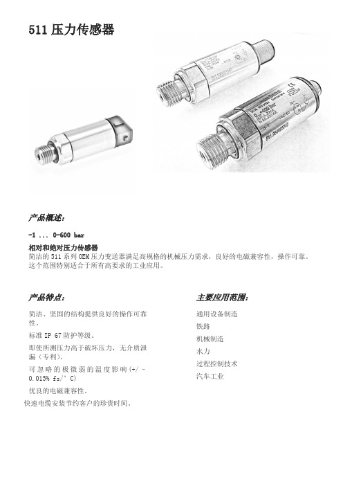
主要应用范围:
通用设备制造 铁路 机械制造 水力 过程控制技术 汽车工业
技术参数
精度:
零点漂移
max.
% fs
±0.3
满量程
max.
重复性 迟滞,线性,重复性
max.
长期稳定性 acc. DIN EN 60770
% fs
% fs % fs % fs
±0.3
0.1 ±0.3 ±1.0
TC零点 1)
max.
% fs/10K ±0.15
TC 灵敏度 1)
max.
% fs/10K ±0.15
Omega HH41 HH42 高精度温度仪表说明书
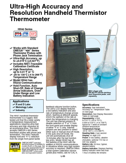
L-55feedback silicone function button. The unit’s LCD display features a low battery indication and also rate of temperature change arrows which, flashing at different speeds, inform the operator of the rate at which the temperature is changing. The unit has internal jumpers to disable selection of °F or °C from the front panel and enable display of either °F or °C only. Internal jumpers are also present to select either auto or manual shut-off mode. In the auto shut-off mode, the unit will automatically shut off 10 minutes after the last function key entry. Model HH42 has all the features of the HH41 with the addition of RS232 communications.In situations where very high system accuracy is required, OMEGA offers a total system calibration service (probe plus meter); ask for CAL-4.The HH41 handheld thermistor thermometer is a rugged, fieldtested unit that fits a wide variety of temperature measurement applications requiring ultra-high accuracy and high resolution at an economical price. The HH41 accepts OMEGA’s 400 Series thermistor probes with phone jack termination. The HH41 features display hold and °F/°C selection from the single front panel tactileU Works with Standard Omega ® “400” Series Thermistor Probes with Phone Jack Termination U Ultra-High accuracy, up to ±0.015°C (±0.027°F)U Includes NIST-Traceable Calibration Certificate U High Resolution, up to 0.01°F or °CU -20 to 130°C (-4 to 266°F) Temperature Range U model HH42 hasRS232 Communications U Hold Function, autoShut-Off, Rate of Change arrow Indicators, Over/Under Range and Low Battery IndicationHH41 shown withON-403-PP tubular stainless steel thermistor probe, sold separately.Ultra-High accuracy andResolution Handheld Thermistor ThermometerSpecificationsaccuracy: See InstrumentAccuracy vs. Temperature Table on next pageResolution: See Display Resolution Table on next page Repeatability: 0.002 to 0.01°C (-20 to 70°C);0.004 to 0.02°C (-4 to 158°F) typical for 1 week at constant ambient temperature Temperature Range: -20 to 130°C (-4 to 266°F)Reading Rate: 2 per second Display: 41⁄2 digit LCDPower: 9 Vdc battery, alkaline (included), optional 110 Vac or 220 Vac adaptorBattery Life: 20-hour, typical, alkaline batteryBattery Indicator: Displays flashing battery indicator when less than 1-hour of battery life remainsNo PointsOMEGACARE SM extendedwarranty program is available for models shown on this page. Ask your sales representative for fulldetails when placing an order.OMEGACARE SM covers parts,labor and equivalent loaners.a: ON-401-PP, general purpose probe B: ON-401-PP-V, flexible probe C: ON-403-PP, immersion probe D: ON-404-PP, glass probee: ON-405-PP, air temperature probeF: ON-408-PP, surface temperature probe g: ON-409-PP, surface temperature probe H: ON-410-PP, 1/8 NPT probe 4.5” longDisplay Resolution Temperature Unit Selection: °F/°C selectable from front panel function button, or internal jumpers Instrument accuracy* aBCDeFgH400 Series standard connectorOmega ® 400 Series thermistor probes (sold separately).A C o m p l e t eL i s t i n g o f T he r m i s t o r P r o b e s A v a i l a b l e O nl i n e。
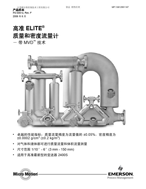
艾默生CMF系列传感器样本
kg/h
108 2180 6800 27,200 87,100 272,000 545,000
体积 (1) gal/min
0.4 10 30 120 385 1200 2400
l/h
108 2180 6800 27,200 87,100 272,000 545,000bbl/源自r550 1700 3400
高准 ELITE® 流量计是精确测量流量和密度的领导 者,ELITE 流量计可为各种过程流体提供最精确的 测量,同时具备少有的低压降。每个 ELITE 流量 计具备标准的二次外壳,接液部件可选不锈钢或镍 合金,提供各种过程连接以满足您的不同需求。
ELITE 流量计有专门用于特殊场合的设计。 CMF010 在低流量应用上显示了卓越的高性能, CMF010P 适用于高达 6000PSI (413 bar)的高 压介质,CMF400 型流量计可为大流量计量需求提 供最精确的测量结果。
±0.50% 流量 ±
⎛ ⎝
零 -------点 流------稳 量------定 值------性----⎠⎞
× 100
% 流量
±0.20% 流量 (2)
±0.25% 流量 ±
⎛ ⎝
零 -------点 流------稳 量------定 值------性----⎠⎞
× 100
% 流量
零点稳定性
质量 lb/min
kg/h
体积 (1) SCFM
Nm3/h
68 °F(20 ℃ ), 100 psi[ 磅 / 平方英寸 ] (6.8 bar) 的空气产生大约 10 psid[ 磅 / 平方英寸,压降 ] (0.68 bar) 压降时的流量
CMF010M, CMF010H CMF010P CMF025 CMF050 CMF100 CMF200 CMF300 CMF400
瑞士富巴HUBA传感器系列型号.
压力传感器 TLEE-188-503-15691 ∙压力传感器– 400系列∙压力传感器– 501系列∙压力传感器– 503系列∙压力传感器– 505系列∙压力传感器– 506系列∙压力传感器– 511系列∙压力传感器– 515系列∙压力传感器– 516系列∙压力传感器– 520系列∙压力传感器– 528系列∙压力传感器– 680系列∙压力传感器– 691系列∙压力传感器– 522系列∙压力传感器– 527系列∙差压式压力传感器– 401系列∙差压式压力传感器– 402系列∙差压式压力传感器– 403系列∙差压式压力传感器– 652系列∙差压式压力传感器– 692系列∙差压式压力传感器– 698系列∙差压式压力传感器– 699系列∙差压式压力传感器∙电子式压力开关o电子式压力开关– 521系列o电子式压力开关– 529系列o电子式压力开关- 540系列o电子式压力开关- 548系列机械式压力开关∙机械式压力开关– 604系列∙机械式压力开关– 605系列∙机械式压力开关– 610系列∙机械式压力开关– 620系列∙机械式压力开关– 625系列∙机械式压力开关– 630系列压力液位计∙压力液位计– 681系列∙压力液位计– 712系列流量传感器∙流量传感器- 200系列∙流量传感器- 210系列∙流量传感器- 230系列∙流量传感器- 235系列∙流量传感器- 236系列∙流量传感器∙压力传感器芯片o压力传感器芯片– 509系列o压力传感器芯片– 513系列o压力传感器芯片– 513 大气压系列力传感器芯片– 410系列数字式显示仪∙数字式显示仪- 800系列∙数字式显示仪- 801系列附件∙散热器。
huba差压传感器说明书
huba差压传感器说明书
瑞士富巴(瑞士HUBA)511系列压力变送器结构紧凑,在机械应力,EMC兼容性,操作可靠性方面具有极高规格,所以特别适合用于所有要求苛刻的工业应用.
此传感器使用了HUBA CONTROL近十年来发展的陶瓷技术,并使
用在数百万种应用之中,由于传感器结合采用了少有的集成电子设计,所以511系列在其温度范围下拥有很高的精度。
总之,511系列变送器具有体积小巧,优秀的性价比的特点。
可以测量气体或液体的压力
范围:相对压力-1~600Bar可选,绝对压力0-25Bar
过压:2或3倍的量程
精度:±0.3%
输出:0-5V/0-10V/4-20mA可选
瑞士HUBA 692系列压差变送器,并将其转换成标准的电流或电
压信号。
多种压力和电气连接以及外壳材料可供选择,以便适用不同的介质。
量程:0~2500Kpa
耐高温;抗温度波动;
精度:线性度、迟滞性、无机械老化现象;
重复性之和<±0.8%
无机械蠕变现象
模块系统,量体裁衣的设技术参数
系统压力:2500kPa(量程<600kPa);5000kPa(量程1000~2500)。
huba传感器
知识创造未来
huba传感器
huba传感器是德国HUBA CONTROL AG公司生产的压力传感器。
HUBA CONTROL AG是一家专业生产传感器的
公司,成立于1945年,总部位于德国。
HUBA传感器有多种型号和应用领域,包括汽车工业、医
疗设备、建筑自动化等。
它们可以测量液体和气体的压力,并将其转化为电信号输出。
HUBA传感器有很高的准确性和可靠性,可以广泛应用于
工业控制系统、仪器仪表和传感器网络等领域。
它们通常
使用标准的电气连接方式和接口,便于与其他设备进行集
成和通信。
总结来说,HUBA传感器是一种高质量的压力传感器,适
用于许多不同的应用场景。
1。
Omega 产品说明书.pdf_1719178992.496101
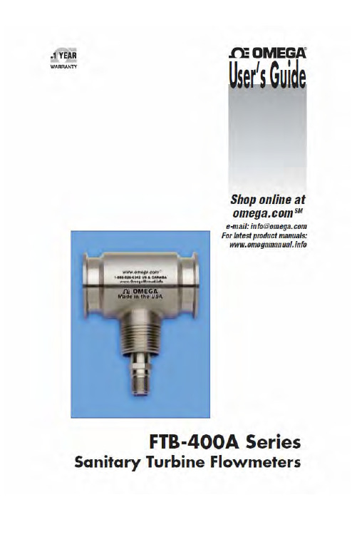
***********************Servicing North America:U.S.A. Omega Engineering, Inc.Headquarters: Toll-Free: 1-800-826-6342 (USA & Canada only)Customer Service: 1-800-622-2378 (USA & Canada only)Engineering Service: 1-800-872-9436 (USA & Canada only)Tel: (203) 359-1660 Fax: (203) 359-7700e-mail:**************For Other Locations Visit /worldwideThe information contained in this document is believed to be correct, but OMEGA accepts no liability for any errors it contains, and reserves the right to alter specifications without notice.CONTENTS1. Introduction (1)1.1 Specification (1)1.2 ModelNumber (2)2. Operation (2)2.1 Principle (3)2.2 Precautions (4)3. Installation (5)Piping (5)3.1 General3.2 Strainers/Filters (7)and Installation Kits (7)Straighteners3.3 Flow4. Maintenance (8)4.1 General (8)Procedures (8)4.2 Cleaning4.2.1 Chemical Cleaning (8)Cleaning (8)4.2.2 Steam4.3 PickupCoil Testing (10)Shooting (11)4.4 TroubleAppendix A: DrawingTypical Assembly Sanitary Flowmeter with Installation Kit (12)1.IntroductionThe following information is provided for the proper installation and maintenance of your instrument.1.1 SpecificationsLinearity: ± 0.5% of reading over linear flow rangeRepeatability:± 0.1% of readingFlow Range: 0.35 to 650 gpmTemperature Range: -450 °F to +450 °F w/ Standard MAG coilSignal Output: 10 mVrms or greater into 10K ohm load at minimum flow rate.Materials of Construction: 316/316L Dual Rated Stainless Steel Rotor 17.4 PH SSRetaining Ring 15.7 MO PH SSBearings: Hard Carbon Composite Surface Finish: 32 micro inch finish End Fitting: Tri-Grip® Sanitary Type-1-1.2 Model NumberLinear FlowRangeWater Model No.FittingsLPM GPMMaxPressureDrop(psid)Lengthmm(in)NominalK-factorPulses/GalWeightkg(lb)FTB-401A 11/2″ TRI 1.32 to13.20.35 to3.53.090.4(3.56)15,000 3 lbsFTB-402A 11/2″ TRI 2.84 to28.40.75 to7.55.090.4(3.56)8,900 3 lbsFTB-403A 11/2″ TRI 4.73 to361.25 to9.55.290.4(3.56)5,800 3 lbsFTB-404A 11/2″ TRI 6.62 to611.75 to163.090.4(3.56)5,200 3 lbsFTB-405A 11/2″ TRI 9.5 to1102.5 to295.082.5(3.25)2,200 3 lbsFTB-406A 11/2″ TRI 15 to2274 to 60 5.190.4(3.56)840 3 lbsFTB-407A 11/2″ TRI 23 to3526 to 93 4.3116.5(4.59)400 4 lbsFTB-408A 11/2″ TRI 30 to4928 to 130 3.0116.5(4.59)230 4 lbsFTB-409A 2″ TRI 57 to85215 to2253.3154(6.06)120 7 lbsFTB-410A 21/2″ TRI 95 to151425 to4004.0254(10)97 8 lbsFTB-411A 3″ TRI 151 to246040 to6504.0254(10)45 12 lbsNote: Operating pressure is limited by the TRI fitting.-2-2.Operation2.1 PrincipleThe turbine flow sensor consists of a rotor assembly which is supported on a shaft held in place by triple tube clusters and secured with locking nuts within the flowmeter housing.The rotor is free to spin on a self lubricated ceramic ball bearing. A magnetic type pickup coil is attached on the exterior of the flowmeter housing.A low mass rotor design allows for rapid dynamic response. The deflector cones eliminate downstream thrust on the rotor and allows for dynamic positioning of the rotor between deflector cones.The dynamic positioning of the low mass rotor provides wider rangeability and longer bearing life than that of conventional turbine flowmeters. Integral flow straightening tubes minimize the effects of upstream flow turbulence.As the liquid flows through the flowmeter the rotor spins at rate proportional to the volumetric liquid flowrate.Each rotor blade passing through the pickup coil generates an electrical pulse. The frequency of the pulses is proportional to flowrate. The summation of pulses represents total amount of liquid volume passed through the meter.The number of pulses generated per unit of volume is called the calibration factor or K-Factor. This calibration factor is used to calculate flowrate and total amount of flow.Material Selection and ConstructionThe housing is made of 316 stainless steel. The rotor is made of 17.4 pH stainless steel. Bearings are composite hard carbon, FDA approved.-3-Flowmeter CalibrationsThe standard calibration provided with an Omega turbine flowmeter consists of a 10-point water calibration that is traceable to NIST. Based on this water calibration, we derive an average k-factor for water for the flowmeter.The uncertainty of this calibration is typically 0.1%.The K-factor on turbine flowmeters used on liquid service is NOT density dependent.2.2 Precautions♦Do not drop the meter. Dropping the meter may result in damage to the meter housing and/or internals.♦Do not operate the meter at flowrates greater than the maximum flowrate marked on the meter. Operating at flowrates greater than the maximum flowrate may over-spin the meter. Over-spinning may result in damage to the meter.CAUTION:Avoid over-spinning the meter. Over-spinning the meter may result in damage to the meter internals and lead to meterfailure.-4-3.InstallationCAUTION:Turbine meter has to be installed with pickup coil pointing down (see Appendix A) to ensure proper cleanability.Inspect all packages for any indications of damage which may have occurred during shipment.Verify that all meter parts or auxiliary components have arrived with the shipment. Refer to the packing list/invoice for a detailed list of items included in the shipment.3.1 General PipingIt is required to install meter with a minimum straight run of pipe approximately 10 pipe diameters ahead of the inlet and 5 pipe diameters following the outlet to avoid any effect of fluid swirls.The meter housing is marked by a flow direction arrow and the inlet is marked ‘IN’ and the outlet is marked ‘OUT’. The meter must be installed in the piping in the correct orientation to ensure the most accurate operation.Install meter with adequate distance and isolation from electric motors, transformers, welding equipment and solenoids to avoid any electromagnetic interference from ambient electrical field.When it is expected that flow will be intermittent, the meter should not be mounted at a low point in the piping system. Solids which settle or congeal in the meter may affect meter performance.-5-Blocking and Bypass valves should be installed if it is necessary to do preventive maintenance on the flowmeter without shutting down the flow system. The Bypass valve can be opened before the Blocking valves are closed allowing the flow to continue while removing the turbine flowmeter for service.IMPORTANT: All flow lines should be purged prior to installing the meter. To prevent possible damage to the meter, install themeter ONLY in flow lines that are clean and free of debris. Upon initial start-up of the system a spool piece should be installed in place of the flowmeter so that purging of the system can be performed to remove all particle debris which could cause damage to the meter internals. In applications where meter flushing is required after meter service, care should be taken as to not over-spin the meter, as severe meter damage may occur.CAUTION:Avoid over-spinning the meter. Over-spinning the meter may result in damage to the meter internals and lead to meterfailure.-6--7-To maintain an accurate flow measurement it is necessary to maintain a downstream pressure sufficient to prevent flashing/cavitation. Flashing of the liquid will result in an indication of flow significantly higher than the actual flow. In order to eliminate this condition adequate downstream pressure must be maintained. The minimum required downstream pressure may be calculated using the following equation:Downstream pressure may be maintained by a downstream valve that provides the necessary downstream pressure to prevent flashing/cavitation in the metering run.3.2 Strainers/FiltersTurbine flowmeters are designed for use in a clean fluid service. However, the service fluid may carry some particulate material which would need to be removed before reaching the flowmeter. Under these conditions a strainer/filter may be required to reduce the potential hazard of fouling or damage that may be caused by foreign matter.METER SIZEMESH SIZEPARTICLE SIZE(Maximum)¼” to ½”100 .0055 5/8” to 1¼”70 .008 1½” to 3”40.015If a strainer/filter is required in the system, it should be located upstream of the flowmeter taking care that the proper minimum distance is kept between the strainer and flowmeter.3.3 Flow Straighteners and Installation KitsProper application of the Omega FTB-400A Series Flowmeter requires a minimum inlet straight pipe run of 10 pipe diameters and a minimum outlet straight pipe run of 5 pipe diameters.Installation kits for the Omega FTB-400A Series Flowmeter consist of two lengths of appropriate tubing cut to a length appropriate for the upstream and downstream straight pipe run with appropriate end fittings. Flow straightening sections may be provided within the installation kit. ()()essure xVapor essureDrop x essure Minimum Pr 25.1Pr 2Pr +=4.MaintenanceProcedures4.1 CleaningThe Omega FTB-400A Series flowmeters have been designed to allow for cleaning by commercially accepted practices. These include removing the flowmeter from the line for cleaning in an approved fluid, flushing the line with an approved cleaning solution, and steam cleaning. With all cleaning methods, care must be taken to not over-spin the meter, as severe meter damage may occur.CAUTION:Avoid over-spinning the meter. Over-spinning the meter may result in damage to the meter internals and lead to meterfailure.4.2.1 ChemicalCleaningThe flowmeters may be chemically cleaned using an approved cleaning solution by removing the meter from the service line and using a bath or by flushing the meter in place.The hard carbon composite bearing designs used have been tested and found to be compatible with the following CIP fluids manufactured by Klenzade; Mandate, AC-300, AC-101, Principle, and XY-12.Following the cleaning operation, the cleaning solution should be flushed from the meter and/or service line with potable water to remove the chemically active cleaning solution.Care should be taken to ensure that flowrates occurring during chemical cleaning do not exceed the flow capacity of the flowmeter.4.2.2Steam CleaningSteam cleaning is only recommended for meters with hard carbon composite bearings.The steam flow velocity during the cleaning should not exceed 1/3 of the maximum liquid flow capacity of the flowmeter.-8-Steam Cleaning Rates at Various Steam PressuresMeter Size 50 psigPPH175 psigPPH1100 psigPPH1125 psigPPH1VelocityFPS2RateGPM31/4 1.25 1.70 2.25 2.50 1.72 1.05 3/8 2.70 3.67 4.75 5.39 3.68 2.25 1/2 3.50 4.73 6.14 7.00 4.74 2.90 5/8 5.78 7.82 10.20 11.50 5.02 4.80 3/4 10.50 14.20 18.40 20.90 6.32 8.701 21.70 29.40 38.10 43.10 7.35 18.001¼ 33.70 45.70 59.30 67.10 7.32 28.00 1½ 47.00 63.60 82.50 93.50 7.08 39.002 81.30 110.10 142.80 162.00 6.89 67.502½ 144.60 196.00 254.00 288.00 7.84 120.003 235.00 318.00 412.60 467.00 8.85 195.00 NOTES1.PPH = Pounds Per Hour2.The velocity is expressed for a line size equal to the inlet bore of the flowmeter.3.The apparent GPM is provided since many applications have a flow rate indicatorwhich can be used to set a safe flow rate during the steam cleaning cycle.-9--10-4.3 Pickup Coil TestingTesting the MAG and MCP (RF) coils consists of measuring theresistance with an ohmmeter. Resistance measurements are to be madeonly when there is no flow through the meter.1. Measure the resistance between pin A and pin B. The resistanceshould be approximately as listed in the following table of somecommon coils.2. The resistance from any pin to the case should be greater than 1Mohm.COIL *DC RESISTANCE (Ohms) MC2PAHT15.0 ±10% MCP3A11.5 ±10% PC13-74G1800 ±10% PC13-74S1850 ±15% PC24-45G1350 ±10% PC24-45S1850 ±15% PC28-13G120 ±20% PC28-14G 180 ±20%If either resistance measurement fails, replace the pickup coil. Firmlyseat the new coil in the flowmeter and tighten the locking nut.*For specific coils not listed contact the HFC Customer Service Department for theapproximate resistance readings.4.4 TroubleShootingRefer to the following troubleshooting guide for assistance with possible meter malfunctions:TROUBLE CAUSE REMEDY Fluid will not flow ▪Meter clogged. Clean meter.through the meter ▪Line to meterblocked.Clean line to meter.Reduced flow through the meter ▪Meter partiallyclogged.Clean meter.▪Line to meterpartially blocked.Clean line to meter.Meter readings inaccurate ▪Fluid flowrate isnot within meterflow range.See “Specifications” formin and max flowrates.▪Meter drag due toimproperinstallationReplace internals.-11-DRAWINGTypical Assembly Sanitary Flowmeter with Installation Kit-12-WARRANTY/DISCLAIMEROMEGA ENGINEERING, INC. warrants this unit to be free of defects in materials and workmanship for a period of 13 months from date of purchase. OMEGA’s WARRANTY adds an additional one (1) month grace period to the normal one (1) year product warranty to cover handling and shipping time. T his ensures that OMEGA’s customers receive maximum coverage on each product.If the unit malfunctions, it must be returned to the factory for evaluation. OMEGA’s Customer Service Department will issue an Authorized Return (AR) number immediately upon phone or written request. Upon examination by OMEGA, if the unit is found to be defective, it will be repaired or replaced at no charge. OMEGA’s WARRANT Y does not apply to defects resulting from any action of the purchaser, including but not limited to mishandling, improper interfacing, operation outside of design limits, improper repair, or unauthorized modification. This WARRANTY is VOID if the unit shows evidence of having been tampered with or shows evidence of having been damaged as a result of excessive corrosion; or current, heat, moisture or vibration; improper specification; misapplication; misuse or other operating conditions outside of OMEGA’s control. Components in which wear is not warranted, include but are not limited to contact points, fuses, and triacs.OMEGA is pleased to offer suggestions on the use of its various products. However, OMEGA neither assumes responsibility for any omissions or errors nor assumes liability for any damages that result from the use of its products in accordance with information provided by OMEGA, either verbal or written. OMEGA warrants only that the parts manufactured by the company will be as specified and free of defects. OMEGA MAKES NO OTHER WARRANTIES OR REPRESENTATIONS OF ANY KIND W HATSOEVER, EXPRESSED OR IMPLIED, EXCEPT THAT OF TITLE, AND ALL IMPLIED W ARRANTIES INCLUDING ANY W ARRANTY OF MERCHANTABILITY AND FITNESS FOR A PARTICULAR PURPOSE ARE HEREBY DISCLAIMED. LIMITATION OF LIABILITY: The remedies of purchaser set forth herein are exclusive, and the total liability of OMEGA with respect to this order, whether based on contract, warranty, negligence, indemnification, strict liability or otherwise, shall not exceed the purchase price of the component upon which liability is based. In no event shall OMEGA be liable for consequential, incidental or special damages.CONDITIONS: Equipment sold by OMEGA is not intended to be used, nor shall it be used: (1) as a “Basic Component” under 10 CFR 21 (NRC), used in or with any nuclear installation or activity; or (2) in medical applications or used on humans. Should any Product(s) be used in or with any nuclear installation or activity, medical application, used on humans, or misused in any way, OMEGA assumes no responsibility as set forth in our basic WARRANTY / DISCLAIMER language, and, additionally, purchaser will indemnify OMEGA and hold OMEGA harmless from any liability or damage whatsoever arising out of the use of the Product(s) in such a manner.RETURN REQUESTS/INQUIRIESDirect all warranty and repair requests/inquiries to the OMEGA Customer Service Department. BEFORE RET URNING ANY PRODUCT (S) T O OMEGA, PURCHASER MUST OBT AIN AN AUT HORIZED RET URN (AR) NUMBER FROM OMEGA’S CUST OMER SERVICE DEPART MENT (IN ORDER T O AVOID PROCESSING DELAYS). T he assigned AR number should then be marked on the outside of the return package and on any correspondence.The purchaser is responsible for shipping charges, freight, insurance and proper packaging to prevent breakage in transit.OMEGA’s policy is to make running changes, not model changes, whenever an improvement is possible. This affords our customers the latest in technology and engineering.OMEGA is a registered trademark of OMEGA ENGINEERING, INC.© Copyright 2016 OMEGA ENGINEERING, INC. All rights reserved. This document may not be copied, photocopied, reproduced, translated, or reduced to any electronic medium or machine-readable form, in whole or in part, without the prior written consent of OMEGA ENGINEERING, INC.FOR WARRANTY RETURNS, please have the following information available BEFORE contacting OMEGA:1. Purchase Order number under which the product was PURCHASED,2. M odel and serial number of the product under warranty, and3. R epair instructions and/or specific problems relative to the product.FOR NON-WARRANTY REPAIRS, consult OMEGA for current repair charges. Have the following information available BEFORE contacting OMEGA:1. P urchase Order number to cover the COST of the repair,2. Model and serial number of the product, and 3. Repair instructions and/or specific problemsrelative to the product.Where Do I Find Everything I Need for Process Measurement and Control?OMEGA…Of Course!Shop online at SMTEMPERATUREM U Thermocouple, RTD & Thermistor Probes, Connectors, Panels & AssembliesM U Wire: Thermocouple, RTD & ThermistorM U Calibrators & Ice Point ReferencesM U Recorders, Controllers & Process MonitorsM U Infrared PyrometersPRESSURE, STRAIN AND FORCEM U Transducers & Strain GagesM U Load Cells & Pressure GagesM U Displacement TransducersM U Instrumentation & AccessoriesFLOW/LEVELM U Rotameters, Gas Mass Flowmeters & Flow ComputersM U Air Velocity IndicatorsM U Turbine/Paddlewheel SystemsM U Totalizers & Batch ControllerspH/CONDUCTIVITYM U pH Electrodes, Testers & AccessoriesM U Benchtop/Laboratory MetersM U Controllers, Calibrators, Simulators & PumpsM U Industrial pH & Conductivity EquipmentDATA ACQUISITIONM U Communications-Based Acquisition SystemsM U Data Logging SystemsM U Wireless Sensors, Transmitters, & ReceiversM U Signal ConditionersM U Data Acquisition SoftwareHEATERSM U Heating CableM U Cartridge & Strip HeatersM U Immersion & Band HeatersM U Flexible HeatersM U Laboratory HeatersENVIRONMENTALMONITORING AND CONTROLM U Metering & Control InstrumentationM U RefractometersM U Pumps & TubingM U Air, Soil & Water MonitorsM U Industrial Water & Wastewater TreatmentM U pH, Conductivity & Dissolved Oxygen InstrumentsM2124/0617。
- 1、下载文档前请自行甄别文档内容的完整性,平台不提供额外的编辑、内容补充、找答案等附加服务。
- 2、"仅部分预览"的文档,不可在线预览部分如存在完整性等问题,可反馈申请退款(可完整预览的文档不适用该条件!)。
- 3、如文档侵犯您的权益,请联系客服反馈,我们会尽快为您处理(人工客服工作时间:9:00-18:30)。
压力传感器
OEM 压力传感器– 400系列
0 ... 10 - 100 mbar
400系列压力传感器采用瑞士富巴自己开发的悬臂樑陶瓷芯片,其输出的电压信号经过温度补偿。
已被放大和线性处理的电压输出信号可直接直接适用于电气控制系统。
400系列压力传感器非常适合白色家电产品(如洗衣机,洗碗机等)的容器液位的连续测量。
有最小订货量要求
OEM 压力传感器– 501系列
-1 ... 0 - 60 bar
501系列压力传感器采用瑞士富巴自己开发的陶瓷芯片,其电流输出信号经过校准和放大。
多种压力和电气接头可供选择。
有最小订货量要求
OEM 压力传感器– 503系列
0 ... 2.5 - 25 bar
503系列压力传感器采用瑞士富巴自己开发的陶瓷芯片,其电压输出信号经过校准和放大的。
专为大批量OEM生产而设计。
有最小订货量要求
OEM 压力传感器– 505系列
0 ... 4 bar
505系列压力传感器特别适用于加热和工业循环流体中水压比的测量。
陶瓷芯片由瑞士富巴自己开发的。
输出的电压信号经过校准和放大。
专为大批量OEM生产而设计。
在壁挂炉里得到广泛的应用。
有最小订货量要求
OEM 压力传感器– 506系列
-1 ... 7 - 60 bar
506系列压力传感器采用瑞士富巴自己开发的陶瓷芯片,输出信号经过校准和放大,适用于标准化电流输出。
专为工业制冷系统而开发。
有最小订货量要求
OEM 压力传感器– 511系列
-1 ... 0 - 600 bar
OEM 压力传感器– 515系列
-1 ... 0 - 600 bar
515系列压力传感器结构紧凑,在机械应力、EMC兼容性、操作可靠性方面具有极高规格。
OEM 压力传感器– 516系列
–1 … 0 – 16 bar
516系列压力传感器应用瑞士富巴开发的陶瓷技术,最近十年来使用在数百万种应用之中。
此传感器结合采用独特的集成电路设计,在其温度范围下拥有极高的精度。
516系列压力传感器采用放大辐射输出信号技术,可以直接装配使用,无需用户调节温度或压力。
固定订货量
压力传感器– 520系列
-1 ... 9 bar / 0 ... 2.5 – 600 bar
520系列压力传感器应用了瑞士富巴开发的厚膜技术。
压力传感器芯片被焊接到压力接头上。
因而适用于制冷业包括氨水在内的所有气体和液体制冷剂。
520系列压力传感器结合采用独特的集成电路设计,在其温度范围下具有优越的电磁兼容性和极高的精度。
广泛应用于制冷,液压和气动控制等各种工业自动化技术中。
压力传感器– 528系列
–1 ... 0 – 60 bar
结构紧凑的528系列压力传感器基于瑞士富巴开发的陶瓷传感器芯片。
经过20多年的持续开发和使用,其性能和稳定性得到充分证明。
528系列的传感器使用适用于各种领域的自动控制。
压力传感器– 680系列
0 ... 0.1 - 1000 bar
680系列压力传感器采用压电电阻测量芯片,产生经过补偿校准和放大的传感器信号,适用于标准化电压或电流输出。
多种压力和电气接头可供选择。
此传感器采用不锈钢材质。
先进的模块结构系统,独特的工业设计,可满足特殊工业应用要求。
压力传感器– 691系列
-1 ... 0 - 600 bar
691系列压力传感器采用独特的陶瓷技术,最近十年来使用在数百万种应用之中。
此传感器产生经过校准和放大的传感器信号,适用于标准化电压或电流输出。
多种压力和电气接头可供选择。
压力传感器– 522系列
0 ... 2.5 – 600 bar
522系列船舶用压力传感器应用了瑞士富巴开发的厚膜不锈钢压力芯片。
压力传感器芯片被焊接到压力接头上,广泛应用于各种高要求的工业自动化技术中。
522系列船舶用压力传感器已经通过美国、法国、挪威、德国劳埃德和英国劳埃德船级社认证。
压力传感器– 527系列
0 ... 1 – 60 bar
结构紧凑的527系列压力传感器基于瑞士富巴开发的陶瓷传感器芯片。
经过20多年的持续开发和使用,其性能和稳定性得到充分证明。
527系列的传感器使用适用于各种领域的自动控制,尤其是船舶制造业,已经通过美国、法国、挪威、德国劳埃德和英国劳埃德船级社认证。