PTP503压力传感器使用说明书
503B仪器说明书

第一章概述一、用途JCQ-503B静力载荷测试仪是专为土木工程质量检测部门研制的一种智能化多功能仪器。
该仪器由主机和前端测控器组成,主机和测控器之间的通信方式为无线/有线两种方式。
该仪器配合压力传感器或力传感器、容栅式位移传感器、高压油泵、千斤顶等设备,可进行桩基础及其它地基基础的静荷载测试、土木工程试验中混凝土构件的结构性能及砌体轴压、抗剪等测试,也可用于其他有关荷载或位移检测试验。
仪器内嵌GPRS模块,可在试验过程中将测试数据实时上传至服务器,便于桩基检测机构或政府职能管理部门实现对测试现场、测试数据的有效监督、管理。
二、功能与特点1.硬件部分●仪器由主机和测控器两部分组成,两部分均为便携式一体化结构。
主机采用便携式高强度、一体化机箱。
内嵌功能强大的32位ARM微处理器并带有大容量非易失数据存储器用于存储测试数据,可实现真正的无纸化记录。
测控器测控一体化设计,可靠性高且功能强大。
●主机采用4.3寸(480*272)宽温真彩色液晶显示屏,现场可显示测试过程中的各种数据、曲线、测试状态和参数。
●主机为WINCE嵌入式操作系统,全中文界面,仪器采用按键操作,操作简洁方便。
●主机内嵌GPRS模块,用户需要时可通过GPRS网络将测试数据上传至服务器,为本单位或政府职能管理部门实行远程监管提供方便。
●测控器荷载测试通道既可连接测力传感器直接测力以适应高精度测试需要,也可连接压力传感器测量油压,通过油压自动换算成荷载值。
●测控器有4个独立的位移测试通道用于测量试桩的沉降。
●位移通道使用数字容栅式防水型位移传感器。
高精度,大量程,无时漂、温漂影响,完全满足了野外昼夜连续观测对时漂、温漂的严格要求。
●测控器内嵌油泵开关控制器,采用测试及控制一体化设计。
油泵开关控制器既可控制220V单相油泵电机,也可控制380V三相油泵电机,能实现全自动加载、补载、卸载。
●仪器可直接和用户现有的千斤顶、油泵配套使用,无需购置新的液压设备。
PAC50气动压力开关操作手册(中文版)

PAC50压力传感器: 易于集成控制
• 可选含IO-Link接口的型号, 使其能够通过连接的控制器快速、 精确地设置PAC50压力传感器的参数 • 减少停机时间, 当需要改变和更换产品时, 可通过总线更改或拷贝参数, 使用更方便。
PAC50压力传感器: 可靠且坚固耐用
• 采用防尘和防水外壳设计 (IP 65和IP 67外壳防护等级) , 是各种工业应用, 甚至是严苛 环境应用的理想之选
8016724/2014-10-23 如有更改, 恕不另行通知
PAC50 | SICK
5
PAC50 压力传感器
转变显示压力颜色
产品描述
为了更好地监测气压, 西克生产的PAC50 电子压力开关提供了一系列优势, 包括: 采用双色显示屏让您从远处就能判断压 力是否在设定范围内; 三个大的功能键 和直观的菜单导航使PAC50压力传感器 的操作更简单。 是什么让PAC50压力传感 器如此卓尔不群? 它在一个设备上就能 提供多达两个数字开关输出和一个可选 的模拟输出, 输出信号可根据控制系统的 要求轻松进行调节。 此外, 它还可以选配 IO-Link 接口, 在改变参数或更换传感器 时, 控制器或PLC能够快速且精确地将设 备参数拷贝至传感器, 从而显著降低故障 停机时间。 PAC50压力传感器的IP 65/IP 67级防水外壳使其成为各种工业应用的 理想之选。
电气安全
防护等级: III级 过压保护: 32 V DC 短路保护: QA、 Q1、 Q2与M及L+之间有短路保护 极性反接保护: L+和M之间有极性反接保护 EMC指令: 2004/108/EC, EN 61326-2-3 约40 g 防护等级为IP 65 / IP 67, 符合标准IEC 60529 (注意采用合适的连接方式) l l
805PT压力传感器用户手册说明书
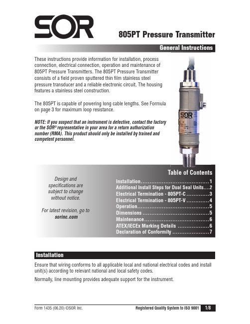
805PT Pressure TransmitterGeneral InstructionsThese instructions provide information for installation, process connection, electrical connection, operation and maintenance of 805PT Pressure Transmitters. The 805PT Pressure Transmitter consists of a field proven sputtered thin film stainless steelpressure transducer and a reliable electronic circuit. The housing features a stainless steel construction.The 805PT is capable of powering long cable lengths. See Formula on page 3 for maximum loop resistance.NOTE: If you suspect that an instrument is defective, contact the factory or the SOR ® representative in your area for a return authorization number (RMA). This product should only be installed by trained and competent personnel.Design and specifications are subject to change without notice. For latest revision, go toTable of ContentsInstallation .....2Maintenance .InstallationEnsure that wiring conforms to all applicable local and national electrical codes and install unit(s) according to relevant national and local safety codes.Normally, line mounting provides adequate support for the instrument.1st Step: Make the Process Connectionn The process connection is threaded onto a fitting within an adequately supported process piping system.o Use two open end wrenches when connecting the pressure port to a process piping system: one wrench to hold the process fitting, the other at the hex flat to tighten the pressure transmitter.p Process connection pipe or tubing may be rigid or flexible.NOTE: Do not use the 1/2” NPT(M) connection on pressures higher than 5000 psi.2nd Step: Make the Electrical Connectionn The electrical connection may be installed on an adequately supported rigid conduit system. Use suitable locknuts (not provided) when mounting the instrument to an unthreaded (knockout) hole.o Securely connect the conduit pipe or fitting by holding the flats on the electrical connection while tightening.p Electrical connection may be rigid or flexible conduit.work area is declassified. Failure to do so could result in severe personal injuryor substantial property damage.“Dual Seal” instruments. An improper installation will voidthe warranty.Vertical Installationn The figure on the right depicts the verticalinstallation profile; with the electricalleads on top. The instrument may beinstalled with the electrical leads on thebottom.o The nameplate (tag) should cover the setscrew (annunciation path). Position thenameplate slot opposite the set screw;i.e., the nameplate slot should be located180° from the set screw.Formula for determiningmaximum loop resistanceR L (MAX) = V Supply - 8V 20mAHorizontal Installationn The following figure depicts the proper horizontal installation profile; with the externalground provision and set screw (annunciation path) oriented downward.o The nameplate (tag) should not cover the set screw.PROVISIONRed (+) Black (–) Blue Green White Brown Not Used (trimmed at factory) Bare Drain Wire - Connected toEarth Ground (trimmed at factory)NOTE: An external ground screw is included for additional earth ground connection.Drawing 0190315Once the transmitter is installed and wired into a control or display loop, it is ready for use. Before applying power, check that the polarity and excitation voltage are correct.Dimensions are for reference only.Contact the factoryfor certified drawingsfor a particular model number.(First Two Numbers Indicate Year of Manufacture)TrademarkInformationThread Form InformationIdentificationDrawing 0720524For ATEX/IECEx Certified ModelsThe 805PT contains no user serviceable parts and cannot be repaired on site. It must be returned to the factory. Disassembly of the instrument by unauthorized persons will invalidate the warranty. If there is a risk of debris accumulating in the pressure port, it should be cleaned. Care and caution must be taken when cleaning the pressure port to prevent damage to the diaphragm.Special Condition for Safe UseFlamepath joints are not intended to be repairedEU Declaration of Conformity14685 West 105th Street, Lenexa, KS 66215-2003913-888-2630 • 800-676-6794 USA • 913-888-0767 FAXEngineered to Order with Off-the-Shelf SpeedProduct Manufacturer Place of Issue800 Series Electronic Pressure Transmitters SOR Inc.14685 West 105th Street II 2 G Ex db IIC T5 Gb, Ta + -40°C to IP66FM 09 ATEX 0045 Michael J. Bequette14685 West 105th Street, Lenexa, KS 66215 913-888-2630 800-676-6794 USA 。
马特罗ン PT-0 系列压力传感器连接指南说明书

PT-0-3PSI-01, PT-0-5PSI-01, PT-0-10PSI-01, PT-0-50PSI-01, PT-0-100PSI-01, PT-0-300PSI-01, PT-0-500PSI-01, PT-0-1000PSI-01, PT-0-3000PSI-01, and PT-0-5000PSI-01 Pressure TransducersWARNING – Maretron pressure transducers are not approved for use with gasoline. If you wish to use the FPM100 to monitor pressures or levels of gasoline, you must obtain a pressure transducer that isapproved for use with gasoline.InstructionsPlease follow these instructions to connect any of the PT-0-3PSI-01, PT-0-5PSI-01, PT-0-10PSI-01, PT-0-50PSI-01, PT-0-100PSI-01, PT-0-300PSI-01, PT-0-500PSI-01, PT-0-1000PSI-01, PT-0-3000PSI-01, or PT-0-5000PSI-01 pressure transducers to the NMEA 2000® network via a Maretron FPM100 Fluid Pressure Module. The wiring diagram appears in Figure 1 below. The diagram shows a connection to channel #0, but connections to other channels are similar.1. Please refer to the FPM100 User’s Guide for detailed information on selecting a mounting location for thepressure transducer.2. All Maretron pressure transducer assemblies are equipped with a ¼” NPT male threaded fitting. Install thepressure transducer to a ¼” NPT female fitting on the system or tank to be monitored with a maximumtorque of 150 in-lbs (16.95 Nm). If you are monitoring a system where pressure spikes or transients will occur, or where the pressure will exceed the maximum pressure rating of the pressure transducer, installa Pressure Snubber (PT-SNUB-01) onto the system being monitored first, then install the pressuretransducer to the female port on the pressure snubber.3. Connect the two wires of the pressure transducer to a free pressure monitoring channel. Connect the redwire from the pressure transducer to the positive (+) terminal of the channel, and connect the white wire from the pressure transducer to the negative (-) terminal of the channel. The example in Figure 1 shows the pressure transducer connected to switch channel 0 with the red wire connected to “P0+”, and thewhite wire connected to “P0-”. Pressure transducers of “Gauge” type have a small plastic vent tube in the connecting cable. Care must be taken not to kink or block this tube or allow it to be exposed tomoisture, or pressure readings will be inaccurate.4. Use a Maretron DSM250 display (firmware 1.4.7 or higher), the DSM250 viewing function of the MaretronN2KAnalyzer software, or other Maretron display product capable of configuring the FPM100 to configure the connected channel. Please refer to the FPM100 User’s Manual for configuration details.5. Supply Power to the NMEA 2000 network and verify that the pressure channel indicates a valid pressurereading.P+P-P1-P1+P2+P2-P3+P3-P4+P4-P5+P5-Figure 1 – Pressure Transducer Connection DiagramPressure Transducer Mechanical DrawingPressure Transducer SpecificationsPart Number Range Accuracy TypePT-0-3PSI-01 0 to 3 PSI (0.21 bar) ±2% Full Scale Gauge (Vent Tube)PT-0-5PSI-01 0 to 5 PSI (0.34 bar) ±2% Full Scale Gauge (Vent Tube)PT-0-10PSI-01 0 to 10 PSI (0.69 bar) ±2% Full Scale Gauge (Vent Tube)PT-0-50PSI-01 0 to 50 PSI (3.45 bar) ±1% Full Scale Gauge (Vent Tube)PT-0-100PSI-01 0 to 100 PSI (6.89 bar) ±0.5% Full Scale Gauge (Vent Tube)PT-0-300PSI-01 0 to 300 PSI (20.68 bar) ±0.5% Full Scale Gauge (Vent Tube)PT-0-500PSI-01 0 to 500 PSI (34.47 bar) ±0.5% Full Scale Absolute (No Vent Tube) PT-0-1000PSI-01 0 to 1000 PSI (68.95 bar) ±0.5% Full Scale Absolute (No Vent Tube) PT-0-3000PSI-01 0 to 3000 PSI (206.84 bar)±0.5% Full Scale Absolute (No Vent Tube) PT-0-5000PSI-01 0 to 5000 PSI (344.74 bar)±0.5% Full Scale Absolute (No Vent Tube) Specification ValueCompatible Fluids / Gases Refrigerant, Motor Oil, Diesel, Hydraulic Fluid, Brake Fluid, Water, WasteWater, Hydrogen, Nitrogen, AirOperating Temperature -40°C to 105°CStorage Temperature -40°C to 105°CProof Pressure 2.4 × Full ScaleBurst Pressure 2.4 × Full ScaleReverse Voltage Protection ± 16V over 5 MinutessteelstainlessConstruction 304LCable Length 3 feet (0.91m)Pressure/Temperature Cycles 0 to FS @ 8Hz; and –40°C to 105°C for > 1.8x10⁶ cyclesThermal Shock 105°C to –40°C, 0.5 hr soaks at Temp. (2s Transfer) for 300 cyclesVibration 100 to 2000 Hz, 20g Sinusoidal, 3 Axes for 144 hoursEMC Compatibility 10 Volts/meter per EN 61000-4-3Humidity 85°C and 90% to 95% R. H. for 250 hoursWeight 85gFor installation support, please contact:Maretron, LLP9014 N. 23rd Ave #10Phoenix, AZ 85021-7850Telephone: (+1) 866-550-9100E-mail:********************Web: 。
系列压力传感器操作手册

1. 设定参考输出状态:在量测模式下按
键超过四秒,屏幕出现
后放开,进入进阶设定模式。按
色的参考项目(详见进阶设定模式方块图)。按
键选择所要的参考项目。
键四下可看见设定颜
2. 颜色切换:在量测模式下按
键超过二秒,切入简易设定模式。按
键四下可看见设定显示颜色切换功能(详见简易设定模式
方块图)。按
键选择所要的显示颜色
注:「输出一 and 输出二」是当输出一以及输出二皆为 ON 时,才为 ON,否则皆为 OFF;「输出一 or 输出二」是当输出一以及输出二
皆为 OFF 时,才为 OFF,否则皆为 ON。
Code 代码
DPB 提供显示代码,供用户对照设定。在量测模式下按
键超过四秒,屏幕出现
下可看见显示代码(详见进阶设定模式方块图) 代码相关意义如下表:
键找到
,
设定所需的单位。
2. 输出状态:DPB 可设定两种输出状态,N.O.(常开)和 N.C.(常闭)。用户可在简易设定模式下,按 出一、二的输出状态。
键找到
,设定输
3. 反应时间设定:当压力达到输出状态时的反应时间。如设定为 50 代表当压力达到输出状态时必须维持 50ms,输出才会动作。用户可
6. 设定功能键 7. 向下调整键 8. 电源和输出信号端子 9. 压力输入气孔
DPB 1 2 量测压力范围 3 输出型式 4 压力气孔型式
台达 DPB 系列压力传感器 01: -100kPa ~ 100kPa, 10: -100kPa ~ 1,000kPa N: NPN output;P: PNP output P:外孔 PT 1/8、内孔 M5;N:外孔 NPT 1/8、内孔 M5;G:外孔 G 1/8、内孔 M5
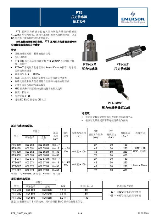
PT5系列压力传感器
72
PT5-07T 802 370 802 370M -0.8 ~ 7
27
PT5-18T PT5-30T
802 371 802 372
802 371M 802 372M
0 ~ 18 0 ~ 30
4 ~ 20 mA
-40 至 + 100
45 45
PT5-50T 802 373 802 373M 0 ~ 50
锈钢壳体保证了最佳的防腐蚀性能。预制的内埋式电气连接插座 与压力传感器之间完全密封。使PT5达到IP65的防护等级。
PT5压力传感器标定输出是一个相对的压力信号,假定周围 大气压是1 bar。当PT5处于明显高于海平面的位置时必须加以考 虑输出信号的偏移量。即每1000米海拔高度读数大约比实际值低 0.1 bar。
0 …. +40 °C -20 …. +60 °C -30 …. +80 °C
PT5-xxM (顶视图)
*) 总误差包括非线性误差、磁滞误差、重复读取误差以及温度变化所 造成的偏差和量程漂移。 注意: %FS 是传感器的全量程百分比。
PT4-Mxx 连接线只能在一个方向上与 PT5 压力传感器相连接。 图中(1)即定位键。 BN = 棕色 WH = 白色 (5) = 电子控制器;如 EC2 和 EC3 系 列控制器
各种压力范围适用于不同的制冷系统。PT5 符合欧洲 EMC 指令 并遵照 2004/108/EEC,EN61326 贴有 CE 认证标签。
PT5-07
PT5-18
PT5-30
20
PT5-50
16
输出电流 (mA)
12
8
4
0
-5
0
5
10
503说明书合订版本

CDA503系列产品使用说明-目录一、CDA503系列产品概述 (1)1.使用范围及条件 (1)2.特点 (1)3.外形尺寸 (1)4.运输、验收、存放、安装、维护 (1)二、CDA503电源单元 (1)1.主要功能及技术指标 (2)2.面板示意图 (2)1.主要功能及技术指标 (3)2.面板说明(面板功能按钮和指示灯的布置) (3)3.接线定义 (3)四、CDA503断路器控制单元 (4)1.主要功能及技术指标 (4)2.面板说明 (4)3.接线定义 (5)五、CDA503过流保护断路器控制单元 (5)1.主要技术指标 (5)2.主要功能 (5)3.面板说明 (5)4.LCD液晶显示及键盘操作 (6)5.接线定义7一、CDA503系列产品概述1.使用范围及条件海拔: 不大于2000m 环境温度: -25℃~+65℃相对湿度: 50%~95% 储存温度: -30℃~+85℃2、特点适用范围宽操作简便电机过流保护可远动控制合分闸操作抗震动、抗干扰能力强3.外形尺寸4.运输、验收、存放、安装、维护4.1 运输本产品必须包装运输, 不允许有强烈震动, 不允许倒置.4.2 验收(1)、开箱检查随机文件是否齐全....(2)、基本功能是否正常.注:随机文件..a.控制单元使用说明书一份.... b.合格证一份.4.3 存放产品应存放在室内清洁、干燥通风处, 存放时应小心, 谨防损坏.4.4 安全信息本产品为弱电设备, 但在现场安装、维护时, 附近有危险电压!本设备不能替代可见断开点, 工作时应遵循所在当地批准的安全规程;否则, 将因触高压导致严重人身伤亡.本手册并不能概括设备的安装、运行、维护等等的所有细节, 如有问题请与我公司联系.4.5安装步骤产品应安装在易操作的地方, 根据开关的位置的不同, 可安装在柱上的不同位置.安装步骤. (1)首先固定好控制单元.. (2)将外部接线接好.注: 本手册仅供参考, 如有更改, 恕不另行通知。
拓普电子旋转扭矩传感器 TQ 503 操作说明书

Pin
Description
A
Strain gauge full bridge
B
C
D
E
Rotation angle pulses
F
G
H
I
K
100% calibration
causes 100% signal
M
not connected
Top view built-in plug
Version H (special design):
Label M for Mrings
W
drive side
View W:
Size Q/R
Size R
Sense of rotation
Operating Instructions no. 1333
Page 7 / 17
4. Electrical connections
Operating Instructions no. 1333
Page 3 / 17
3. Description
3.1 Mechanical design
Torquemeters type SD comprise a rotating shaft mounted on bearings inside a housing. The shaft has a necked section - called the torsion zone - to which strain gauges are attached and connected in a full bridge circuit. Sliprings and brushes provide the link between rotor and housing with two sliprings carrying the electric power supply to the strain gauges on the rotating shaft. Two other sliprings serve to transfer the measuring signals from the rotating shaft to the stationary housing. The full bridge circuit is connected directly through the sliprings and brushes to the lead connector which is mounted on the housing of the torquemeter. In version X torquemeters an optical rotation angle measurement system is integrated. It consists of a pulse disk on the rotating shaft with 360 light-dark stripes. Two light barriers are installed into the stator. Inside the torquemeter there is a small electronics for processing of the angle pulses.
- 1、下载文档前请自行甄别文档内容的完整性,平台不提供额外的编辑、内容补充、找答案等附加服务。
- 2、"仅部分预览"的文档,不可在线预览部分如存在完整性等问题,可反馈申请退款(可完整预览的文档不适用该条件!)。
- 3、如文档侵犯您的权益,请联系客服反馈,我们会尽快为您处理(人工客服工作时间:9:00-18:30)。
油压传感器,油压压力变送器,河南压力传感器
正负压压力变送器,恒压供水压力传感器,投入式液位变送器,防雷击液位变送器,锅炉压力传感器,微差压变送器,超高温压力传感器,超高压压力传感器,平膜压力传感器,防腐蚀压力变送器,通风管道压力变送器,高温微压变送器,空压机压力变送器,空调风压变送器,PY500智能数字压力控制仪表,动静态汽车称重设备,称重测力传感器
PTP503压力传感器/变送器采用全不锈钢封焊结构,具有良好的防潮能力及优异的介质兼容性。
广泛用于工业设备、水利、化工、医疗、电力、空调、金刚石压机、冶金、车辆制动、楼宇供水等压力测量与控制。
量程:0~1~150(MPa)
综合精度:0.2%FS、0.5%FS、1.0%FS
输出信号:4~20mA(二线制)、0~5V、1~5V、0~10V(三线制)
供电电压:24DCV(9~36DCV)
介质温度:-20~85~150℃
环境温度:常温(-20~85℃)
负载电阻:电流输出型:最大800Ω;电压输出型:大于50KΩ
绝缘电阻:大于2000MΩ(100VDC
密封等级:IP65
长期稳定性能:0.1%FS/年
振动影响:在机械振动频率20Hz~1000Hz内,输出变化小于0.1%FS
电气接口(信号接口):四芯屏蔽线、四芯航空接插件、紧线螺母
机械连接(螺纹接口):1/2-20UNF、M14×1.5、M20×1.5、M22×1.5等,其它螺纹可依据客户要求设计
产品名称:PY602压力温度仪表
规格:
产品备注:数显压力温度控制仪表|智能压力温度表|佛山市博润测控仪表有限公司
产品说明
PY602数显压力-温度控制仪表
产品特点及结构:
具有整机体积小、重量轻、耗电省、功能齐全、工作可靠、使用方便灵活,配用我公司PT100-系列高温熔体压力传感器或常温压力传感器,作为高精度压力测量与控制,可广泛地使用于液压、石油、塑料、橡胶、印染、纺织等行业的压力显示和自动化控制场合,还可与其他厂家的电阻应变式压力传感器配套使用;可以设定上下限值报警,具有发光管报警指示、继电器触点输出控制外部执行机构;具有高精度的电压输出模块、电流输出模块、继电器输出控制模块以及通讯模块供用户选择
主要技术参数:
显示器:双层四位高亮度绿色和红色发光数码管
显示分辨率:0001
显示数值范围:-001~-999~0001~9999Mpa(小数点可变),温度:000.1-400.0
仪表精度:0.25%FS±1位
压力输入信号:2mV/V、3.3mV/V、4-20mA、0-5VDC、0-10DC(定货时说明)
温度输入信号:J、K、E型热电偶
采样速度:20次/秒
输出控制:与满量程信号成线性的电压或电流输出;RS232;RS485
报警范围:-001~-999~0001~9999Mpa(小数点可变)
效准指示:显示传感器满量程80%值(传感器应空载),效准指示(CAE)亮
使用温度及湿度:0-55℃,≤80%RH
电源要求:85-265VAC50Hz-60Hz
外型尺寸:96×96×100mm
开孔尺寸:92×92mm。