KHR97-B使用说明书X川南电缆坐封工具
电缆刺扎器使用说明书
电缆刺扎器使用说明书摘要仪器概述:本装置彻底解决了现场高压电缆的识别、电缆带电与否的鉴别及绝对安全的刺扎问题1.便携式结构设计,外形美观2.工作状态有超亮发光二极管指示,直观明了3.双键遥控,操作简单,双重保护开关按键关键词电缆刺扎器、射击器、电缆试扎器、电缆安全刺扎器、高压电缆安全刺扎器声明本使用说明书仅作为产品使用指导,所有陈述、信息等均不构成任何形式的担保。
服务承诺我们深信优质、系统、全面、快捷的服务是事业发展的基础。
经过多年的不断探索和进取,我们形成了“重客户、重质量"的服务理念。
以更好的产品质量,更完善的售后服务,全力打造技术领先、质量领先、服务领先的电力试验产品品牌企业。
构建良好的市场服务体系,为客户提供满意的售前、售后服务!安全要求为了避免可能发生的危险,请阅读下列安全注意事项。
本产品请使用我公司标配的附件。
防止火灾或电击危险,确保人生安全。
在使用本产品进行试验之前,请务必详细阅读产品使用说明书,按照产品规定试验环境和参数标准进行试验。
使用产品配套的保险丝。
只可使用符合本产品规定类型和额定值的保险丝。
产品输入输出端子、测试柱等均有可能带电压,试验过程中在插拔测试线、电源插座时,会产生电火花,请务必注意人身安全!请勿在仪器无前(后)盖板的情况下操作仪器/仪表。
试验前,为了防止电击,接地导体必须与真实的接地线相连,确保产品正确接地。
试验中,测试导线与带电端子连接时,请勿随意连接或断开测试导线。
试验完成后,按照操作说明关闭仪器,断开电源,将仪器按要求妥善管理。
若产品有损坏或者有故障时,切勿继续操作,请断开电源后妥善保存仪器,并与售后服务部联系,我们的专业技术人员乐于为您服务。
请勿在潮湿环境下使用仪器。
请勿在易爆环境中使用仪器(防爆产品除外)。
请保持产品表面清洁,干燥。
产品为精密仪器,在搬运中请保持向上并小心轻放。
目 录第一章:概述 (5)第二章:功能特点及技术指标 (5)2.1功能特点 (5)2.2技术指标 (5)第三章:使用方法 (6)3.1结构示意说明 (6)3.2拆装、保养说明 (7)3.2.1充电保养 (7)3.2.2拆装保养说明 (7)3.3安装说明 (7)3.4卡电缆装置安装方法 (8)3.4.1安装 (8)3.4.2拆卸 (8)3.5刺扎操作说明 (8)第四章:使用注意事项 (9)第五章:装箱清单 (10)第一章:概述多年以来,电缆运行与维护部门对电缆的刺扎,均按照行业标准DL409-91《电业安全工作规程(电力线路部分)》第234条要求,采用人工刺扎,一旦电缆识别出错,误刺扎带电电缆将造成极大的危害。
电缆弯曲工具说明书
4th International Conference on Mechatronics, Materials, Chemistry and Computer Engineering (ICMMCCE 2015)Study and Application of Cable Modeling Tools Yi Yongfei1,a, Zhu Yuanda1,a, Wang Lixia2,b, Zhang Zhen1,a, Xu DaHai1,a1Liaoning Skill Training Center2 Benxi Power Supply Company, State Grid Liaoning Electric Power Supply Co., Ltd.a ***************,b*******************Keywords: cable; bending; toolAbstract. With the rapid development of modern science and technology and the continuous advancement of industrial technology, more and more CNC bending machines have been applied in modern production and the development has become more mature. This paper introduces briefly a cable bending tool with the following features: it consists of a left and a right support plate hinged together under which handles are fixed; on the left support plate are two parallel vertical plates and under the lower plate a adjusting screw is equipped, which then pierce through the lower plate and against the upper plate; on the point where the upper plate and the adjusting screw meet a curved upper jaw and a lower jaw are set against the buckle; on the upper left corner of the right support plate a pressure roller is set.IntroductionDuring the construction process of cable installing, cables need to be bent due to environment constraints. Currently, the common cable bending method is that operators stand on the bending part of cables and then bend the cable by hand. The absence of professional tools makes it difficult to bend cables and dissatisfying wiring technics can easily damage the cable sheath and cores, bringing safety risks.This paper focuses on a new cable bending tool that consists of a left and a right support plate hinged together under which handles are fixed; on the left support plate are two parallel vertical plates and under the lower plate a adjusting screw is equipped, which then pierce through the lower plate and against the upper plate; on the point where the upper plate and the adjusting screw meet a curved upper jaw and a lower jaw are set against the buckle; on the upper left corner of the right support plate a pressure roller is set.With the rapid development of modern science and technology and the continuous advancement of industrial technology, more and more CNC bending machines have been applied in modern production and the development has become more mature. as the second largest industry to automotive industry in China, product variety and domestic market share of wire and cable industry are both more than 90%. In the world market, total output value of China's wire and cable has surpassed that of United States and China has become the world's largest wire and cable producing country. Along with the rapid development of China's wire and cable industry, number of new enterprises continues to rise and overall technical level of the industry has been greatly improved. Technological ProcessWire and cable manufacturing is completely different with production of most electromechanical products. For the general production of the latter, parts are assembled into a component and then a plurality of components are assembled into a single product, which is measured by number of units or number of pieces. Wire and cable are measured by length. All wire and cable are processed from conductors with layers of insulation, shielding, cabling and sheathing in the outside. The more complicated the structure of the product is, the more superimposed layers are.Technological FeaturesCombined production mode of large length and superimposition has overall and controlling influence on the production of wire and cable, which involves(1) Production process and equipment layoutAll equipment in the production plant must be arranged reasonably according to the required technological process of products so as to make semi-finished products at various stages flow in sequence. Equipment layout should take into consideration the balance between production efficiency and production capacity, as some equipment may have to be two or more pieces to balance the manufacturing capacity of the production line. Therefore, reasonable match-making combination and arrangement of production site have to be considered from the perspective of balance between products and production capacity.(2) Production and organization managementProduction and organization management must be scientific and rational, careful and accurate, strict and meticulous; the operator must meticulously execute according to process requirements, or any problem in the production stages will affect the smoothness of production process and thus affect the product quality and delivering. Especially for multicore cable, insufficient length of a line couple or basic unit or any problem in quality can lead to the wasting of the whole cable. Vice versa, if a unit is too long, it must be sawn and abandoned.(3) Quality managementProduction method of superimposing continuously cables of great length makes it easily to affect quality of the whole cable by a trivial and instantaneous problem in any production stages. The more inner layer the quality defects are in, the more losses will be resulted in due to failure in stopping production in time. Different with production of assembled products, wire and cable cannot be reassembled or replaced with new parts; any quality problem of any parts or production process of wire and cable can lead to almost irreversible and irreparable outcomes for the cable. Post-processing is very negative, including sawing shorter, down grading or abandoning the entire cable, as it cannot be reassembled.Quality management of wire and cable must run through the entire production process. Quality management and inspection department should tour check the entire production process; operators should check on their own operations; mutual inspection between the upper and lower production stages. These are important means to ensure product quality and improve economic efficiency of enterprises.Production technology categories and large material flowWire and cable manufacturing process involves a wide range of technology categories, from the non-ferrous metal smelting and pressure processing to chemical technologies like plastics, rubber and painting, etc.; from textile techniques like lapping and weaving of fiber materials to processing technologies like lapping of metal materials, longitudinally covering of metal strips and welding and shaping of metal materials, etc..Wire and cable manufacturing involves many kinds of materials, with many categories, varieties, specifications and a large quantity. Therefore, the using amount, spare amount, batch cycle and batches of all kinds of materials must be audited and checked. Meanwhile, decomposition of waste treatment, recycling, reuse and waste disposal should be taken as an important part of management; do good material quota management and pay attention to conservation work.In wire and cable production, from the input and output and storage of raw materials and various auxiliary materials, transferring of semi-finished products to storage and distribution of products, material flow is too much and must be distributed rationally and managed dynamically. Construction StatusesDuring the construction process of cable installing, cables need to be bent due to environment constraints. Currently, the common cable bending method is that operators stand on the bending part of cables and then bend the cable by hand. The absence of professional tools makes it difficultto bend cables and dissatisfying wiring technics can easily damage the cable sheath and cores, bringing safety risks. The new cable bending tool proposed in this paper is designed to solve the above problems as the tool can make it easy to bend wires and reduce cable damages. The tool is unique in that: it consists of a left and a right support plate hinged together under which handles are fixed; on the left support plate are two parallel vertical plates and under the lower plate a adjusting screw is equipped, which then pierce through the lower plate and against the upper plate; on the point where the upper plate and the adjusting screw meet a curved upper jaw and a lower jaw are set against the buckle; on the upper left corner of the right support plate a pressure roller is set. On the bottom of the lower jaw groove pinches are set, through which the adjusting screw penetrates and then at the penetrated end a ring is fixed. There are corresponding connecting tendons secured between the upper and lower plates and the left upright support plate. By turning the adjusting screw, one can fix the left side of a cable between the upper and lower plates, preventing it from bulk movement. Place the right side of a cable under the pressure roller and bend the cable into certain angle by pulling the two opposing handles. It is simple in structure and easy to operate with less effort, and also can bend cables flexibly by the pressure roller and prevent cables from damages caused by concentrated pressures. As shown in Fig 1Brief DescriptionFigure 1 : Equipment structure1 - left support plate, 2- right support plate, 3- handles, 4- upper vertical plate, 5-lower vertical plate, 6-connecting bars, 7- adjusting screw, 8- upper jaw, 9-lower jaw, 10- gusset, 11- ring, 12- pressure roller.ConclusionThe proposed cable bending tool consists of a upper support plate 1 and a lower support plate 2 hinged together under which handles 3 are fixed; on the left support plate 1 two parallel vertical plates 4 and 5 are fixed by connecting bars 6. Under the lower vertical plate 5 an adjusting screw 7 is equipped, which then pierce through the lower vertical plate 5 and against the upper vertical plate 4; on the point where the upper vertical plate 4 and the adjusting screw 7 meet a curved upper jaw 6 and a lower jaw 9 are set against the buckle; On the bottom of the lower jaw 9 a groove pinch 10 is set, through which the adjusting screw penetrates and then at the penetrated end a ring 11 is fixed. Inside the groove pinch 10 corresponded with ring 11, a pressure roller 12 is equipped on the upper left corner of the right support plateIn operation, first fix one side of the cable between upper jaw 8 and lower jaw 9. By turning the adjusting screw 7, one can fix the cable and press the penetrated end of the cable under the pressure roller 12. By turning the opposite handles 3, the cable can be easily bended with less effort. It is simple in structure and also can bend cables flexibly by the pressure roller and prevent cables from damages caused by concentrated pressures.Reference[1] Zhao Wei, Yang Mei, Liu Hongbin, Wu Wei, Research and development of GIS based on component. Computer and modernization 2005. 06[2] Wang Ninghui Practical manual of electrical engineer (power supply), Beijing: Machinery Industry Press, 2006[3] Hu Jianxun, Liu Kai, Liu Ting, et al. Study on the live work test of 500kv high altitude compact transmission [J]. High voltage apparatus, 2010, 46 (4):35.39.[4] Zhang Jin, Ji Shengchang, Shen Qi, et al. Study on 35 kV insulator string flashover voltage washed by charged water vapor[J]. High voltage apparatus, 2010, 46 (7):61.65.[5] Ministry of Public Security of the People’s Republic of China GB 2006, 50016---2006 Fire proof code of building design [s], China Planning Press, 2006。
电缆工具使用说明书

电缆工具使用说明书一、工具概述电缆工具是在电力工程、通信工程、建筑工程等领域中常用的装配和维修工具,用于安装、连接和维护电缆及其附件。
本使用说明书旨在帮助用户正确、安全地使用电缆工具,提高工作效率,并确保人身安全和设备完整。
二、安全须知1. 在使用电缆工具之前,请仔细阅读并理解本说明书,并遵守相关安全操作规程。
2. 使用电缆工具时,请佩戴适当的防护装备,如安全帽、防护眼镜、防护手套等。
3. 严禁未经许可擅自修改、拆解电缆工具,任何故障需由专业维修人员检修。
4. 在使用电缆工具期间,如发现任何异常情况,请立即停止使用,并及时报修。
三、常见电缆工具及使用方法1. 剥线剪剥线剪是常用的电缆工具之一,用于剥离电缆绝缘层和护套层。
使用时,将电缆放入剪刀口中,在适当的力道下剪断绝缘层,然后在剪刀刀口处用力旋转,将绝缘层剥离。
2. 铜铝焊接夹具铜铝焊接是电力工程中常见的连接方式,铜铝焊接夹具用于夹持铜铝焊接区域,确保焊接时的稳定性。
夹具的使用方法简单,将夹具固定于焊接区域,通过旋转紧固螺丝来夹紧铜铝。
3. 电缆扳手电缆扳手用于紧固和拆卸电缆连接头。
使用时,将扳手套住连接头并旋转,通过扳手的力臂原理来施加或解除扭矩。
4. 电缆剥皮钳电缆剥皮钳用于在电缆维护和故障排除过程中剥离电缆绝缘层和护套层。
使用时,将剥皮钳功能头套在电缆上,通过剥皮钳的开合来剥离绝缘层和护套层。
5. 电缆检测仪电缆检测仪用于检测电缆的绝缘状态、电压和电阻等参数。
使用时,请确保电缆检测仪的电源充足,并按照仪器使用说明正确连接电缆。
四、故障排除1. 若在使用电缆工具过程中发生电流泄漏、电缆断裂等故障,请立即停止使用,并报告维修人员进行维修。
2. 每次使用电缆工具后,请进行清洁、保养,确保工具的功能良好。
五、维修与保养1. 电缆工具的维修和保养应由专业人员进行,严禁未经训练的人员擅自进行修理。
2. 定期对电缆工具进行检查,确保工具的刀刃锐利、结构完整,并进行必要的润滑。
井下工具使用手册
Ⅰ.抽油泵一、标准抽油泵有杆泵根据深井泵的装配和在油管中的固定方式可分为管式抽油泵和杆式抽油泵。
(一)管式抽油泵1、结构特点管式泵可分为整筒泵(无衬套泵)和组合泵(衬套泵),衬套泵的外筒内装有许多节衬套组成泵筒,其与柱塞配套,而整筒泵没有衬套,柱塞与泵筒配套,整筒泵有许多优点,具有发展方向。
管式泵根据固定阀结构又可分为可打捞型泵(CYB××GL)和不可打捞型泵(CYB××G)。
详见图1-1、1-2、1-3。
整筒泵又分为厚壁泵筒泵和薄壁泵筒泵。
材质一般为铬钼铝,经氮化处理,硬度高,耐磨、耐腐蚀。
结构简单,泵筒加工难度大,但强度差。
组合泵泵筒强度高,衬套材质一般为20CrMn,经渗碳或碳氮共渗处理,硬度高、耐磨,衬套短易加工,但衬套易错位。
管式泵(打捞式)一般由泵筒总成、柱塞总成、固定阀总成、固定阀固定装置及固定阀打捞装置组成。
泵筒总成包括泵筒、泵筒接箍、加长短节、油管接箍。
泵筒是管式抽油泵最主要的零件,其两端带有螺纹,内壁经表面化学热处理(渗碳、碳氮共渗、氮化等)或电镀,然后再进行精密加工,具有良好的耐磨、耐腐蚀性能。
柱塞总成由柱塞上部出油阀罩、上下出油阀球、阀座、柱塞、柱塞下部出油阀罩组成。
固定阀总成由固定阀罩、固定阀球、固定阀座及接头组成,由锁紧装置将其固定。
固定阀锁紧装置由密封支承环、弹性芯轴、支承套组成。
弹性芯轴上端与固定阀总成的接头用螺纹连接,并将密封支承环压紧。
固定阀打捞装置由打捞体、导向套、弹簧、销子、丝锥式打捞头组成。
2、工作原理深井泵是活塞往复运动工作的,其工作冲程分为上冲程和下冲程,上冲程中,活塞在抽油杆的带动下向上移动,游动凡尔在活塞上面的液柱载荷的作用下关闭,固定凡尔在沉没压力的作用下打开,活塞让出泵筒内的容积,原油进入泵筒,这是泵的吸入过程。
同时,在井口将排出相当活塞冲程长度的一段液体。
下冲程中,抽油杆带动活塞向下移动,液柱载荷从活塞上转移到油管上,在泵内液体压力的作用下游动凡尔打开,固定阀关闭,泵内的液体排出泵筒,这是泵的排出过程。
座封工具使用步骤

坐封工具安装流程手册座封工具使用前须对产品进行检查、装配。
检查项目包括:1.检查产品的螺纹及配合面是否有碰伤、锈蚀情况;2检查0形圈外观是否有凹陷、切口、断裂等。
在对产品进行检查、装配时需准备:管钳、平口起子、勾头扳手、专用扳手、什锦锉等工具。
一、坐封工具的装配步骤为:1.将十字键套筒(连接体)放在台钳上。
2. 给挤压心轴的丝扣涂油,以其丝扣一端朝工具的上方插入十字键套筒(连接体)。
3.给活塞推杆涂油,插入挤压心轴,使其下端的槽与心轴和十字键套管(连接体)的槽对齐。
4.插入十字键。
套上键板护圈,使其贴紧十字键套筒,上紧键板护圈上的顶丝。
5.给下堵头丝扣涂油,装O圈。
6.将下堵头套在活塞推杆上向下滑,上紧丝扣和止退顶丝。
7.给活塞涂油,装上三个 O圈;将活塞装在活塞推杆上端;把销杆从活塞的侧孔拧进,穿过活塞推杆孔并上紧销杆与活塞侧孔上的丝扣。
8.给二级缸内壁上涂少许机油,将它套在活塞外边向下滑,直到与下堵头的丝扣连接并上紧。
9.给中间接头涂油,装上四个O圈;将中间接头中心孔孔大的一端朝向二级缸,上到二级缸上,拧紧丝扣;中心孔小的一端必须朝外(即小孔向油)。
至此,桥塞工具的下半部分已装配完毕,先放在一边。
10.给增压室下端丝扣涂油,装上 O圈,然后,给泄压接头涂油,装上O圈,让增压室、泄压接头、和一级缸安装在一起。
最后,使增压室朝下倒立于地上。
11.给浮动活塞涂油,装上三个 O圈。
从一级缸推入,用木棒或铝管把它桶到底与增压室相挨。
12.往一级缸里倒进干净机油,要使油面到一级缸上端面的距离准确。
13.将装好的下半部分倒置,中接头朝下接到一级缸上,将丝扣上到接头与活塞筒的缝小于一英寸以后,就可以将整个桥塞工具平放于小仪器架上,用勾头板手和管钳将丝扣上紧。
14.上紧后,由于机油的压力,活塞可能会稍向下移。
从而使十字键套筒(连接体)与下堵头之间离缝。
此缝不能大于3/8"(9.5毫米)。
如果大于3/8",则必须重新组装,并检查是否装机油太多;15.擦净增压室上边泄压阀的凹槽和放气孔,将 0圈涂油后放到凹槽底台阶上。
永久式封隔器说明书
编号:A08010490C修改号:BDGXL永久式生产封隔器使用说明书DGXL永久式封隔器简介四机赛瓦石油钻采设备有限公司DGXL永久式生产封隔器具有大内径,便于油管柱通过封隔器内孔,电缆坐封、可钻铣式。
适用于外径4 1/2"-9 5/8"的套管。
特点:•具有更大的内孔以使管柱或类似的工具穿过;•结构紧凑,易下,电缆坐封;•可坐封于任何硬度等级(包括P-110)的套管;•锯齿形锁环保证了动态坐封;•推荐用于温度177℃(350℉)、压力51Mpa(7,500PSI)的工况;•三件组合式的胶筒,金属背圈支承,整体式卡瓦避免中途坐封;•“J”形锁销接头适用于密封筒的“J”形锁销或无槽接头;•下端螺纹可连接旋出塞,NOK-OUT塞或其它附件。
注意:电缆坐封生产封隔器可用GO、BACKER和Gearhart压力坐封工具坐封, Nok-Out塞和旋塞适用于DGXL封隔器。
DGXL永久式封隔器性能参数性能参数零件号套管封隔器最大外径(英寸)最小光孔(英寸)坐封范围外径(英寸)重量(T&C)(磅)最小内径(英寸)最大内径(英寸)051-5849-001 4-1/2 11.6-16.6 3.5932.3903.7814.000051-5850-001 4-1/2 9.5-13.5 3.718 3.920 4.124051-5849-008 4-1/2 11.6-16.6 3.5932.5003.7814.000051-5850-008 4-1/2 9.5-13.5 3.718 3.920 4.124 051-5851-001 5 15.0-21.0 3.968 4.125 4.436051-5852-0015 11.5-13.04.250 4.437 4.670 5-1/2 23.0-26.0051-5848-001 4-1/2 9.5-13.5 3.7502.687*3.9204.124051-5848-006 5 15.0-21.0 3.968 4.154 4.408051-5848-0115 11.5-13.04.250 4.437 4.670 5-1/2 23.0-26.0051-5853-001 5-1/2 20.0-23.0 4.4373.0004.625 4.811051-5854-001 5-1/2 14.0-17.0 4.562 4.812 5.012 051-5855-001 5-1/2 13.0-14.0 4.750 4.976 5.124 051-5861-001 6 14.0-26.0 4.937 5.140 5.552051-5856-001 6-5/8 20.0-24.05.6874.0005.8756.094 7 32.0-38.0051-5857-001 6-5/8 17.05.8756.095 6.276 7 26.0-29.0051-5858-001 7 20.0-23.0 6.000 6.277 6.456051-5859-0017 17.0-20.06.250 6.456 6.765 7-5/8 33.7-39.0051-5860-001 7-5/8 20.0-29.7 6.625 6.875 7.125 051-5862-002 9-5/8 29.3-53.5 8.125 4.750 8.535 9.0635”DGXL永久式封隔器以下是5” 15-21#DGXL封隔器注:5” 15-21#只是5”DGXL封隔器中的一种,如需要其它型号请与我们联系。
MWBR可取式桥塞说明书
MWBR 可取式桥塞使用说明书四机赛瓦公司生产的“MWBR”电缆坐封可取式桥塞是一种封隔器型桥塞,可用电缆压力或液压座封工具坐封,用油管、钢丝绳、连续油管上提回收。
这种桥塞可用于封隔层间、油井增产或井口维修(测试、压裂和修井)等措施下。
工具坐封完成后,可以有效封隔层位,此时可从井中下入或起出其它施工工具,从而省去了压井的需要。
该桥塞的特点是将回收颈和平衡阀组合在一个多元封隔系统上,在桥塞下部装有锁环制动装置。
位于多元封隔系统下的卡瓦在牢牢地将桥塞锚定在套管上后,可以承受较大的上下压力。
并且该桥塞的坐封过程也比较简单方便,只需将电缆或液压座封工具与桥塞联接在一起后,一同送入井下预定坐封位置,点火或打压上提油管即可实现丢手。
5 1/2”桥塞释放力为:30,000 LBS(13.6吨),7”桥塞释放力为:55,000 LBS(25吨)。
产品结构、特点●结构简单、易下,电缆坐封或液压坐封;●能可靠的坐封在包括P-110以内的套管中;●推荐适用温度不高于150℃(300℉),压力不高于70Mpa(10,000PSI)的工况;●棘齿锁环保持坐封负荷,保证在压力变化下仍能可靠密封;●可用现行通用的电缆坐封工具或液压坐封工具坐封(如MAP、GO、BACKER、GEARHAT)。
下井前准备工作●检查桥塞型号是否与施工的井况相符●检查密封胶套是否有起泡、裂纹等缺陷和是否在保质期内,如果有上述缺陷或已过保质期,必须更换所有密封件●采取必要的措施保证坐封段井壁干净无垢●用适当规格的通井规通井,以保证可以正常下入工具将坐封工具与桥塞正确连接,采用油管传输把封隔器下到要求的坐封深度,下放速度不宜超过40柱/小时,注意控制下钻速度,严禁顿钻、溜钻,工具与液面接触时,应匀速缓下,过造斜点、套管悬挂、套变时也要匀速缓下。
在下井过程中,如果遇阻,应立即停止,再通过缓慢上提下放动作来活动管柱,注意遇阻力不能超过5吨。
如果尝试几次仍无法下入,取出管柱,分析原因。
神奇拓展电缆套件用户指南说明书
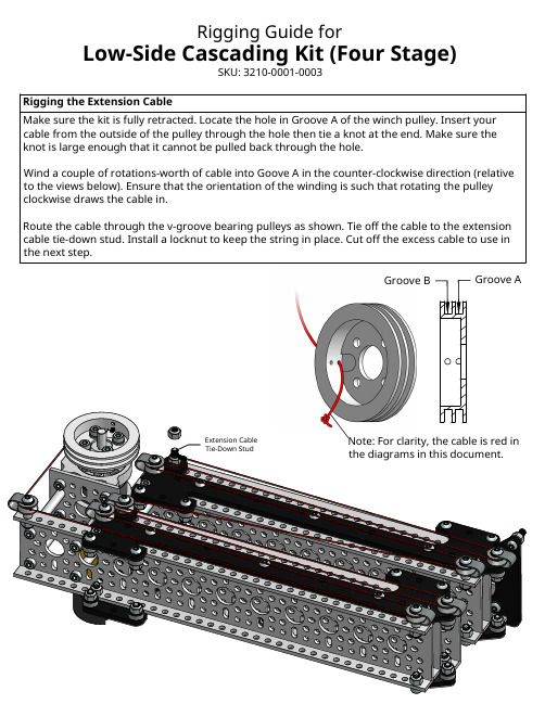
Rigging the Extension CableMake sure the kit is fully retracted. Locate the hole in Groove A of the winch pulley. Insert your cable from the outside of the pulley through the hole then tie a knot at the end. Make sure the knot is large enough that it cannot be pulled back through the hole.Wind a couple of rotations-worth of cable into Goove A in the counter-clockwise direction (relative to the views below). Ensure that the orientation of the winding is such that rotating the pulley clockwise draws the cable in.Route the cable through the v-groove bearing pulleys as shown. Tie off the cable to the extension cable tie-down stud. Install a locknut to keep the string in place. Cut off the excess cable to use in the next step.Rigging Guide forLow-Side Cascading Kit (Four Stage)SKU: 3210-0001-0003Extension CableTie-Down Stud Note: For clarity, the cable is red in the diagrams in this document.Rigging the Retraction CableFully extend the kit by rotating the winch pulley clockwise (relative to the full view below). Locate the hole in Groove B of the winch pulley. Insert a second cable through, from the outside of the pulley, and tie a large knot like you did for the extension cable.Pre-wind an extra rotation of cable into Groove B, but this time in the clockwise direction. Make sure the orientation is such that rotating the pulley counter-clockwise (relative to the full view below) draws the cable in.Locate the spring on the side of that last stage as shown. We are using the 9th hole from the end but you can select a different hole to get different levels of tautness. Tie the cable to the spring. Pro Tip: You can use a long hex key or screw to pin the spring to hole 9 while you tie the cable.Hook the loop on the other end of the spring to the spring stud and capture it with a locknut. The cable should be taut. Once you are happy with the tautness trim the excess cable.Spring Stud9th Hole。
- 1、下载文档前请自行甄别文档内容的完整性,平台不提供额外的编辑、内容补充、找答案等附加服务。
- 2、"仅部分预览"的文档,不可在线预览部分如存在完整性等问题,可反馈申请退款(可完整预览的文档不适用该条件!)。
- 3、如文档侵犯您的权益,请联系客服反馈,我们会尽快为您处理(人工客服工作时间:9:00-18:30)。
MP 格式10软盘编号密 别阶段标记SCADKHR97-B电缆桥塞座封工具使用说明书KHR97-B SM编写: 校对: 审核: 会签:标审: 批准:中国航天科技集团公司 川南机械厂会 签描 图 描 校 旧底图登记号底图登记号KHR97-B电缆桥塞座封工具使用说明书(在使用产品前请仔细阅读本说明书)1 原理电缆桥塞坐封工具用于电缆桥塞作业中,连接桥塞与电缆,地面通电,经电缆引爆坐封工具内的点火器,并点燃主装药柱,主装药柱燃烧产生的燃气压力推动坐封工具产生相对运动,实现桥塞的坐封、丢手等动作。
2 产品结构及技术参数 2.1 产品结构序号 名称 数量 1点火组件 1 2 药筒外壳 1 3 泄压组件 4O 形圈φ76.71×5.3314 5 上活塞 1 6 活塞筒 2 7 中间接头 1 8 下活塞 1 9 螺销1 10 O 形圈φ35.23×3.532 11 堵头 1 12 止动螺钉Ⅱ 1 13 止动螺钉Ⅰ 1 14 护键环 1 15 板键 1 16 活塞杆 1 17 上推力筒 1 18 活塞杆导筒11234567891011121314151718162.2 点火组件结构1-11-21-31-41-51-6大电阻桥塞点火器2.3 泄压组件结构2-12-22-32-42-52.4 技术参数 产品代号KHR97-B 联接 扣形上端点火药室 2-12UN-LH (P ) 药筒外壳 2 7/8-6Acme(B) 下端上推力筒3 1/2-6Acme(P) 活塞杆导筒 2-6Acme(P)耐压 105MPa15225psi外形尺寸 ф97mm ×1900mm ф3.82in ×74.8in序号 名称 数量 1-1 压 帽1 1-2 O 形圈φ17.6×2.62 1 1-3 O 形圈φ48.13×5.332 1-4 点火药室 1 1-5 挡圈20 1 1-6O 形圈φ57.66×5.332序号 名称 数量 2-1 泄压螺栓 1 2-2 压紧螺母 1 2-3 O 形圈φ12.8×1.781 2-4 阀座1 2-5O 形圈φ30.45×3.5313 仪器设备以及工具准备使用本产品时所需的仪器设备及工具包括:管钳、起子、专用扳手。
4 产品包装状态及使用前的检测4.1 产品包装状态4.1.1 产品出厂时点火组件、上活塞及所有O形圈均未装配,液压油在作业前注入。
4.1.2本产品采用木箱包装,每箱1套,内附产品合格证、装箱清单、产品说明书等。
4.2 使用前的检测按照《产品使用前检查记录表》的要求对产品进行检测,详细填写表内的各项内容。
5 产品装配方法5.1 坐封工具的装配5.1.1 坐封工具主体的装配5.1.1.1 将两件0形圈φ76.71×5.33(4)装入药筒外壳(2)的密封槽中,涂上润滑脂,并将药筒外壳(2)拧入活塞筒(6)。
2465.1.1.2 将三件0形圈φ76.71×5.33(4)装入上活塞(5)的密封槽中,涂上润滑脂。
用Φ20mm 的铝棒将浮动活塞推入活塞筒(6)底部(注意:有锥面的一端向内,同时必须保证活塞筒端面与浮动活塞距离为362mm)。
6455.1.1.3 将干净的10~40号机油灌入活塞筒(6),液面距活塞筒端面距离见下表。
5.1.1.4 将四件O 形圈φ0形圈φ76.71×5.33(4)装入中间接头(7)两端的密封槽中,涂上润滑脂,再将中间接头(7)拧入活塞筒(6)。
(注意:将小孔端对着油面拧入)5.1.1.5 用虎钳将上推力筒(17)夹紧,用润滑脂涂抹在活塞杆导筒(18)外表面,并将活塞杆导筒(18)插入上推力筒(17)。
(注意:坐封芯轴扣长端向外)1718温 度 距 离 200℉以下 93° 102mm 200℉~275℉ 135° 114mm 275℉~350℉ 177° 127mm 350℉~400℉ 205°140mm4675.1.1.6 插入活塞杆(16),转动活塞杆导筒(18)和活塞杆(16),使上推力筒(17)、活塞杆导筒(18)、活塞杆(16)上的键槽对齐,再将板键(15)插入键槽中。
151716185.1.1.7 将护键环(14)从右端套入上推力筒(17),并将护键环(14)上的孔和上推力筒(17)上的螺纹孔对齐,再将止动螺钉Ⅰ(13)拧入。
13141718165.1.1.8 将0形圈φ35.23×3.53(10)装入堵头(11)的内密封槽中,同时将0形圈φ76.71×5.33(4)装入堵头(11)的外密封槽中,并涂上润滑脂。
将堵头(11)穿过活塞杆(16),并拧紧在活塞杆导筒(18),同时将止动螺钉Ⅱ(12)拧入堵头(11)上的螺纹孔中。
1741011165.1.1.9 将三件0形圈φ76.71×5.33(4)装在下活塞(8)的密封槽中,涂上润滑脂,将下活塞(8)套在活塞杆(16)上,转动下活塞(8),使下活塞(8)上的螺纹孔,正对活塞杆(16)上的孔,并将螺销(9)拧入。
164895.1.1.10 将活塞筒(6)套入下活塞(8),并往堵头方向用力推活塞筒(6),将活塞筒(6)拧紧在堵头(11)上。
11865.1.1.11 按图示方向用力推活塞杆导筒(18),使护键环(14)与堵头(1)接触(注意:应无间隙)。
1814115.1.1.12 将活塞筒(6)的另一端拧紧在中间接头(7)上。
765.1.2 泄压组件的装配5.1.2.1 将0形圈φ30.45×3.53(2-5)装在阀座(2-4)上,压入药筒外壳(2)的泄压孔中。
2-42-525.1.2.2 将0形圈φ12.8×1.78装入泄压螺栓(19)的密封槽中,并旋入压紧螺母(18)。
2-12-25.1.2.3 将压紧螺母(2-2)旋入药筒外壳(1)(注意:压紧螺母为左旋螺纹),用内六方扳手旋转泄压螺栓(19)进入阀座(20),保证密封,用专用扳手,反向将压紧螺母(18)压紧在药筒外壳(1)。
2-12-22-32-42-525.2 桥塞连接组件及桥塞的装配如果选用的是哈里巴顿系列的桥塞连接组件,则按 5.2.1条进行装配;如果选用的是Baker 系列的桥塞连接组件则按照5.2.2条进行装配。
5.2.1 哈里伯顿桥塞连接组件的装配5.2.1.1 将哈里巴顿桥塞推筒及哈里巴顿桥塞内转接头分别安装到电缆桥塞坐封工具的上推力筒(17)和活塞杆导筒(18)上;并将内转接头上的止动螺钉上紧。
哈里巴顿桥塞内转接头1817哈里巴顿桥塞推筒5.2.1.2 将哈里巴顿桥塞上的释放环对准哈里巴顿桥塞内转接头后拧紧,如果哈里巴顿桥塞推筒与桥塞之间有间隙,将哈里巴顿桥塞推筒向外拧,使推筒压紧桥塞; 5.2.1.3 将推筒上的止动螺钉上紧。
5.2.2 贝克桥塞连接组件的装配5.2.2.1 将贝克桥塞连接组件中的推筒和转接头分别与电缆桥塞坐封工具的上推力筒(17)和活塞杆导筒(18)相连。
共15页 第11 页 通讯地址Add :四川省泸州市四号信箱No4 Box Luzhou Sichuan China. 电话Tel :86-0830-******* 传真Fax :86-0830-******* 转接头推筒18175.2.2.2 将Baker 桥塞连接组件中的锁紧弹簧上的拉力轴上,并将拉力轴与桥塞上的拉断螺栓相连。
桥塞锁紧弹簧拉力轴5.2.2.3 将锁紧弹簧对准转接头的缺口,旋转电缆桥塞坐封工具,使推筒压紧桥塞的上卡瓦。
拧紧桥塞转接头拉力轴锁紧弹簧推力筒5.3 点火组件的装配5.3.1 将2件0形圈φ48.13×5.33(1-3)装入点火药室(1-4)右端密封槽中,将两件0形圈φ57.66×5.33(1-6)装入点火药室(1-4)左端密封槽中,并涂上润滑脂,将1件0形圈φ17.6×2.62(1-2)装入点火药室(1-4)右端面密封槽中。
将桥塞点火器装在点火药室(1-4)右端,压住O 形圈φ17.6×2.62(1-2)。
桥塞点火器1-21-31-41-55.3.2 将压帽(1-1)拧紧在点火药室(1-4)上。
1-11-45.3.3 将传火药柱从药室座的左端装入,并将挡圈20(1-5)从左端卡入点火药室(1-4)的卡圈槽中。
1-41-5桥塞二级火药5.3.4 将组装好的点火组件装入快换接头。
快换接头点火组件5.3.5 去掉主装药上的橡胶密封盖后,将主装药装入药筒外壳(注意:有绿色传火药柱的一端朝向图示左方)。
主装药药筒外壳5.3.6 将快换接头装到电缆桥塞坐封工具的药筒外壳(2)上。
药筒外壳点火组件快换接头5.4 按以上步骤组装完成后,将快换接头与CCL 连接。
6 维护要求6.1 产品开箱后若不能及时使用,应保护好两端的螺纹不被碰伤,同时在螺纹上涂防锈油脂。
6.2 桥塞坐封作业完成后,将所有零部件拆开,清洗干净,金属件浸油。
6.3 将药筒外壳(2)中的火药残渣清理干净,并用汽油清洗干净。
6.3 重复使用时,按照第5条重新组装,并更换所有O形圈。
7 使用注意事项7.1使用时应先检查产品合格证、说明书、备件。
7.2产品组装完成后,在吊起的过程中注意保护桥塞,不要使坐封工具的重力作用在桥塞上。
7.3本产品储存期为5年,O形圈存储期为3年。
产品使用前检查记录表井号:日期:检查者(签名):产品代号KHR97-B 产品批次号产品编号井垂直深度井温井液密度检查项目检查内容检查结果(是否合格)不合格情况下的解决措施及预防措施包装箱包装箱是否完好如包装箱损坏而产品未损坏,则进行以下检查,否则停止使用该套产品开箱后产品状态产品包装是否完好请将信息反馈厂家产品合格证、装箱清单、使用说明书等是否齐全请将信息反馈厂家产品数量与装箱清单数量是否一致请将信息反馈厂家产品外观螺纹是否有明显损伤如产品螺纹不能正常连接,则停止使用该套产品产品内部是否有锈蚀或异物清除异物O形圈是否有划伤、断裂、凹陷等缺陷用备件进行更换泄压组件检查泄压组件是否完好用备件进行更换若方便,请将此表填好后寄回川南机械厂。