可分离插拔头安装手册
Cascade G Clamp 安装指南和操作手册说明书

ModelCatalog NumberParts Manualc For Technical Assistance call: 800-227-2233, Fax: 888-329-8207To Order Parts call: 888-227-2233, Fax: 888-329-0234Turnaload Clamp28G-TAL-046cascadecorporationBlankSafety DecalsPublicationsG Clamp6033701Installation Instructions6033702Operator Guide6033703Service Manual677555Driver Training Video – VHS678363Troubleshooting Video – VHS680664Servicing Cascade Cylinders – VHS679929Tool Catalog673964Literature Index Order FormRotating Frame GroupREF QTY PART NO.DESCRIPTION6237758Rotating Frame Group 116237757Faceplate226041417Frame346038208Bearing416059433Cylinder u546031224Half Ring626033537Rod End726039260Bar84212305Capscrew, M12 x 35926032650Keeper1026032659Retaining Ring 1186028433Bearing Retainer Plugu See Cylinder page for parts breakdown.REF QTY PART NO.DESCRIPTION 127769575Capscrew, M16 x 40 1316212714Hose, 360 mm 1416042392Hose, 340 mm 1516043824Hose, 305 mm 1616045078Hose, 355 mm 1716237755Cylinder u184778100Fitting, M16 199775443Capscrew, M16 x 25 2046032658Half Ring212678997Capscrew, M16 x 70 2216794217Disk Spring 232678990Nut, M1628GREF QTY PART NO.DESCRIPTION6059433Cylinder116059430Shell2217171Plug, 3316031235O-Ring u41769011Roll Pin516030920Piston Guide Ring u616032067Rod Seal u716030921Piston Seal u816032069Rod Wiper u916031229Retainer1016059432Piston/Rod Assembly6031253Service Kitu Included in Service Kit 6031253.Reference: S-21663.28GREF QTY PART NO.DESCRIPTION6237755Cylinder 116230600Shell 2217171Plug, 3316031235O-Ring u 41769011Roll Pin516030920Piston Guide Ring u 616032067Rod Seal u 716030921Piston Seal u 816032069Rod Wiper u 916031229Retainer1016059432Piston/Rod Assembly 6031253Service KituIncluded in Service Kit 6031253.Bumper Group28GREF QTY PART NO.DESCRIPTION6230575Bumper Group 116230574Bumper22768414Capscrew, M12 x 6532773842Nut, M12Reference:S-22211, S-22212.Rotator GroupREF QTY PART NO.DESCRIPTION6237769Rotator Group116237775Baseplate21775434Bearing Assembly316767596Capscrew, M12 x 4044763021Capscrew, M12 x 3057212305Capscrew, M12 x 3569214487Capscrew, M12 x 40713683822Lockwasher, M1281212308Drive Group u916605Plug1017401Grease Fitting 1116036248Sealu See Drive Group page for parts breakdown.REF QTY PART NO.DESCRIPTION 1216036287Cover Plate 133767961Capscrew, M8 x 16 142227962Eye Pin152768697Capscrew, M10 x 25 1616678991Lockwasher, M12 171670537Valve n181662187Fitting, 6-8192605761Fitting, 8-8204767611Capscrew, M10 x 40 2116237780Tube221601377Fitting, 8-8n See Valve page for parts breakdown.28GREF QTY PART NO.DESCRIPTION212308Drive Group with 2.2 c.i. Motor 16769570Capscrew, M12 x 2521676855Cover31604510Fitting, 64l670574Shim – .010” (brown)5l671757Shim – .015” (pink)6l671758Shim – .020” (yellow)72670579Bearing81670582Key91670506Pinion101775551Housing111686465Gasket121675608Worm1322705O-Ring141670549Check Valve u1546444Lockwasher, 5/16 164607059Capscrew, 5/16 NC x 1.75 1716063316Check Valve u 1816097948Drive Motor – 2.2 c.i. n 191210139Drive Motor – 2.2 c.i. nl Quantity as required.u See Valve page for parts breakdown.REF QTY PART NO.DESCRIPTION 2013014870Seal2116033892Bearing H221675609Worm Gear231670581Bearing2417214Snap Ring251643423O-Ring261775552Cover271783609Seal281783608Capscrew, M10 x 16294200882Capscrew, M8 x 20301644010Relief Fitting3144468Capscrew, 3/8 NC x .75 321775553Adapter331670575Gasket344768798Capscrew, M8 x 40354787384Lockwasher, M8364221494Washer, M8371656300Gear Box Lube – 48 oz. 381668184Sealant670578Shim Service Kit (items 4-6,11,25,38) n See Drive Motor page for parts breakdown.H For service replacement use Bearing 670580.Check ValveREF QTY PART NO.DESCRIPTION670549Check Valve Assembly H 12609453Fitting, 1022670552Spring32670551Guide427020Ball52602580Fitting, 862673989Spring71670550Body H81670553SpoolH No longer available, replaced by 6063316 Valve Assembly.REF QTY PART NO.DESCRIPTION6063316Check Valve Assembly 116063282Valve Body226038929Check Valve – PO32667516Service KitDrive Motorl Compatible with water glycol based hydraulic fluids.Cascade provides service replacement parts for the listed parts only. Due to cost, if other parts need replacement, the complete drive motor should be replaced.l Compatible with water glycol based hydraulic fluids.Cascade provides service replacement parts for the listed parts only. Due to cost, if other parts need replacement, the complete drive motor should be replaced.180° Stop ValveREF QTY PART NO.DESCRIPTION670537Stop Valve Assembly 12670541Wiper Ring22615006Back-up Ring322702O-Ring42670540Gland522841O-Ring62670539Plunger71670542Spring81670538Body91611210PinFitting GroupREF QTY PART NO.DESCRIPTION6039948Fitting Group12604511Fitting, 6-622611288Fitting, 8-6342645Cap, 6Revolving ConnectionREF QTY PART NO.DESCRIPTION6047919Revolving Connection 116047911Valve Body216027621Shaft316027694End Block413138Retaining Ring u517341Retaining Ring u63214649Shaft Seal u72684587O-Ring u82766123Capscrew, M8 x 50 u94604510Fitting, 6104778100Fitting112678376Check Valve122667516Service Kit131210266Flow Divider/Combiner 1416071170Service Kit1516056394Relief Cartridge161682170Service Kit1716033003Keeper182753159Capscrew, M6 x 10u Included in Service Kit 6047406.Turn-a-load Arm Group28GREF QTY PART NO.DESCRIPTION6237751Turn-a-load Arm Group 116237750Turn-a-load Arm226230579Arm Bar312769579Capscrew, M20 x 40Mounting GroupClass II, 0°REF QTY PART NO.DESCRIPTION215329Mounting Group 11670523Upper Hook – LH 21670524Upper Hook – RH 32675968Lower Hook 42215533Spacer 51680683Spacer68779011Capscrew, M16 x 4078678992Lockwasher, M1682219246Capscrew, M12 x 2594217637Washer, M16108684295Capscrew, M16 x 35P A R T S O R D E R I N G L O GP U R C H A S E S E R I A L R E F C A S C A D E C U S T O M E R D A T EO R D E R N U M B E RP A G E N O .Q T Y P A R T N O .P A R T N O .D E S C R I P T I O N P R I C EDo you have questions you need answered right now? Call your nearest Cascade Parts Department.Visit us online at AMERICASCascade CorporationParts Sales2501 Sheridan Ave. Springfield, OH 45505Tel: 888-CASCADE (227-2233) Fax: 888-329-0234Cascade Canada Inc.5570 Timberlea Blvd.Mississauga, OntarioCanada L4W-4M6Tel: 905-629-7777Fax: 905-629-7785Cascade do BrasilRua João Guerra, 134Macuco, Santos - SPBrasil 11015-130Tel: 55-13-2105-8800Fax: 55-13-2105-8899EUROPE-AFRICACascade Italia S.R.L. European Headquarters Via Dell’Artigianato 137030 Vago di Lavagno (VR) ItalyTel: 39-045-8989111Fax: 39-045-8989160Cascade (Africa) Pty. Ltd. PO Box 625, Isando 1600 60A Steel Road Sparton, Kempton Park South AfricaTel: 27-11-975-9240 Fax: 27-11-394-1147ASIA-PACIFICCascade Japan Ltd. 2-23, 2-Chome, Kukuchi Nishimachi Amagasaki, Hyogo Japan, 661-0978 Tel: 81-6-6420-9771 Fax: 81-6-6420-9777Cascade Korea121B 9L Namdong Ind.Complex, 691-8 Gojan-DongNamdong-KuInchon, KoreaTel: +82-32-821-2051Fax: +82-32-821-2055Cascade-XiamenNo. 668 Yangguang Rd.Xinyang Industrial ZoneHaicang, Xiamen CityFujian ProvinceP.R. China 361026Tel: 86-592-651-2500Fax: 86-592-651-2571Cascade India MaterialHandling Private LimitedNo 34, Global Trade Centre1/1 Rambaugh ColonyLal Bahadur Shastri Road,Navi Peth, Pune 411 030(Maharashtra) IndiaPhone: +91 020 2432 5490Fax: +91 020 2433 0881Cascade Australia Pty. Ltd. 1445 Ipswich Road Rocklea, QLD 4107 AustraliaTel: 1-800-227-223Fax: +61 7 3373-7333Cascade New Zealand15 Ra Ora DriveEast Tamaki, AucklandNew ZealandTel: +64-9-273-9136Fax: +64-9-273-9137Sunstream IndustriesPte. Ltd.18 Tuas South Street 5Singapore 637796Tel: +65-6795-7555Fax: +65-6863-1368c。
Green Motion EV 智能分离器充电枪安装指南说明书
Guide d’installation :Bornes pour VÉ simples ou doublesChargeurs de disjoncteur intelligent Green Motion EVChargeurs de disjoncteur intelligent Green Motion EV59,86 po11,75 po4,00 po 14,50 po11,13 po1Guide d’installation : Bornes pour VÉ simples et doublesBORNES POUR VÉ SIMPLES ET DOUBLES ContenuPRÉSENTATION DU PRODUIT . . . . . . . . . . . . . . . . . . . . . . . . . . . . . . . . . . . . . . . . . . . . . . . . . . . . . . . . . . . . . . . . . . . . . . .2Bornes pour VÉ simples ou doubles . . . . . . . . . . . . . . . . . . . . . . . . . . . . . . . . . . . . . . . . . . . . . . . . . . . . . . . . . . . . . . . . .2CONTENU DE L ’EMBALLAGE . . . . . . . . . . . . . . . . . . . . . . . . . . . . . . . . . . . . . . . . . . . . . . . . . . . . . . . . . . . . . . . . . . . . . . . .3Trousse de borne pour VÉ simple . . . . . . . . . . . . . . . . . . . . . . . . . . . . . . . . . . . . . . . . . . . . . . . . . . . . . . . . . . . . . . . . . . .3Trousse de borne pour VÉ double . . . . . . . . . . . . . . . . . . . . . . . . . . . . . . . . . . . . . . . . . . . . . . . . . . . . . . . . . . . . . . . . . . .3INSTALLATION . . . . . . . . . . . . . . . . . . . . . . . . . . . . . . . . . . . . . . . . . . . . . . . . . . . . . . . . . . . . . . . . . . . . . . . . . . . . . . . . . .4–12Renseignements sur la sécurité . . . . . . . . . . . . . . . . . . . . . . . . . . . . . . . . . . . . . . . . . . . . . . . . . . . . . . . . . . . . . . . . . . . .4Référence générale . . . . . . . . . . . . . . . . . . . . . . . . . . . . . . . . . . . . . . . . . . . . . . . . . . . . . . . . . . . . . . . . . . . . . . . . . . . . . .5Installation des bornes pour VÉ simples et doubles . . . . . . . . . . . . . . . . . . . . . . . . . . . . . . . . . . . . . . . . . . . . . . . . . .6–12• A – Couler la dalle de béton et installer les ancrages . . . . . . . . . . . . . . . . . . . . . . . . . . . . . . . . . . . . . . . . . . . . . .6–8• B – Installer le socle . . . . . . . . . . . . . . . . . . . . . . . . . . . . . . . . . . . . . . . . . . . . . . . . . . . . . . . . . . . . . . . . . . . . . . . . . .9• C – Retirer les panneaux protecteurs . . . . . . . . . . . . . . . . . . . . . . . . . . . . . . . . . . . . . . . . . . . . . . . . . . . . . . . . . . . .10• D – Installer la borne pour VÉ . . . . . . . . . . . . . . . . . . . . . . . . . . . . . . . . . . . . . . . . . . . . . . . . . . . . . . . . . . . . . . . . . .11•E – Replacer les panneaux protecteurs . . . . . . . . . . . . . . . . . . . . . . . . . . . . . . . . . . . . . . . . . . . . . . . . . . . . . . . . . .12SPÉCIFICATION S TECHN IQUES . . . . . . . . . . . . . . . . . . . . . . . . . . . . . . . . . . . . . . . . . . . . . . . . . . . . . . . . . . . . . . . . . . . . .132Chargeurs de disjoncteur intelligent Green Motion EVBORNES POUR VÉ SIMPLES ET DOUBLES Bornes pour VÉ simples ou doubles3Guide d’installation : Bornes pour VÉ simples et doublesBORNES POUR VÉ SIMPLES ET DOUBLES Contenu de l’emballageArticles requis, mais non inclus :• Matériel (c’est-à-dire boulons d’encrage ou ancrages de type T apcon) pour fixer la borne pour VÉ dans le béton – x 8• Tuyaux CPV pour faire passer les fils à travers le béton – x 3• Tige de mise à la terre • Fil • Béton • Outils* Si votre borne pour VÉ commerciale est livrée avec un étui de câble haut de gamme (GMEV32HSTR-BKR), ignorez le crochet d’enroulement du cordon fourni et installez l’étui de câble haut de gamme à la place.4Chargeurs de disjoncteur intelligent Green Motion EVBORNES POUR VÉ SIMPLES ET DOUBLES InstallationConsignes de sécurité importantesInstructions pour la mise à la terrePour un produit connecté de manière permanenteCe produit doit être connecté à un système de câblage fixe en métal mis à la terre . Sinon, un conducteur de terre de l’équipement doit être installé avec les conducteurs du circuit et connecté à la borne de terre de l’équipement ou au fil de sortie de terre sur le produit .UTILISEZ LE CODE QR SUR LA BORNE POUR VÉ POUR LA DERNIÈRE VERSION DE LA DOCUMENTATION PUISQUE L ’INFORMATION CONTENUE DANS LE PRÉSENT MANUEL EST SUJETTE AUX CHANGEMENTS .Ce produit doit être installé conformément aux exigencesdu National Electrical Code ® (NEC ®) et de tout autre code local applicable . Avant d’installer l’équipement, vérifiez les exigences en vigueur auprès de votre inspecteur électrique local et demandez-lui les informations . Si vous avez des questions ou avez besoin d’aide, contactez un entrepreneur-électricien qualifié .CONSERVEZ CES DIRECTIVES.5Guide d’installation : Bornes pour VÉ simples et doubles DéfinitionsMAEVE – Matériel d’alimentation électrique pour véhicules électriques . MAEVE est un terme général utilisé pour décrire l’ensemble de l’équipement utilisé pour alimenter un véhicule en énergie électriqueADA – Americans with Disabilities Act (loi sur les personnes ayant des incapacités aux États-Unis) .UL ® – Laboratoires des assureurs du Canada . UL est un concepteur de normes accrédité aux États-Unis et au Canada .Instructions concernant le déménagement, le transport et l’entreposageEntreposez l’équipement à l’intérieur et dans son emballage d’origine jusqu’à ce qu’il soit prêt à être installé . La température d’entreposage doit être située entre -40 °C et +60 °C . Ne soulevez, déplacez ou portez jamais l’équipement en le tenant par le cordon électrique ou le câble d’alimentation du VÉ . Un mauvais entreposage ou une manutention inappropriée risque d’endommager l’équipement .(600 mm) au-dessus du sol pour les emplacements extérieurs .Exigences de la Americans with Disabilities Act à considérer pour l’installation de recharge au travailL’ADA et la recharge au travailLa Americans with Disabilities Act (ADA) est une loi de droits civiques fédérale qui interdit la discrimination dans les lieuxpublics contre les personnes handicapées . En tant qu’employeur installant des bornes de recharge pour les véhicules électriques rechargeables (VER), aussi appelés matériel d’alimentation électrique pour véhicules électriques (MAEVE), vous devez respecter certaines directives particulières de conception pour comme l’A bornes de recharge, plusieurs études de l’industrie et des guides de planification pour les VER en contiennent . De plus, plusieurs plans élaborés dans le cadre des projets Clean Cities EV Community Readiness du département de l’Énergie des États-Unis décrivent les meilleures pratiques pour installer Meilleures pratiques pour concevoir des bornes de recharge Quand vous concevez des bornes de recharge pour VER conformes DA, tenez compte de l’accessibilité, de la facilité d’utilisation et y entrer, qu’aucun obstacle n’empêche l’accès au MAEVE ou au point de connexion sur le véhicule, et qu’il y a des passages libres et à proximité des entrées du bâtiment .Pour en savoir plus sur l’A DA, y compris les réglementationsrévisées de l’A DA 2010, veuillez visiter le site Web du département : . Si vous avez des questions spécifiques, appelez la ligne d’information sur l’DA sans frais au 800 514-0301(appel vocal) ou au 800 514-0383 (ATS) .Max. 48 po Max. 34 poMax. 10 po6Chargeurs de disjoncteur intelligent Green Motion EVBORNES POUR VÉ SIMPLES ET DOUBLES Voici les exigences minimales à respecter lors de la préparation de la dalle en béton et de l’installation de la borne pour VÉ. Veuillez noter que vous devez respecter les codes du bâtiment locaux et les directives applicables quand vous déterminez l’emplacement approprié, les dimensions et la composition de la dalle en béton.INSTALLATION DES BORNES POUR VÉ SIMPLES ET DOUBLESCouler la dalle de béton et installer les ancragesAVERTISSEMENTS ET MISES EN GARDEPour éviter les incendies, les décharges électriques et la mort, coupez l’alimentation électrique sur le disjoncteur ou le fusible et vérifiez que l’alimentation est bien coupée avant le câblage.Lisez entièrement les instructions. Si les instructionsd’installation ne sont pas suivies, des dommages matériels, des blessures corporelles, voire la mort, peuvent survenir.• Si vous avez des questions concernant l’installation, contactez votre représentant de service . Ne tentez pas d’effectuer une procédure dont vous êtes incertain .• Le câblage de la borne pour VÉ doit être conforme au National Electrical Code (NEC) et aux codes locaux .• La borne de recharge murale pour VÉ et le câblage électrique doivent être installés par un électricien conformément aux codes et aux réglementations électriques locaux .• La borne de recharge murale pour VÉ doit être connectée à unsystème de câblage fixe en métal mis à la terre . La borne pour VÉ doit être connectée à un conducteur de terre tiré à partir de la borne de mise à la terre située dans la partie inférieure de la borne pour VÉ .• Pour vous assurer que la borne de recharge murale pour VÉ et la borne pour VÉ sont installées conformément aux exigences des normes de conception accessible de la Americans with Disabilities Act (ADA), consultez le document Code of Federal Regulations, CFR 28, partie 36, sections 4 .2 et 4 .4 .• Vous devez respecter tous les codes du bâtiment locaux quand vous situez, préparez, installez et câblez la borne pour VÉ .• Installateur : Assurez-vous de laisser ces instructions avec l’utilisateur .• Utilisateur : Assurez-vous de garder ces instructions pour référence future .7Guide d’installation : Bornes pour VÉ simples et doublesBORNES POUR VÉ SIMPLES ET DOUBLES INSTALLATION DES BORNES POUR VÉ SIMPLES ET DOUBLESCouler la dalle de béton et installer les ancragesVeuillez noter qu’il est possible d’installer des boulons d’ancrage 3/8-16 en acier inoxydable, de type L ou J, avec une longueur totale minimale de 8 pouces et une longueur de filetage minimale de 2,5 pouces, dans le béton à la place des ancrages de type T apcon dans les quatre coins. Notez le type de matériel indiqué dans chaque illustration.8Chargeurs de disjoncteur intelligent Green Motion EVBORNES POUR VÉ SIMPLES ET DOUBLES INSTALLATION DES BORNES POUR VÉ SIMPLES ET DOUBLESCouler la dalle de béton et installer les ancrages9Guide d’installation : Bornes pour VÉ simples et doubles BORNES POUR VÉ SIMPLES ET DOUBLES Une fois la préparation de la dalle en béton terminée et que le béton est complètement figé et sec, effectuez lesétapes suivantes.INSTALLATION DES BORNES POUR VÉ SIMPLES ET DOUBLES Installer le socle10Chargeurs de disjoncteur intelligent Green Motion EV BORNES POUR VÉ SIMPLES ET DOUBLES INSTALLATION DES BORNES POUR VÉ SIMPLES ET DOUBLES Retirer les panneaux protecteurs11BORNES POUR VÉ SIMPLES ET DOUBLES 12BORNES POUR VÉ SIMPLES ET DOUBLES 13Guide d’installation : Bornes pour VÉ simples et doublesBORNES POUR VÉ SIMPLES ET DOUBLES Spécifications techniquesNuméro du catalogueGMEV-PED, GMEV-DPED InstallationBornes de recharge murales pour VÉ câblées à travers la borne Garantie Le Vendeur garantit que les Produits qu’il fabrique seront conformes aux spécifications applicables du Vendeur et exempts de toute défaillance due à des défauts de fabrication et de matériau pendant trois (3) ans à compter de la date d’achat originale, de l’installation du Produit ou à compter de la date d’expédition du Produit, selon la première éventualité. Dans le cas où un Produit ne serait pas conforme à la garantie ci-dessus, le Vendeur, à sa discrétion, soit (a) réparera ou remplacera le Produit défectueux, ou la pièce ou le composant défectueux, par expédition prépayée à partir des installations du Vendeur F.A.B. ou (b) créditera l’Acheteur du prix d’achat du Produit. Toutes les réclamations au titre des garanties doivent être faites par écrit. Le Vendeur exige que tous les Produits non conformes soient renvoyés aux frais du Vendeur pour être évalués, sauf indication contraire écrite du Vendeur. Cette garantie ne couvre pas les défaillances ou les dommages causés par un entreposage, une installation, un fonctionnement ou un entretien non conformes aux recommandations du Vendeur, y compris celles énoncées dans les présentes Conditions générales de vente, et aux pratiques standard de l’industrie ou causés par un accident, une mauvaise utilisation, un abus ou une négligence. Cette garantie ne couvre pas la violation de la sécurité des données ou des systèmes, y compris celle des infrastructures informatiques, des ordinateurs, des logiciels, du matériel, des bases de données, des systèmes électroniques (y compris les systèmes de gestion des bases de données) et des réseaux. La présente garantie ne couvre pas le remboursement de la main-d’œuvre, de l’accès, du retrait, de l’installation, de l’alimentation temporaire ou de toute autre dépense pouvant être engagée dans le cadre de la réparation ou du remplacement. Cette garantie ne s’applique pas aux équipements non fabriqués par le Vendeur. Le Vendeur se limite à étendre la même garantie que celle qu’il reçoit du fournisseur tiers, dans la mesure où ce tiers autorise la cession de sa garantie. Pour obtenir d’autres renseignements sur les conditions générales et les conditions de vente, veuillez consulter la Politique de vente 25-000 d’Eaton.CertificationsUL 1773 – Montants et bornes pour l’équipement de distribution Description SpécificationsEaton est une marque déposée.Toutes les marques de commerce appartiennent à leurs propriétaires respectifs.Eaton 1000 Eaton Boulevard Cleveland, OH 44122États-Unis Eaton .com© 2022 Eaton Tous droits réservés Imprimé au Canada Publication no IL191010FR Août 2022。
MENNEKES插头说明书

阿根廷
比利时
丹麦
德国
芬兰
法国
英国
意大利
加拿大
克罗地亚
荷兰挪威奥地利来自波兰俄国瑞典
瑞士
斯洛伐克
西班牙
南非
捷克
匈牙利
美国
中国
3
MENNEKES — 全世界高品质的保证
创造连接
在德国基尔兴洪登姆/萨尔兰得总部,德国东部新乡/萨克索尼和南京/中国等三个生产 基地,曼奈柯斯生产制造符合国际市场需求的接插装置。我们的产品通过地区办事处, 子公司和代理商等途径遍布全球。 拥有600多名专业人员和一流的技术,我们确信曼奈柯斯产品享誉世界。
用于全世界的接插装置
Plugs for the world
中德合资南京曼奈柯斯电器有限公司
Sino-German Joint Venture Nanjing Mennekes Electric Appliances Co., Ltd.
中文版本
Chinese Edition
2
具有曼奈柯斯标志的产品是值得信赖的产品
为了达到高质量目标,我们通过并运行了符合DIN EN ISO 9001:2000标准的国际质量管理体系。作为以出 口为导向的企业,曼奈柯斯还获得了以下相关领域的国际机构的产品认证。
DMT
国际认证证书
曼奈柯斯的接插装置符合相关国家和国际标准。由于一些特殊的国家标准,并不是每一个产品都能 接受国际认证。
4
保持连接
德国东部新乡工厂
南京工厂
只有通过严格检验的产品,才能具有曼奈柯斯的名称。 我们的产品经过试验室里的剧冷、高热、防尘和浸水等在极端条件下的反复测试之 后,根据国际标准,获得了权威机构的认证。
5
VPX安装使用说明

VPX系列连接器使用指导书VPX系列连接器不具有防舀挖设计结构,但通过可识别的导销、导套引导定位可以在使用过程中进行盲插使用。
VPX系列连接器插座装到背板上方可与插头进行对插,否则插座和插头对插时会将插座绝缘体部件顶出。
发生此类事情后,将绝缘体部件按原来位置重新装入插座壳体即可。
一、高速部分及连接器导向键的装配【插头连接器使用】第一步:观察结构拿到VPX系列插头连接器时首先观察产品的结构特点,确定插头与印制板子板配合有几个关键点:(1)插头连接器壳体两端的螺纹孔和导向柱;(2)插头连接器模块上面的定位针;(3)插头连接器模块上的鱼眼式接触件。
根据键位要求,先将散件包装的导套和挡圈装配到连接器上。
如图1所示。
图1 产品结构示意图导销导套装配要点:3U 连接器有2对导销导套,6U 连接器有3对导销导套,每对导销导套有8个键位,可以防止相同型号的连接器错装,即每个型号的3U 连接器有64种不同的键位组合形式,每个型号的6U 连接器有512种不同的键位组合形式,用以防止错装。
每对导销导套有8个键位,使用时需要导销、导套的键位一致,才能保证连接器的正常对插。
所以导销导套的安装对连接器的正常插合有很大的影响,下面就介绍下导套的安装方法及注意事项,导销安装在插座安装说明中介绍。
1.导套的安装导套安装在插头连接器上,利用弹性挡圈进行固定,如图所示安装步骤:1)首先确定连接器的键位;2)键位确定后,将导套装入插头连接器的导套孔内,安装到位。
注意导套的八方结构与壳体的八方结构相适配;如下图所示:3)导套安装到位后,将弹性挡圈装入壳体的环形挡圈槽中,装入时注意弹性挡圈的开口与壳体的开槽开口方向一致。
装配步骤如下:a)将弹性挡圈的一端放入壳体中,开口与壳体槽口一致; b)稍用力将弹性挡圈大部分装入壳体; c)借用工具将弹性挡圈压进壳体环形槽中;d)弹性挡圈压入后,由于变形,可能会出现两端交错现象,这时调整下弹性挡圈位置即可(利用细小的镊子尖端或者其他可以插入弹性挡圈两端孔内的小工具稍微转动下挡圈即可)至此,导套装配完毕,若要更换导套的键位,利用工具将弹性挡圈取出,更换键位后按照以上安装步骤使用备用的弹性挡圈安装即可,取出的弹性挡圈不再使用。
简述快插式气动管接头的安装与拔出方法-概述说明以及解释
简述快插式气动管接头的安装与拔出方法-概述说明以及解释1.引言1.1 概述快插式气动管接头是一种常用的连接管道的装置,它能够快速、简便地连接和断开管道,节省了安装和拆卸的时间和劳力。
该接头具有可靠的密封性能和耐压能力,广泛应用于各种气动系统中。
本文主要介绍了快插式气动管接头的安装和拔出方法。
在安装方面,需要做好准备工作,包括检查管道的光洁度和平整度,确保接头的顺利安装。
然后按照一定的步骤进行安装,确保每个连接都紧密牢固,不漏气,不松动。
而在拔出方面,也需要做好准备工作,例如关闭气源,排空管道内的气体等。
然后按照规定的步骤进行拔出,避免对管道和接头造成损坏。
通过本文的介绍,读者可以了解到快插式气动管接头的基本原理和其安装、拔出的方法,对使用和操作这种接头具有一定的指导意义。
另外,本文还对快插式气动管接头的应用前景进行了展望,指出了其在未来气动系统中的重要作用和广阔的发展空间。
总之,快插式气动管接头的安装和拔出方法的研究对于提高气动系统的效率和可靠性具有重要意义。
文章结构部分的内容可以写成如下形式:1.2 文章结构本文主要包括三个部分:引言、正文和结论。
引言部分首先概述了快插式气动管接头的安装与拔出方法,说明了本文的目的是为了介绍这种管接头的安装与拔出过程。
接着描述了文章的结构,即引言、正文和结论。
正文部分是本文的核心内容,主要包括两个方面:快插式气动管接头的基本原理和安装与拔出方法。
首先,通过介绍快插式气动管接头的基本原理,读者可以了解其工作原理和特点。
然后,详细介绍了安装与拔出方法,包括准备工作和具体的步骤。
通过这部分内容,读者可以掌握正确、安全地使用快插式气动管接头的技巧和方法。
结论部分对全文进行总结,并展望了快插式气动管接头的应用前景。
总结部分回顾了快插式气动管接头的基本原理和安装与拔出方法,并强调了其重要性和实用性。
应用前景部分展示了快插式气动管接头在工业生产中的潜在应用领域,为读者提供了进一步了解和研究的方向。
3M插拔头说明书
注:如应用于三芯电缆,需另配3M冷缩式插拔终端密封组件RKT系列
RKT 密封组件
➢ 应用: 电缆三叉密封 ➢ 技术: 冷缩式密封配套组件 ➢ 特点: 安装简便,无需动火
3M 3M 3M 3M 3M 3M 3M 3M
38
39
630 Amp China Tee 6/10(12) kV; 8.7/15(17.5) kV; 18/30(36) kV 最大电缆截面为400mm2 配有适配器 全套三芯冷缩 RKT部件
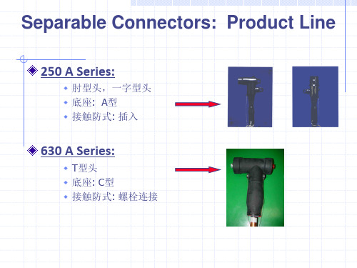
欧式可分离式连接器
IEC60502; CELENEC HD629.1
250 A Distribution circuits : 不带电插拔 (肘型头)
3EA 3EA 1EA 1/3RL 1RL 1EA 各1RL
China Tee 选型表(III)
型号
93-EE905-4/35-CN 93-EE905-4-CN 93-EE915-4-CN 93-EE925-4-CN 93-EE935-4-CN 93-EE945-4-CN 93-EE955-4-CN 93-EE965-4-CN 93-EE975-4-CN 93-EE985-4-CN
硅橡胶材料
无氯、无烟
弹性
较宽的温度适用范围
性能稳定
优异的老化性能
高介电性能
3 400/630A China Tee
2 4
10 5 6
1 3
7 8
1.固定螺栓: 将T型头固定在底座套管上
2.主绝缘: 高品质的硅橡胶
3.绝缘端盖: 尾部绝缘,密封
4.端帽: 绝缘塞盖的保护套
5.内屏蔽: 内半导电层,屏蔽金具连接处
2.样本-35kV内锥插拔式可分离终端
102
3 # (1250A) RPIT-3-IS 224
170
130
特性
项目 交流耐压 局部放电 冲击耐压
2 # (800A) RPIT-2-IS
81 kV, 5 min
45kV, < 5pC
170 kV, ± 10times
3 # (1250A) RPIT-3-IS
95 kV, 5 min
45kV, < 5pC
200 kV, ± 10times
TE能源部 /// 中低压电缆附件手册
74
中低压电缆
安装工具
● 压接工具,无需液压装置 ● 包含适配 70mm2 到 630mm2 的全套配件
用于紧压接触环的安装组件
用于拆卸接触环的组件
TE能源部 /// 中低压电缆附件手册
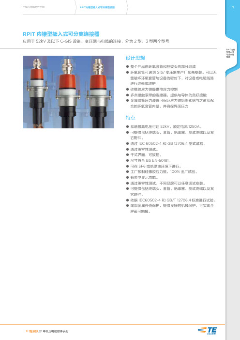
特点
● 系统最高电压可达 52kV,额定电流 1250A。 ● 可提供包括终端头、套管、绝缘塞、测试终端以及其
它附件。 ● 通过 IEC 60502-4 和 GB 12706.4 型式试验。 ● 通过兼容性测试。 ● 干式界面,可拔插。 ● 尺寸符合 BS EN-50181。 ● 可在 SF6 或绝缘油环境下进行。 ● 工厂预制硅橡胶应力锥,100% 出厂试验。 ● 有带电显示功能。 ● 通过兼容性测试,不同品牌可以任意调试安装。 ● 可提供包括终端头、套管、绝缘塞、测试终端以及其
TE能源部 /// 中低压电缆附件手册
中低压电缆附件手册
绝缘母座
绝缘塞 绝缘套管
RPIT内锥型插入式可分离连接器
7733
验电端子的静电电容
规格 静电电容
2 # (800A) RPIS-2-IS
Max. 9 pF
加强基类型转台插座安装说明书

200 AMP 15 KV class and 25 KV class loadbreak rotatable feedthru insert installation instructionsClean &lubricateBushing wellBail tabsHold down bailassemblyRotatable feedthru insertDISCLAIMER OF WARRANTIES AND LIMITATION OF LIABILITYThe information, recommendations, descriptions and safety notations in this document are based on Eaton Corporation’s (“Eaton”) experience and judgment and may not cover all contingencies. If further information is required, an Eaton sales office should be consulted. Sale of the product shown in this literature is subject to the terms and conditions outlined in appropriate Eaton selling policies or other contractual agreement between Eaton and the purchaser.THERE ARE NO UNDERSTANDINGS, AGREEMENTS, WARRANTIES, EXPRESSED OR IMPLIED, INCLUDING WARRANTIES OF FITNESS FOR A PARTICULAR PURPOSE OR MERCHANTABILITY, OTHER THAN THOSE SPECIFICALL Y SET OUT IN ANY EXISTING CONTRACT BETWEEN THE PARTIES. ANY SUCH CONTRACT STATES THE ENTIRE OBLIGATION OF EATON. THE CONTENTS OF THIS DOCUMENT SHALL NOT BECOME PART OF OR MODIFY ANY CONTRACT BETWEEN THE PARTIES. In no event will Eaton be responsible to the purchaser or user in contract, in tort (including negligence), strict liability or other-wise for any special, indirect, incidental or consequential damage or loss whatsoever, including but not limited to damage or loss of use of equipment, plant or power system, cost of capital, loss of power, additional expenses in the use of existing power facilities, or claims against the purchaser or user by its customers resulting from the use of the information, recommendations and descriptions contained herein. The information contained in this manual is subject to changewithout notice.iINSTALLATION INSTRUCTIONS MN650034EN November 2016ContentsDISCLAIMER OF WARRANTIES AND LIMITATION OF LIABILITY . . . . . . . . . . . . . . . . . . . . . . . . . . . . . . . . . . . .I SAFETY FOR LIFE . . . . . . . . . . . . . . . . . . . . . . . . . . . . . . . . . . . . . . . . . . . . . . . . . . . . . . . . . . . . . . . . . . . . . . . . .III SAFETY INFORMATION . . . . . . . . . . . . . . . . . . . . . . . . . . . . . . . . . . . . . . . . . . . . . . . . . . . . . . . . . . . . . . . . . . . .III Safety instructions (iii)PRODUCT INFORMATION . . . . . . . . . . . . . . . . . . . . . . . . . . . . . . . . . . . . . . . . . . . . . . . . . . . . . . . . . . . . . . . . . . .1 Introduction (1)Additional information (1)Acceptance and initial inspection (1)Handling and storage (1)Standards (1)INSTALLATION INSTRUCTIONS . . . . . . . . . . . . . . . . . . . . . . . . . . . . . . . . . . . . . . . . . . . . . . . . . . . . . . . . . . . . . .1 Step 1 (1)Step 2 (2)Step 3 (2)Step 4 (2)REMOVAL INSTRUCTIONS . . . . . . . . . . . . . . . . . . . . . . . . . . . . . . . . . . . . . . . . . . . . . . . . . . . . . . . . . . . . . . . . . .2 ii INSTALLATION INSTRUCTIONS MN650034EN November 2016iiiINSTALLATION INSTRUCTIONS MN650034EN November 2016Eaton’s Cooper Power series products meet or exceed all applicable industry standards relating to product safety. We actively promote safe practices in the use and maintenance of our products through our service literature, instructional training programs, and the continuous efforts of all Eaton employees involved in product design, manufacture, marketing and service.We strongly urge that you always follow all locally approved safety procedures and safety instructions when working around high-voltage lines and equipment and support our “Safety For Life” mission.200 AMP 15 KV class and 25 KV class loadbreak rotatable feedthru insert installation instructionsProduct informationIntroductionEaton’s Cooper Power series Rotatable Feedthru Insertis used to provide dual bushings from a single apparatusbushing well. It makes converting radial-feed transformers tofeed-thru transformers and adding in-line arrester protectionboth easy and practical. Its patented, built-in torque-limiting ratchet prevents operators from accidentally breaking bushing well studs during installation. The ratchet feature also allows the operator to rotate the feedthru insert 360° to orient it in the best position for the application. The bail assembly supplied with the kit can be used to prevent the insert from moving.Eaton’s Cooper Power series 200 A Loadbreak Rotatable Feedthru Insert is designed to be operatedin accordance with normal safe operating procedures . These instructions are not intended to supersede or replace existing safety and operating procedures . The bushing insert should be installed and serviced only by personnel knowledgeable of good safety practices and fully trained on the installation and application of high voltage electrical equipment .All associated apparatus must be de-energized during installation, maintenance or removal .Read and understand the contents of this manualand follow all locally approved procedures and safety practices before installing or operating this equipment .Additional informationThese instructions cannot cover all details or variationsin the equipment, procedures, or process described nor provide directions for meeting every possible contingency during installation, operation, or maintenance. For additional information, contact your Eaton Representative.Acceptance and initial inspectionEach Rotatable Feedthru Insert is in good condition when accepted by the carrier for shipment. Upon receipt, inspect the shipping container for signs of damage. Unpack the Rotatable Feedthru Insert and inspect it thoroughly for damage incurred during shipment. If damage is discovered, file a claim with the carrier immediately.Clean &lubricate BushingwellBail tabsHold downbailassemblyRotatablefeedthruinsertFigure 1 . Rotatable feedthru insert installation into bushing wellHandling and storageBe careful during handling and storage of the Rotatable Feedthru Insert to minimize the possibility of damage. If the Rotatable Feedthru Insert is to be stored for any length of time prior to installation, provide a clean, dry storage area.StandardsISO 9001:2000 Certified Quality Management System Installation instructionsStep 1Clean and lubricate●●Visually inspect for damage and correct rating.●●Verify that apparatus is de-energized.●●Clean any foreign contaminants from the surfaces of the bushing well and rotatable feedthru insert interfaces.●●Apply a thin even coating of grease to mating surfaces of the rotatable feedthru insert and the bushing well. (Refer to Figure 1.)1INSTALLATION INSTRUCTIONS MN650034EN November 2016200 AMP 15 KV class and 25 KV class loadbreak rotatable feedthru insert installation instructionsStep 2Install●●Place base of rotatable feedthru insert into bushing well.●●Turn rotatable feedthru insert clockwise onto bushing well stud.●●An audible click signals that threads and interface are fully seated.●●Continue clockwise rotation to position feedthru.●●Insert the holddown bail hooks into bail tabs and assemble bail across the center of the feedthru insert using wing nuts.Step 3Ground●●Attach copper drain wire (Minimum #14 AWG) to bushing insert drain wire tab.●●Connect drain wire to system ground.Step 4Remove caps●●Remove red shipping caps prior to energizing.Do not energize unit while red shipping caps are on rotatable feedthru insert . Loadbreak Elbows, Surge Arresters, or insulated protective caps should be installed before rotatable feedthru insert is energized .●●Install mating products following instructions supplied with the product.Removal instructions●●De-energize apparatus and verify apparatus isde-energized.●●Remove mating products and place in stand-off device ora clean, dry location.●●Loosen wing nuts of holddown bail and remove bail assembly.●●Remove drain wire.●●Grab bushing interfaces of rotatable feedthru insert and turn counterclockwise until feedthru comes loose from bushing well.2INSTALLATION INSTRUCTIONS MN650034EN November 2016200 AMP 15 KV class and 25 KV class loadbreak rotatable feedthru insert installation instructionsThis page is intentionally left blank.3INSTALLATION INSTRUCTIONS MN650034EN November 2016Eaton1000 Eaton Boulevard Cleveland, OH 44122United StatesEaton’s Power Systems Division 2300 Badger Drive Waukesha, WI 53188United States/cooperpowerseries© 2016 EatonAll Rights ReservedPrinted in USAPublication No. MN650034EN Rev 0 (Supersedes S500131 Rev. 0) November 2016 Eaton is a registered trademark.All trademarks are propertyof their respective owners.For Eaton's Cooper Power series productinformationcall 1-877-277-4636 or visit:/cooperpowerseries.。
- 1、下载文档前请自行甄别文档内容的完整性,平台不提供额外的编辑、内容补充、找答案等附加服务。
- 2、"仅部分预览"的文档,不可在线预览部分如存在完整性等问题,可反馈申请退款(可完整预览的文档不适用该条件!)。
- 3、如文档侵犯您的权益,请联系客服反馈,我们会尽快为您处理(人工客服工作时间:9:00-18:30)。
1/2" - 12,7 mm 扭矩扳手
IS T-400TB/G-CN-02 Page 7 of 8
5. 将绝缘塞外表面和对应的插拔头接口内表面擦拭干净,然后把硅脂均匀的涂抹在上面. 6. 将绝缘塞插在插拔头的接口内. 7. 用扭矩扳手(24mm的螺栓套筒) 将其拧紧到50Nm.(要点见最后一页)
橡皮帽
图5 PVC内护套
5
胶带 (2 层)
防水锡
IS Breakout kit Page 3 of 4
图6
防水锡 临时固定胶带
第2条铜编织带
7. 包绕2层胶带(50%重叠),由PVC内 护套开始,直至外护套5mm的为止(防 水锡的上面)。
8. 将第2条铜编织带的防水锡与包绕好的胶带对齐 (如图6),用胶带在下面将其临时固定。
滑移到标记带为止.
.
3. 将PVC胶带移除.
压接端子的安装
电缆配套管末端
压接之前,确认Z: 150mm 到160mm之间 压接之后,确认Z: 155mm 到165mm之间
Z
压接顺序
压接端子 接触面 设备套管
1. 对于铝制线芯,在压接前应该用钢刷刷一下线芯,将表面氧化层去除. 2. 将端子套在线芯上,调整端子的位置,使端子的螺钉通孔对准设备套管的螺钉通孔. 3. 在压接之前,确认:”Z”一定要在150mm到160mm之间,然后进行压接. 4. 在压接之后,确认:”Z”一定要在155mm到165mm之间. 5. 除去由于压接而产生的毛刺,然后将其擦拭干净.
22mm
固定螺丝
L ≥ 130 mm 延长管
22 mm 螺栓套筒
1/2" - 12,7 mm 扭矩扳手
3. 将固定螺丝插到设备套管的螺钉通孔内. 4. 用扭矩扳手(22mm的螺栓套筒,130mm的延长管)将其拧紧到50Nm.(要点见最后一页)
* 只能用所提供的硅脂
润滑硅脂
24mm
绝缘塞
24 mm 螺栓通孔
EUROMOLD N.பைடு நூலகம்.
Zuid III - Industrielaan 12 B-9320 EREMBODEGEM-AALST – BELGIUM Tel: +32 (0)53/85 02 11 – Telefax: +32 (0)53/83 10 13
8. 如图 将剥除电缆的绝缘层. 9. 将临时固定的端子从电缆上移除.
5. 在距离外护套末端70mm处用PVC带做一个标 记带.
保护延长管
半导电层 绝缘层
斜角
IS T-400TB/G-CN-02 Page 3 of 8
25 230
1. 确认:保护延长管的末端到导体线芯末端的距离为230. 2. 保留25mm长的半导电层,其余剥除. 3. 去除绝缘末端的锋利尖角,将绝缘末端切成平滑的斜角,
4. 在短铜编织带的防水锡处起,向下包绕2层
设备相匹配。
(50%重叠),长度为120mm的胶带。(图2)
2. 保留30mm铠装层,其余剥除。将铠装用 镀锡铜线扎起。
3. 保留40mmPVC内护套,其余剥除。
5. 将编织带的防水锡定位在距离外护套末端 5mm处。(图3)
6. 先将一层恒力弹簧绕过铜编织带,包绕在铠 装上。然后把恒力弹簧以上部分的编织带向下 折,将整个恒力弹簧余下的部分包绕在铠装和 铜编织带上。( 图 4 )
3 x 电缆配套管 - 411CA-W 3 x 固定螺丝 - 400TCS 3 x 压接端子 - TBC-X 3 x 绝缘塞+橡皮帽- 400BIPA
- 应控胶泥 - MFC - 防水胶泥 - MWS - 润滑硅脂 + 绝缘清洁巾 - 安装说明书
本产品应由经过严格培训并有高压电力设备安装经验的人员来安装 本安装手册不能够 代替足够的安装培训和工作经验,不能够提供种种可能发生的意外事故 不按照安装手册中的步骤进行安装可产生严重后果 重要须知:在安装之前,电缆和有关设备必须切断电源,锁定和加上标识
注 : 两个铜编织带不要互相接触
图 7a
防水胶泥A
图 7b
图 7c
20
20
防水胶泥B
防水胶泥B
防水胶泥A
第2条铜编织带
胶带 防水胶泥B
防水胶泥A
铜编织带
铜编织带
9. 从防水胶泥A上切下2小块防水胶泥(大约20mm),将它们分别放在两个铜编织带的防水锡下面。 其余的胶泥待用。(7a)
10. 将第二条铜编织带(如图7b)包绕在三芯铜屏蔽上,剪下去多余的部分,然后用恒力弹簧将其 固定。
11. 将防水胶泥B包绕在电缆外护套及铜编织带上,胶泥可适度拉长并完全包绕在电缆外护套上。 将临时固定的胶带去除。(7c)
IS Breakout Kit Page 4 of 4
图8 分支手套
分支手套及保护延长管的安装 (也可选择冷缩分支手套及冷缩保护延长管)
图9
图 10
收缩顺序
保护延长管 收缩顺序
保护延长管
半导电层
应力控制胶泥
10
4. 将电缆擦拭干净,不要将任何导电颗粒残留在电缆的绝缘层上.(由线芯绝缘擦向半导电层) 5. 如图所示,将应力控制胶泥包绕在半导电层和线芯绝缘层的过渡带上(一半帖在半导电层,一半帖在线芯绝缘上).
保护延长管
防水胶泥的安装
防水胶泥
标记带
擦拭干净
1. 可用砂纸将标记带与延长管末端的部分稍做打磨,然后擦拭干净.
a Nexans company
注意:在安装之前请通读安装手册
安装手册
IS T-400TB/G-CN-02
Page 1 of 8 - Nov. 2006
T-(K)(M)(P)400TB/G
T 型可分离插拔头 - C型接口
用于3芯电缆 最高工频电压为42kV
配件:
3 x T型插拔头外壳 - 400BT/G
- 将分支手套滑入线芯 直至外护套。
- 把线芯张开,尽可能的将 分支手套套在电缆的根部。 热缩分支手套的收缩方向 如图所示。
- 把保护延长管分别套在三 根线芯上。确认:延长管 与分支手套相重叠。热缩 保护延长管的收缩方向如 图所示。
IS T-400TB/G-CN-02 Page 2 of 8
设备
设备套管 半导电层
电缆夹
系统接地
系统接地
要点:
* 在使用扭矩扳手之前要检查在其螺纹上是否有硅脂,如果有要擦拭干净。 * 在通电情况下不允许将插拔头和设备套管分离,也不许在通电情况下安装插拔头。 * 不要将含有炭氢化合物的油或者溶解剂弄在插拔头上,以免损伤EPDM表面。如果有应
该赶紧擦掉,保持表面干燥。
a Nexans company
2. 如图所示将防水胶泥包绕在打磨过的外护套上面.
防水胶泥
PVC胶带
5 3. 可以用PVC胶带将防水胶泥固定.
IS T-400TB/G-CN-02 Page 4 of 8
电缆配套管的安装
保护延长管
标记带
电缆配套管
PVC胶带
1. 为防止导体尖端划破配套管内表面,用PVC胶带将导体线芯包绕.
2. 将润滑硅脂*均匀的涂抹在绝缘层的外表面及防水胶泥上和电缆配套管的内表面.将电缆配套管套在电缆上并一直
9006-CN
IS Breakout kit Page 2 of 4
电缆的准备
图1 胶带
图3 图2
60
5
450最小
铜屏蔽
120
胶带 (2层)
40 30
PVC内护套
800
镀锡铜线
铠装
短铜编织带 图4
外护套
短铜编织带 恒力弹簧 铠装 防水锡
恒力弹簧
1.从电缆末端剥除最小450mm长的电缆外护套,
具体长度也应该与其连接的电器
* 只能用所提供的硅脂
设备
将T型插拔头外壳安装到电缆上
IS T-400TB/G-CN-02 Page 5 of 8
擦拭干净 润滑硅脂
T型插拔头主体
1. 将电缆配套管的外表面擦拭干净,然后把润滑硅脂均匀的涂抹在配套管的外表面和插拔头的内表面.
设备套管中线
2. 调整插拔头,使之与端子的接触面相垂直(如图).将T型插拔头主体套在电缆上,慢慢的向前滑动,一直滑动到不能 再向前推进为止. .
设备
M
280
半导电层
M 截断
C
C
15
保护延长管
70
标记带
1. 三芯电缆的分支手套按照对应的安装手册安装, 6. 如图所示,在电缆上做上标记,标出电缆上对应的端子末端位置. 然后:
2. 将压接端子临时先固定在设备套管上
7. 量出端子的深度,然后如图 截断电缆.
3. 将电缆靠近设备套管,放到适当的位置
4. 剥除电缆末端的保护延长管和铜屏蔽,使电缆 末端到外护套末端的距离为280mm. 注意:不要损伤到绝缘层.
3. 确认:电缆配套管在安装插拔头的过程中没有移位.
* 只能用所提供的硅脂
IS T-400TB/G-CN-02 Page 6 of 8
与设备相连接
润滑硅脂 设备套管
1. 将设备套管的外表面和对应插拔头主体接口的内表面擦拭干净,均匀的涂上硅脂. 2. 将插拔头主体的阴性接口套在设备套管上.(要点见最后一页)
8. 擦拭干净橡皮帽的内表面(不要涂抹硅脂),将其用力扣在插拔头上,直到”咔吧”一声为止. * 只能用所提供的硅脂
IS T-400TB/G-CN-02 Page 8 of 8
接地和电缆的固定
接地线
系统接地 接地铜编织带
将接地铜编织带和接地线接地,用电缆夹将其固定.
注:插拔头和设备套管不应该承受电缆 的全部重量,所以必须用电缆夹将其 夹紧.