IGZO 高迁移率氧化物薄膜晶体管
晶态IGZO_薄膜晶体管的研究进展

第 38 卷第 8 期2023 年 8 月Vol.38 No.8Aug. 2023液晶与显示Chinese Journal of Liquid Crystals and Displays晶态IGZO薄膜晶体管的研究进展姜柏齐1,刘斌1,刘贤文1,张硕1,翁乐1,史大为2,郭建2,苏顺康2,姚琪3,宁策3,袁广才3,王峰1,喻志农1*(1.北京理工大学光电学院,北京市混合现实与先进显示技术工程研究中心,北京 100081;2.重庆京东方显示技术有限公司,重庆 400714;3.北京京东方显示技术有限公司,北京 101520)摘要:随着显示技术的不断发展,对高性能、高稳定性的薄膜晶体管(Thin Film Transistor,TFT)的需求日趋增加,通过结晶改善薄膜晶体管性能的方法受到大量关注。
当前,铟镓锌氧化物(IGZO)材料由于具有迁移率高、柔性好、透明度高等优势,被广泛用于薄膜晶体管的沟道中,而改善IGZO沟道层的结晶形态也成为研究热点。
本文总结了晶态IGZO薄膜晶体管器件的研究进展,详细介绍了IGZO系化合物的晶体结构,重点阐述了单晶、c轴取向结晶、六方多晶型、尖晶石型、纳米晶型和原生结晶型IGZO的结构和各晶态IGZO薄膜晶体管的制备方法、器件性能和稳定性,深入分析其微观结构,总结物理特性,阐述不同晶系结构的结晶机理,建立不同晶体结构与电学特性的关系,最后对晶态IGZO薄膜晶体管的发展进行展望。
关键词:晶态IGZO薄膜;薄膜晶体管;晶体结构;研究进展中图分类号:TN321+.5 文献标识码:A doi:10.37188/CJLCD.2023-0121Research progress on crystalline IGZO thin film transistor JIANG Bai-qi1,LIU Bin1,LIU Xian-wen1,ZHANG Shuo1,WENG Le1,SHI Da-wei2,GUO Jian2,SU Shun-kang2,YAO Qi3,NING Ce3,YUAN Guang-cai3,WANG Feng1,YU Zhi-nong1*(1.School of Optics and Photonics, Beijing Engineering Research Center of Mixed Reality and Advanced Display, Beijing Institute of Technology, Beijing 100081, China;2.Chongqing BOE Display Technology Co., Ltd., Chongqing 400714, China;3.Beijing BOE Display Technology Co., Ltd., Beijing 101520, China)Abstract: With the development of display technology, the demand for high-performance and high-stability thin film transistors (TFTs) is increasing. The method of improving the performance of thin film transistors through crystallization has received a lot of attention. Currently, indium gallium zinc oxide (IGZO) materials are widely used in the channels of thin film transistors due to their advantages such as high mobility, flexibility,and high transparency. Improving the crystalline morphology of the IGZO channel layer has become a research hotspot.This article summarizes the research progress of crystalline IGZO thin film transistor devices,文章编号:1007-2780(2023)08-1031-16收稿日期:2023-04-04;修订日期:2023-05-10.基金项目:国家重点研发计划(No.2021YFB3600703)Supported by National Key Research and Development Program of China(No.2021YFB3600703)*通信联系人,E-mail: znyu@第 38 卷液晶与显示introduces in detail the crystal structure of IGZO compounds, and focuses on the structure of single crystalline,c-axis-aligned crystalline,hexagonal polycrystalline,spinel,nanocrystalline,and protocrystalline IGZO,as well as the preparation methods,device performance,and stability of various crystalline IGZO thin-film transistors.We also analyze the microstructure of crystalline IGZO,summarize the physical properties,describe the crystallization mechanism and establish the relationship between crystal structure and electrical properties. At last, the development of crystalline IGZO thin film transistor is prospected.Key words: crystalline IGZO film; thin film transistor; crystal structure; research progress1 引言薄膜晶体管(TFT)是使用半导体材料制成的绝缘栅极场效应管。
IGZO薄膜晶体管概述

IGZO薄膜晶体管概述作者:徐海燕来源:《科学与信息化》2017年第16期摘要随着科技的进步和社会的发展,传统的晶体管技术因为自身较多的限制引发出越来越多的使用局限。
金属氧化物IGZO薄膜晶体管应运而生并迅速成为了众科学家研究的热点。
金属氧化物IGZO拥有很多优秀的特性例如:迁移率较高、稳定性好、制造工艺简单等。
本文通过对金属氧化物IGZO的结构特点以及其自身的介绍,总结出影响金属氧化物IGZO薄膜晶体管性能的主要因素。
从而使读者能够对IGZO薄膜晶体管有一个较为全面的认识。
关键词薄膜晶体管;氧化IGZO;氧化物1 前言随着社会生活的极大丰富,人民物质生活水平越来越高,电脑走进了千家万户并逐渐成为家庭最主要的娱乐休闲平台之一。
人们在电脑的液晶显示器的选择上也逐渐趋向于选择购买屏幕够大清晰度较高的产品。
随着屏幕尺寸的增大,其内部所使用的驱动电路频率也同样水涨船高。
现在传统的液晶显示器所使用的非晶硅薄膜晶体管的迁移率很难满足当前的市场需求,非晶硅薄膜晶体管的迁移率一般保持在0.5左右。
一台液晶显示器的屏幕尺寸如果超过了80in,其驱动电路的频率就需要至少达到120Hz,并且使用的晶体管迁移率需要达到1cm2/V·s以上,而现在所使用的非晶硅薄膜晶体管由于本身降低的迁移率和较为难以处理的物理性质越来越难以满足现代市场上的技术需求。
目前国内使用的主要晶体管种类有非晶硅、多晶硅、非晶IGZO。
多晶硅具有良好的迁移率和物理性能,但是多晶硅薄膜晶体管的均一性很差,制作工艺温度极低,这就使得其制作成本和难度极高;然而金属氧化物IGZO TFT迁移率较高,虽然不及多晶硅薄膜晶体管,但是其拥有者较好的均一性、透明度和较低的制作温度和工艺难度,能够较好地满足大尺寸液晶屏幕和有源有机电致发光的需求,备受人们的关注,并成为显示器研究领域的研究重点。
2 非晶金属氧化物IGZO非晶金属氧化物IGZO由In2O3、Ga2O3和ZnO构成,禁带宽度在3.5eV左右,是一种N 型半导体材料。
IGZO薄膜晶体管概述

IGZO薄膜晶体管概述摘要随着科技的进步和社会的发展,传统的晶体管技术因为自身较多的限制引发出越来越多的使用局限。
金属氧化物IGZO薄膜晶体管应运而生并迅速成为了众科学家研究的热点。
金属氧化物IGZO拥有很多优秀的特性例如:迁移率较高、稳定性好、制造工艺简单等。
本文通过对金属氧化物IGZO的结构特点以及其自身的介绍,总结出影响金属氧化物IGZO薄膜晶体管性能的主要因素。
从而使读者能够对IGZO薄膜晶体管有一个较为全面的认识。
关键词薄膜晶体管;氧化IGZO;氧化物1 前言随着社会生活的极大丰富,人民物质生活水平越来越高,电脑走进了千家万户并逐渐成为家庭最主要的娱乐休闲平台之一。
人们在电脑的液晶显示器的选择上也逐渐趋向于选择购买屏幕够大清晰度较高的产品。
随着屏幕尺寸的增大,其内部所使用的驱动电路频率也同样水涨船高。
现在传统的液晶显示器所使用的非晶硅薄膜晶体管的迁移率很难满足当前的市场需求,非晶硅薄膜晶体管的迁移率一般保持在0.5左右。
一台液晶显示器的屏幕尺寸如果超过了80in,其驅动电路的频率就需要至少达到120Hz,并且使用的晶体管迁移率需要达到1cm2/V·s以上,而现在所使用的非晶硅薄膜晶体管由于本身降低的迁移率和较为难以处理的物理性质越来越难以满足现代市场上的技术需求。
目前国内使用的主要晶体管种类有非晶硅、多晶硅、非晶IGZO。
多晶硅具有良好的迁移率和物理性能,但是多晶硅薄膜晶体管的均一性很差,制作工艺温度极低,这就使得其制作成本和难度极高;然而金属氧化物IGZO TFT迁移率较高,虽然不及多晶硅薄膜晶体管,但是其拥有者较好的均一性、透明度和较低的制作温度和工艺难度,能够较好地满足大尺寸液晶屏幕和有源有机电致发光的需求,备受人们的关注,并成为显示器研究领域的研究重点。
2 非晶金属氧化物IGZO非晶金属氧化物IGZO由In2O3、Ga2O3和ZnO构成,禁带宽度在3.5eV左右,是一种N型半导体材料。
氧化锌基导体 igzo

氧化锌基导体 igzo
氧化锌基导体IGZO(Indium Gallium Zinc Oxide)是一种新
型的半导体材料,由铟(Indium)、镓(Gallium)和锌(Zinc)的
氧化物组成。
IGZO因其优良的电学性能而备受关注,具有高电子迁
移率、透明度高、较低的工作电压和低功耗等特点,在薄膜晶体管(TFT)等电子器件中有着广泛的应用前景。
首先,从化学成分角度来看,IGZO是由铟、镓和锌的氧化物组
成的,这意味着它具有优异的半导体特性。
铟和镓的加入可以有效
提高材料的电子迁移率,而锌的加入则有助于提高材料的稳定性和
可制备性。
其次,从电学性能角度来看,IGZO具有高电子迁移率,这意味
着在电子器件中可以实现更快的电子传输速度,有助于提高器件的
性能和响应速度。
同时,IGZO材料的透明度也很高,适用于制备透
明电子器件,比如柔性显示屏等。
此外,IGZO材料在制备薄膜晶体管(TFT)方面具有独特优势。
相比传统的非晶硅材料,IGZO材料可以实现较低的工作电压和更低
的功耗,有助于减小电子器件的能耗并延长电池寿命。
总的来说,氧化锌基导体IGZO具有优良的电学性能和广泛的应用前景,对于未来电子器件的发展具有重要意义。
希望这些信息能够满足你的需求,如果你还有其他问题,欢迎继续提问。
氧化物薄膜晶体管

氧化物薄膜晶体管
1 关于氧化物薄膜晶体管
氧化物薄膜晶体管(Oxide Thin Film Transistor,简称OTFT)是一种利用氧化物材料作为晶体管通道的器件,并且这种氧化物材料的厚度在一百到几千纳米之间,因此其被称之为薄膜晶体管。
由于氧化物材料具有结构简单,制作工艺简单,电性优良,而且能够直接制备在易受损的衬底表面,因而OTFT被众多研究者视为如今新型平板显示器(Panel Display)的重要关键。
2 优势
OTFT特别适合立体显示和柔性显示技术,如头戴式虚拟现实(Headmounted Virtual Reality)显示器,因其可实现大尺寸或超大尺寸集群控制,而且具有器件构筑厚度超薄,弯曲抗性强,散热快,耐腐蚀性强,适应度宽等优势,而这一优势显著减少了电子消费品的厚度与体积,大大增强了设备的可靠性和安全性,并且可满足响应速度与大视角要求。
3 应用
OTFT众多优势使其在消费类电子产品领域获得了快速发展,其应用领域不仅包括有表面张力显示屏,头显,可穿戴设备;还可适用于手机,数码摄像机,数字相框,MP3,GPS等多种产品。
而手机,电视和信息显示设备的发展已推动OTFT成为新一代显示技术的关键。
可预言,OTFT技术将成为未来将来消费性电子产品的重要元件。
4 结论
由于其具有结构简单,电性优良,灵敏极高,构筑厚度超薄,弯曲抗力强等优势,OTFT技术推动了消费类电子产品的发展,并预示着今后消费类电子产品依赖OTFT技术将更加广泛。
退火工艺对基于InGaZnO薄膜晶体管性能的影响

退火工艺对基于InGaZnO薄膜晶体管性能的影响聂国政;黄笃之;钟春良;许英【摘要】铟嫁锌氧化物(IGZO)以其迁移率高、均匀性好、对可见光透明、制备温度低和成本低等优点被认为是金属氧化物薄膜晶体管(Thin-Film Transistor (TFT))理想的有源材料,采用磁控溅射法制备了基于SiO2绝缘层的IGZO-TFT 器件。
研究铟嫁锌氧化物有源层薄膜的前退火工艺(pre- annealing)和后退火工艺(post- annealing)对IGZO-TFT器件的电学性能的影响,其电学测试数据表明,相对于后退火工艺(post- annealing),前退火工艺处理的IGZO-TFT 器件的展示了更高的场效应迁移率(3.5 cm2V-1s-1)和更好的开关比(107)。
同时,十八烷基三氯硅烷(OTS)对改善SiO2绝缘层与铟嫁锌氧化物半导体有源层之间的界面接触效果显著。
【期刊名称】《湖南科技学院学报》【年(卷),期】2015(000)010【总页数】3页(P19-21)【关键词】金属氧化物;薄膜晶体管;退火;表面修饰【作者】聂国政;黄笃之;钟春良;许英【作者单位】湖南科技大学物理与电子科学学院,湖南湘潭 411201;湖南科技大学物理与电子科学学院,湖南湘潭 411201;湖南工业大学理学院,湖南株洲412007;湖南科技大学物理与电子科学学院,湖南湘潭 411201【正文语种】中文【中图分类】TN321.5高性能的TFT(薄膜晶体管)是液晶显示、有源驱动有机发光二极管显示(AMOLED)等产业的基础和核心器件。
原有的硅基材料TFT由于其低的迁移率、生产工艺复杂、成本居高不下、均匀性差,良品率低等难以克服的问题,限制了其在大尺寸显示领域的进一步发展,因此迫切需要研究新的具有替代硅材料潜力的有源材料。
基于金属氧化物(Metal-oxide, 简称MO,如ZnO、InZnO、InGaZnO等)半导体的薄膜晶体管以其迁移率高、均匀性好、对可见光透明、制备温度低和成本低等优点被认为是适合驱动有机发光二极管(OLED)和高分辨率液晶显示(LCD)的理想有源器件[1, 2]。
背沟道刻蚀型氧化物薄膜晶体管的研究

背沟道刻蚀型氧化物薄膜晶体管的研究全文共四篇示例,供读者参考第一篇示例:背沟道刻蚀型氧化物薄膜晶体管(Back-gate etching type Oxide thin film transistors, 简称BEOTFT)是一种新型的薄膜晶体管结构,具有优异的性能和潜在的应用前景。
该技术是在晶体管背面进行刻蚀,形成掺杂和氧化层,从而实现了晶体管的优化设计和制备。
本文将对BEOTFT的研究进行探讨,分析其制备方法、性能特点以及在应用领域的潜力。
一、背槽道刻蚀型氧化物薄膜晶体管的制备方法1、基板制备:首先需要选择合适的基板材料,一般采用玻璃或硅基板。
然后对基板进行清洗和处理,以保证其表面的光洁度和成膜性。
2、氧化物薄膜薄膜沉积:在清洁的基板上,利用化学气相沉积(CVD)或者溅射等方法沉积氧化物薄膜。
氧化物薄膜主要用于作为晶体管的绝缘层。
3、掺杂层形成:在氧化物薄膜上通过背面刻蚀形成掺杂层,提高晶体管的性能。
4、源漏极电极和栅极的沉积:利用光刻和蒸发等工艺,在氧化物薄膜上沉积源漏极电极和栅极等金属电极。
5、退火处理:最后对晶体管进行热处理,以提高薄膜的结晶性和稳定性。
1、低功耗:由于氧化物薄膜的优异绝缘性能和掺杂层的高效能,使晶体管具有低功耗的特点。
2、高移动度:背槽道刻蚀型氧化物薄膜晶体管通常具有高电子迁移率和载流子迁移率,使得其在高频率和高速应用上具有优势。
4、制备成本低:相对于传统的薄膜晶体管,背槽道刻蚀型氧化物薄膜晶体管的制备成本更低,具有较高的经济性。
基于以上性能特点,背槽道刻蚀型氧化物薄膜晶体管在显示技术、传感器、光电器件等领域有着广泛的应用前景。
背槽道刻蚀型氧化物薄膜晶体管作为新型晶体管结构,具有广阔的应用前景。
在显示技术领域,其高速度、高分辨率和低功耗的特点使其成为下一代面板技术的主要选择。
在传感器领域,其高灵敏度和稳定性使其在生物医学、环境检测等领域有着重要的应用价值。
在光电器件领域,其高电子迁移率和稳定性使其成为制备高性能器件的重要手段。
金属氧化物薄膜晶体管电特性参数的提取
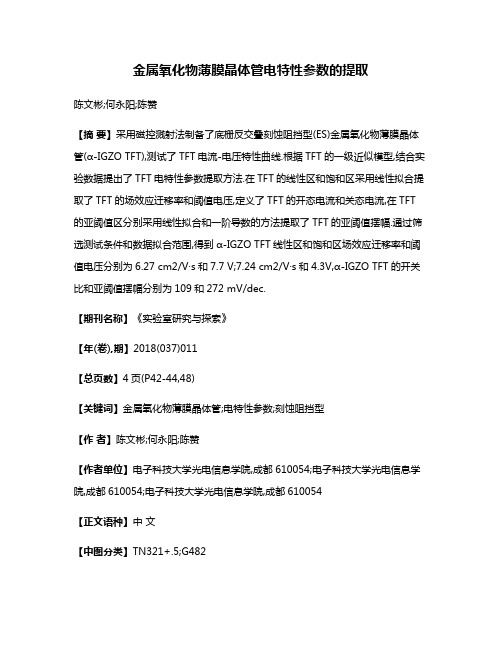
金属氧化物薄膜晶体管电特性参数的提取陈文彬;何永阳;陈赞【摘要】采用磁控溅射法制备了底栅反交叠刻蚀阻挡型(ES)金属氧化物薄膜晶体管(α-IGZO TFT),测试了TFT电流-电压特性曲线.根据TFT的一级近似模型,结合实验数据提出了TFT电特性参数提取方法.在TFT的线性区和饱和区采用线性拟合提取了TFT的场效应迁移率和阈值电压,定义了TFT的开态电流和关态电流,在TFT 的亚阈值区分别采用线性拟合和一阶导数的方法提取了TFT的亚阈值摆幅.通过筛选测试条件和数据拟合范围,得到α-IGZO TFT线性区和饱和区场效应迁移率和阈值电压分别为6.27 cm2/V·s和7.7 V;7.24 cm2/V·s和4.3V,α-IGZO TFT的开关比和亚阈值摆幅分别为109和272 mV/dec.【期刊名称】《实验室研究与探索》【年(卷),期】2018(037)011【总页数】4页(P42-44,48)【关键词】金属氧化物薄膜晶体管;电特性参数;刻蚀阻挡型【作者】陈文彬;何永阳;陈赞【作者单位】电子科技大学光电信息学院,成都610054;电子科技大学光电信息学院,成都610054;电子科技大学光电信息学院,成都610054【正文语种】中文【中图分类】TN321+.5;G4820 引言薄膜晶体管技术是平板显示的核心技术[1],其所采用的半导体材料经历了氢化非晶硅(α-Si:H)、纳米晶硅和低温多晶硅(LTPS)的发展[2-3]。
近年来更是出现了以α-IGZO为代表的金属氧化物TFT[4-5],国内也已经将α-IGZO TFT引入到了实验教学中[6]。
TFT性能的高低以TFT的特性参数来表征,TFT的特性参数须从TFT电流-电压特性,即转移特性曲线和输出特性曲线中提取。
尽管Shur等建立了精确的α-Si:H TFT和LTPS TFT物理模型[7],但是,由于物理概念清晰,使用相对简单,TFT的电流-电压特性仍然常用TFT的一级模型来描述,实验室中或新型TFT技术开发中经常用来结合实验数据进行TFT特性参数提取。
- 1、下载文档前请自行甄别文档内容的完整性,平台不提供额外的编辑、内容补充、找答案等附加服务。
- 2、"仅部分预览"的文档,不可在线预览部分如存在完整性等问题,可反馈申请退款(可完整预览的文档不适用该条件!)。
- 3、如文档侵犯您的权益,请联系客服反馈,我们会尽快为您处理(人工客服工作时间:9:00-18:30)。
High mobility thin film transistors with indium oxide/gallium oxide bi-layer structures S.-L. Wang, J.-W. Yu, P.-C. Yeh, H.-W. Kuo, L.-H. Peng, A. A. Fedyanin, E. D. Mishina, and A. S. SigovCitation: Applied Physics Letters 100, 063506 (2012); doi: 10.1063/1.3683518View online: /10.1063/1.3683518View Table of Contents: /content/aip/journal/apl/100/6?ver=pdfcovPublished by the AIP PublishingArticles you may be interested inHigh mobility amorphous InGaZnO4 thin film transistors formed by CO2 laser spike annealingAppl. Phys. Lett. 106, 123506 (2015); 10.1063/1.4914373High stability mechanisms of quinary indium gallium zinc aluminum oxide multicomponent oxide films and thin film transistorsJ. Appl. Phys. 117, 045309 (2015); 10.1063/1.4906619Coplanar amorphous-indium-gallium-zinc-oxide thin film transistor with He plasma treated heavily doped layer Appl. Phys. Lett. 104, 022115 (2014); 10.1063/1.4862320Thin-film transistors with amorphous indium gallium oxide channel layersJ. Vac. Sci. Technol. B 24, 2702 (2006); 10.1116/1.2366569Transparent thin-film transistors with zinc indium oxide channel layerJ. Appl. Phys. 97, 064505 (2005); 10.1063/1.1862767High mobility thin film transistors with indium oxide/gallium oxide bi-layer structuresS.-L.Wang,1J.-W.Yu,1P.-C.Y eh,1H.-W.Kuo,1L.-H.Peng,1,a)A.A.Fedyanin,2E.D.Mishina,3and A.S.Sigov31Department of Electrical Engineering,Institute of Photonics and Optoelectronics,andCenter for Emerging Materials and Advanced Devices,National Taiwan University,Taipei106,Taiwan2Faculty of Physics,Lomonosov Moscow State University,Moscow119991,Russia3Moscow State Technical University of Radioengineering,Electronics,and Automation,Moscow119454,Russia(Received23November2011;accepted18January2012;published online9February2012)We investigate the transport properties of thin-film transistors using indium oxide(In2O3)/galliumoxide(Ga2O3)bi-layer stacks as the channel material.At low gate bias,we observe the transistorfield-effect mobility increases with thefilm resistivity to l FE¼51.3cm2/Vs and ON/OFF currentratio to108due to combinatorial layer thickness modulation.With the Ga2O3layer thickness ratioincrease to R¼14.35%,these observations are accompanied with one-order-of-magnitudereduction in the transistor subthreshold swing to0.38V/decade and suggest a trap-limitedconduction mechanism upon which the reduced scattering centers due to annihilation of subgapstates improve the device electric characteristics without post-growth annealing.V C2012AmericanInstitute of Physics.[doi:10.1063/1.3683518]Thinfilm transistors(TFTs)are an essential element for flat-panel displays and next-generation microelectronic devi-ces.1Hydrogenated amorphous silicon(a-Si:H)has been one of the widely used channel materials for TFTs.However,it suffers from issues such as low mobility(l<1cm2/Vs)and instability under illumination and electric bias stress.2 Alternative TFT channel design,comprising a superlattice structure made of hydrogenated silicon nitride(a-Si3N4:H)/ a-Si:H,has been proposed to increase the mobility by a fac-tor of5due to the quantization effect.2Recent study on amorphous indium-gallium-zinc-oxide(a-IGZO),3and their derivatives of a-IGO and a-IZO have drawn interest due to superior carrier mobility(l>10cm2/Vs)4and low tempera-ture processing.5Conventional wisdom suggests that the high carrier density in oxide semiconductors can be related to oxygen vacancies(V O)and other native defects.Model analysis indicates that carrier transport is controlled by mul-tiple trap-and-release events when the device is biased at low gate voltage with the Fermi level residing within the local-ized tail states.6The percolation conduction mechanism pre-vails when carriers are released to the non-localized states andfind the paths of least resistance.Wave function overlap between the s-orbitals of the adjacent In cations can make the carrier transportation insensitive to structure disorder, thus leading to highfield-effect mobility(l FE)in the oxide-based TFTs.7It was also noted that the formation energy of V O increases with Ga atoms,which can suppress the O-deficiency related defects and improve device stability.8,9 These observations outline a possibility to tailor the electric properties of oxide TFTs by adding Ga ions to enhance the material amorphization using the techniques such as sputter-ing10or solution-base process.11Here,we demonstrate another aspect of engineering the transport properties of oxide TFTs by mitigating the trap density of subgap states(D sg)in the In2O3/Ga2O3bi-layer system.We note that as the Ga2O3layer thickness ratio R, defined as tGa2O3/(tGa2O3þtIn2O3),increases from11%to 25%,the equivalentfilm resistivity(q eff)can span a wide range from104to107X cm with a rate of5.35%60.05%/ decade.From bottom-gate TFTs made of such In2O3/Ga2O3 bi-layer stack,we achieve a peakfield-effect mobility l FE¼51.3cm2/Vs,ON/OFF current ratio of108,and thresh-old voltage V T¼0.57V at a Ga2O3layer thickness ratio R¼14.35%(q eff¼9.2Â104X cm).These data are taken without post-growth annealing and concurred with an order of magnitude reduction in the TFT subthreshold swing to S¼0.38V/decade.Such behavior can be ascribed to a mech-anism of suppression of subgap trap density D sg in thin In2O3layers when interfaced to Ga2O3.8,9The preparation of In2O3/Ga2O3bi-layer stack materials used in this study was facilitated by the sputtering method at a temperature below60 C.The materials were typically grown at a sputtering power of70W and working pressure of4mTorr,withflow rate of argon(Ar)/oxygen(O2)fixed at 30/30sccm(standard cubic centimeter per minute).Under these conditions,a growth rate of0.14A˚/s and0.09A˚/s, respectively,can be found for depositing the In2O3and Ga2O3films on quartz substrates.A transmission line method (TLM),12with electrode patterns composed of200nm-thick molybdenum(Mo)stripes of4to16l m spacing,was applied to characterize q eff.Shown in the inset of Fig.1(a)are the resistance data taken on sample1designed to have7pairs of In2O3/Ga2O3 stack with3.5/0.57nm layer thickness in each pair.From a linear slopefitting of the resistance data to the Mo stripe spacing,one can extract q eff by considering a multiplication factor offilm thickness.This process allows us to examine the q eff distribution associated with various In2O3/Ga2O3a)Author to whom correspondence should be addressed.Electronic mail:peng@.tw.0003-6951/2012/100(6)/063506/4/$30.00V C2012American Institute of Physics100,063506-1APPLIED PHYSICS LETTERS100,063506(2012)layer thickness combination.Referred to Fig.1(a),logarith-mic increase in q eff at a rate of 5.35%60.05%/decade is observed on samples fixed with 3.5nm-thick In 2O 3layers but varied in the Ga 2O 3layer thickness.Similar increasing rate can also be found in Fig.1(b)according to the In 2O 3/Ga 2O 3layer thickness variation listed in Table I .With oxy-gen partial pressure fixed in our experiments,these analyses illustrate wide range of resistivity tunability (104to 107X cm)in the In 2O 3/Ga 2O 3multi-layer system due to layer thickness modulation.A plausible mechanism to the aforementioned phenom-ena is due to the mitigation of trap density of subgap states in the In 2O 3/Ga 2O 3system.8,9The latter was examined by applying a high-low frequency capacitance analysis 13to a metal insulator semiconductor capacitor (MIS-cap)device due to less parasitic circuit components than its TFT counter-part.14Two capacitor devices were prepared:MIS-cap A with a 30nm-thick In 2O 3single layer and MIS-capB with an additional 2nm-thick Ga 2O 3layer deposited to In 2O 3(Fig.2(a)).These MIS-cap devices were fabricated on Mo-covered quartz substrates using 40nm-and 200nm-thick Si 3N 4and Mo layers as the insulator and top/bottom electro-des.Here the low-frequency (lf,50Hz)and high-frequency (hf,100KHz)capacitance data were measured as a function of the bias voltage and normalized to that (C i ¼17.9pf)of Si 3N 4gate capacitance.A first glance of data shown in Fig.2(b)depicts a positive shift of the C-V curves of MIS-cap de-vice B to those of MIS-cap device A.It reveals a combined effect due to change in the flat-band voltage and work func-tion difference in the single-layer In 2O 3and bi-layer In 2O 3/Ga 2O 3structure.13Stretch-out of the high-frequency C-V component with respect to its low-frequency counterpart sig-nifies a subtlety that the interfacial traps/charges do not fol-low the high-frequency modulation signal such that the capacitance value slowly varies with the gate bias (V G ).One can further extract the interfacial trap density D it with Eq.(1),13where C i is the insulator (Si 3N 4)capacitance and C lf /C hf the low/high frequency,respectively.D it ¼ð1=q Þf½ð1=C lf ÞÀð1=C i Þ À1À½ð1=C hf ÞÀð1=C i Þ À1g :(1)Referred to the inset of Fig.2(b),our analysis indicates that an order of magnitude reduction in the peak value of D it ,varying from $2Â1013to $2Â1012eV À1cm À2at V G >0,can be achieved when a 2nm-thick Ga 2O 3layer is added to an In 2O 3MIS-cap device.These observations highlight a promising use of In 2O 3/Ga 2O 3bi-layer channel for TFT operation.As a proof,another set of TFTs was fabricated according to the layer thickness variation listed in Table I .A device cross-sectional view is shown in the inset of Fig.3(a).First,the quartz substrate was etched to a depth of $70nm followed by Mo-layer deposition which serves as the bottom-gate electrode.A 9nm-thick hafnium oxide (HfO 2)layer was then deposited on the Mo-covered quartz substrate using an atomic layer deposition method.The drain/source contacts were made of 200nm-thick Mo layers.The device surface was passivated with 100nm-thick SiO 2and a layout of 4l m gate length (L g )and 80l m gate width (L W )was used for electric characterization.Illustrated in Fig.3(a)are the representative output char-acteristics of TFT sample C having a Ga 2O 3layer thickness ratio R ¼14.35%,corresponding to nominal single layer thickness of In 2O 3¼3.71nm,Ga 2O 3¼0.63nm and q eff ¼9.2Â104X cm.We denote linear increase in the drain-to-source current (I DS )with respect to V DS ,followed by pinch-off and saturation of I DS with further increase of V DS .From the log-plot of transfer curve in Fig.3(b),one can denote an ON/OFF current ratio of 1Â108and a subthres-hold swing of S ¼0.38V/decade.One can further take advantage of the linear I DS -V GS characteristics to evaluate the transistor threshold voltage.15This was taken by linear interpolation of the I DS curve to intersect the V GS axis at I DS ¼0,which procedure shown in the inset of Fig.3(b)ren-ders V T ¼0.57V.One can further extract the transistor transconductance (g m )according to g m ¼@I DS /@V G .It can facilitate the derivation of field-effect mobility l FE for TFTl FE ¼ðL g Âg m Þ=ðL W ÂC OX ÂV DS Þ(2)This scenario leads to an increase of g m with V GS where maximum value of g m,max ¼277.2l S can be observedatFIG.1.(Color online)(a)The effective channel resistivity (q eff )for In 2O 3/Ga 2O 3devices fixed with 3.5nm-thick In 2O 3but varied in the Ga 2O 3layer thickness,inset:TLM data on device with 3.5/0.57nm In 2O 3/Ga 2O 3,and (b)dependence of q eff on the Ga 2O 3thickness ratio according to the In 2O 3/Ga 2O 3layer structures listed in Table I .TABLE I.Summary of the equivalent film resistivity and current ON/OFF ratio for TFT devices studied in Figs.1(b)and 4with various In 2O 3/Ga 2O 3thick-ness combination.TFT tIn 2O 3(nm)/tGa 2O 3(nm)Resistivity (X cm)I ON /I OFF ratio TFT tIn 2O 3(nm)/tGa 2O 3(nm)Resistivity (X cm)I ON /I OFF ratio A 4.06/0.54 2.46Â10410F 3.64/0.819.58Â105 1.3Â104B 3.92/0.63 4.88Â104 1.0Â105G 3.50/0.90 1.10Â106 1.0Â104C 3.71/0.639.20Â104 1.0Â108H 3.36/0.99 3.68Â106 1.0Â104D 3.50/0.63 1.43Â105 4.8Â107I3.22/1.089.20Â1061.1Â104E3.80/0.703.10Â1056.0Â105V GS ¼1.5V and V DS ¼0.1V.Continued with parameter extraction using dielectric constant e r ¼27.9for HfO 2and C ox ¼2.7l F/cm 2in Eq.(2),l FE of 51.3cm 2/Vs can be derived at L g /L W ¼4l m/80l m.Further compiled in Fig.4are the extracted data of l FE for devices designed to have various Ga 2O 3layer thickness ratio R and hence difference in the film resistivity (q eff ).The data were taken without post-growth annealing and measured at a low bias condition of V GS ¼1.5V and V DS ¼0.1V.Here,we denote an initial increase of l FE with q eff in the low-resistivity (104–105X cm)regime,reaching a peak value of 51.3cm 2/Vs at q eff ¼9.2Â104X cm,followed by rapid drop of l FE down to 5-10cm 2/Vs in the high-resistivity(106–107X cm)regime.Similar behavior in the l -q relation has been reported in the solution-processed In 2O 3TFTs annealed in air or in an O 2/O 3ambient,16or in the tin doped In 2O 3films deposited with various oxygen partial pressure.17Indeed the peak value of l FE ¼51.3cm 2/Vs observed in this work is comparable to that of In 2O 3TFT annealed at 500 C,16or in the doped In 2O 3film,17operated at a much large gate bias condition (V GS >15V).In comparison,our study on 50nm-thick IGZO TFT with 2.8Â104X cm film resistivity and thick 35nm-HfO 2/15nm-SiO 2bottom-gate dielectric exhibits low value mobility $8.9cm 2/Vs and high voltage operation characteristics of V DS ¼6and V GS ¼8V.18We further note that in the low resistivity regime (<105X cm),increase of l FE is accompanied with an order of mag-nitude reduction in the transistor subthreshold swing (S)from 3.4to 0.38V/decade and improved ON/OFF current ra-tio from 10to 1Â108(data listed in Table I and inset of Fig.4).Indeed,by correlating the trap density of subgap states (D SG )to the measured S value according to 15S ¼ln 10Áðk B T =e ÞÁð1þeD SG =C OX Þ;(3)one can discern D SG reduction from 9.6Â1014to 9.2Â1013/cm 2eV.Under the low gate bias condition,these observa-tions signify a trap-limited transport mechanism 6upon which the reduced scattering centers due to annihilation of subgap states in the HfO 2/In 2O 3/Ga 2O 3bi-layer channel increases the device mobility and improve the ON/OFF current ratio.17Compared with our recent work on thick-dielectric HfO 2/SiO 2/IZGO TFT,18it reveals the advantages of using thin high-k dielectric to reduce the operation voltage and thin Ga 2O 3layers to suppress D sg and enhance l FE.FIG.2.(Color online)(a)Schematic layout of the MIS-capacitor sample B with 2nm/30nm Ga 2O 3/In 2O 3.(b)High and low C-V data on MIS-capacitor samples A/B and normalized to the Si 3N 4gate capacitance (C i ¼17.9pf).Inset:extracted interfacial trap charge density (D it )as a function of gatebias.FIG.3.(Color online)(a)Output and (b)transfer characteristics for In 2O 3/Ga 2O 3TFT sample having an equivalent film resistivity q eff ¼9.2Â104X cm and Ga 2O 3layer thickness ratio R ¼14.3%.Inset:(a)schematic layout of the TFT structure,(b)the extraction of thresholdvoltage.FIG.4.(Color online)Dependence of field-effect mobility (l FE )in In 2O 3/Ga 2O 3TFTs having various Ga 2O 3layer thickness ratio R.Inset:the sub-threshold swing S and the extracted trap density of the subgap states D sg for devices at low gate bias (V GS ¼1.5V)and in the low resistivity regime (<105X cm).In summary,we demonstrated a device concept using the layer thickness modulation in an In2O3/Ga2O3bi-layer stack channel to achieve enhancement mode operation of TFT(V T¼0.57V)with highfield-effect mobility (l FE¼51.3cm2/Vs),low subthreshold swing(S¼0.38V/dec) and ON/OFF current ratio of108.At low gate bias and low resistivity regime,these observations are ascribed to a trap-limited transport mechanism upon which the reduced trap density of the subgap states dominates in the device electric properties.This research was supported by the National Science Council Grant98-2221-E-002-021-MY3,98-2923-E-002-001-MY3,100-2120-M-002-017-CC1,and NTU Excellent Research Project(10R80908).1C.Y.Kagan and P.W.E.Andry,Thin Film Transistors(Dekker,New York,2003).2M.Tsukude,S.Akamatsu,S.Miyazaki,and M.Hirose,Jpn.J.Appl.Phys. 26,L111(1987).3K.Nomura,H.Ohta,A.Takagi,T.Kamiya,M.Hirano,and H.Hosono, Nature432,488(2004).4M.Kimura,T.Kamiya,T.Nakanishi,K.Nomura,and H.Hosono,Appl. Phys.Lett.96,262105(2010).5M.Grundmann,H.Frenzel,jn,M.Lorenz,F.Schein,and H.von Wenckstern,Phys.Status Solidi A207,1437(2010).6S.Lee,K.Ghaffarzadeh,A.Nathan,J.Robertson,S.Jeon,C.Kim,I.-H. Song,and U.-I.Chung,Appl.Phys.Lett.98,203508(2011).7R.Martins,P.Barquinha,I.Ferreira,L.Pereira,G.Goc¸nalves,and E. Fortunato,J.Appl.Phys.101,044505(2007).8H.-K.Noh,K.J.Chang,B.Ryu,and W.-J.Lee,Phys.Rev.B84,115205 (2011).9T.Kamiya,K.Nomura,and H.Hosono,Phys.Status Solidi A207,1698 (2010).10T.Iwasaki,N.Itagaki,T.Den,H.Kumomi,K.Nomura,T.Kamiya,and H.Hosono,Appl.Phys.Lett.90,242114(2007).11Y.-H.Kim,M.-K.Han,J.-I.Han,and S.K.Park,IEEE Trans.Electron Devices57,1009(2010).12D.K.Schroder,in Semiconductor Material Device Characterization,2nd ed.(John Wiley&Sons,Inc.,New York,1998),Chap.4.13E.H.Nicollian and J.R.Brews,in MOS Physics and Technology(Wiley, New York,1982),Chap.10.14J.H.Kim,U.K.Kim,Y.J.Chung,and C.S.Hwang,Appl.Phys.Lett.98, 23102(2011).15T.Kamiya,K.Nomura,and H.Hosono,Sci.Technol.Adv.Mater.11, 044305(2010).16S.-Y.Han,G.S.Herman,and C.-H.Chang,J.Am.Chem.Soc.133,5166 (2011).17C.-H.Chung,Y.-W.Ko,Y.-H.Kim,C.-Y.Sohn,H.Y.Chu,S.-H.Ko Park,and J.H.Lee,Thin Solid Films491,294(2005).18L.-Y.Su,H.-Y.Lin,H.-K.Lin,S.-L,Wang,L.-H.Peng,and J.-J.Huang, IEEE Electron Device Lett.32,1245(2011).。