无源无线测温讲义的说明书
ZHWW-100无线测温说明书

ZHWW-100无线式高压设备温度在线监测系统目录一.概述 (2)二. 系统的组成 (3)1.1、ZHWW-100 无线汇集终端 (3)1.2、ZHWW-100T型无线测温终端 (4)1.3、ZHWW-100M型无线中继站 (5)2、系统软件 (6)3、系统的特点 (7)三、系统解决方案 (7)四、售后服务 (12)一.概述在电力系统中,高压开关、GIS(气体绝缘变电站)等高压电器和载流母线等电力设备在负载电流过大时会出现温升过高,最后能使相邻的带电部件性能劣化,甚至击穿,根据电力安全监督部门提供数据分析,全国电力单位每年因为高压开关、母线温度过高引发的重大事故上千起,给生产和经营造成巨大经济损失。
通过监测母线接点、高压电缆接头、高压开关触点温度的运行情况,可有效防止高压输、变电故障的发生,为实现安全生产提供有效保障。
因此采取有效措施监测高压母线及高压开关接触温度是电力系统急需解决的重大课题。
许多母线以及开关处于高电位,目前国内专门用于高压母线、高压开关及电接触发热测量的仪器还很少。
温度监测的方法,一种是在高压电接触表面涂一层颜色随温度变化的发光材料,通过观察其颜色变化来大致确定温度范围,这种方法准确度低、可靠性差,不能进行定量测量;另外一种方法是利用辐射特性的红外热像仪,准确度较高,但由于需要光学器件,在高压开关柜等特定场合使用不太方便,而且价格较高,推广应用有一定困难。
更重要的是以上两种方式都需要人工进行巡查,不能实时得到温度数据,所得到的数据永远是滞后的,起不到温度实时报警功能。
而有线通讯方式的电子仪表不符合电力高压环境测量仪表规范。
我公司自主研发的“电力工业无线温度监控系统”解决了目前存在的上述问题,可在高压环境下精确测量温度,准确有效地实现了实时监控。
该系统已通过华北电力大学、国家无线电检测中心、国家计算机检测中心、北京市技术监督局、西北电科院等相关部门的前期综合测试,并在内蒙古阿拉善电管局、陕西韩城电厂等单位进行了安装和现场运行测试,该系统完全符合高压环境仪表的要求,运行稳定,能在高压环境下准确及时处理数据、传输数据。
IWTT无线温度传感器操作手册说明书

IWTT SeriesIndustrial Wireless Temperature TransmitterWhilst every effort has been taken to ensure the accuracy of this document, we accept no responsibility for damage, injury, loss or expense resulting from errors or omissions, and reserve the right of amendment without notice.This document may not be reproduced in any way without the prior written permission ofthe company.Issue 2 September 2018Cynergy3 Components Ltd7 Cobham Road, Ferndown Ind Estate, WimborneDorset BH21 7PE, United KingdonTel:+44(0)1202897969,email:******************CONTENTS1. INTRODUCTION _______________________________________________________ 3 1.1 Safety Information _________________________________________________________ 31.2 Hardware Features ________________________________________________________ 32. UNPACKING __________________________________________________________ 33. PRODUCT IDENTIFICATION LABEL _____________________________________ 45. SETTING UP THE IWTT WIRELESS TEMPERATURE TRANSMITTER _______ 56. TROUBLE-SHOOTING GUIDE __________________________________________ 67. SYSTEM PART NUMBERS______________________________________________ 78. SPECIFICATIONS______________________________________________________ 81. INTRODUCTION1.1 Safety InformationThis manual contains information that must be observed in the interest of your own safety and to avoid damage to assets. Please read this manual before installing and commissioning the device and keep the manual in an accessible location for all users.To satisfy FCC RF Exposure requirements for mobile and base station transmission devices, a separation distance of 20cm or more should be maintained between the antenna of this device and persons during operation. To ensure compliance operation at closer than this distance is not recommended. The antenna used for this transmitter must not be co-located or operating in conjunction with any other antenna or transmitter.1.2 Hardware FeaturesThe IWTT range of Wireless Temperature Transmitters has been designed to measure the Temperature of the medium connected and transmit the value to one of the IWR range of receivers where the value can be outputted as either a 4-20mA or 1-5Vdc signal.The IWR-1 has a single output and the IWR-5 has five outputs, each of which can be linked to an IWTT transmitter.The IWTT temperature transmitter works on the licence-free 2.4 GHz band.Ranges of up to 500m are possible using the standard transmitter and receiver unit with the optional 3dBi antenna giving a range of up to 750m.The transmitter is powered by a 3.6V lithium cell and care must be taken to insert the battery in the correct polarity.2. UNPACKINGThe instrument should be carefully inspected for signs of damage which may have occurred in transit. In the unlikely case that damage has been sustained, DO NOT use the instrument, but please retain all packaging for our inspection and contact your supplier immediately.3. PRODUCT IDENTIFICATION LABELThe unit delivered should be carefully inspected to ensure it is suitable for the application required. Detailed information on the product is included in the identification label and the user manual.Please ensure in particular, that the temperature range of the IWTT is suitable for the intended application and that the IWTT unit will not be subjected to temperatures and/or temperatures greater than those specified in this manual.4. INSTALLING/CHANGING THE BATTERYA Lithium 3.6V battery is included inside the IWTT transmitter. The battery may be changed at any time but the correct polarity must be observed at all times! After the battery has been changed, the unit should be switched on using SW3 pushbutton and then SW1 should be pushed for 5s.This is to ensure the battery life count is reset correctly when a new battery is installed.The internal LED will flash 5 times to indicate this procedure has been carried out successfully.The battery life is determined by the rate the transmitter sends the Temperature value to the receiver, this update rate can be selected using Dip Switch 1 and the default value is 10s.Please dispose of all batteries as specified by the legislator according to the Closed Substance Cycle and Waste Management Act or country regulations.5. SETTING UP THE IWTT WIRELESS TEMPERATURE TRANSMITTERThe IWTT instrument is shipped in a default configuration which allows the unit to connect with any default IWR receiver unit and transmit the measured temperature every10s simply by switching the unit on using SW3 on the internal circuit board.If a different update rate is required, or a different network frequency channel is required these parameters can be selected using DIP Switch 1 as detailed below:Switches 1, 2, 3 & 4 select the RF Network the IWTT will transmit on. The defaultnetwork for both the IWTT transmitter and IWR receiver is network 1.RF NETWORK 1 2 3 41 0 0 0 02 0 0 0 13 0 0 1 04 0 0 1 15 0 1 0 06 0 1 0 17 0 1 1 08 0 1 1 19 1 0 0 010 1 0 0 111 1 0 1 012 1 0 1 113 1 1 0 014 1 1 0 115 1 1 1 016 1 1 1 1Switches 5, 6 & 7 select the Transmission rate of the unit. This effectively sets how oftenthe temperature value is sent to the receiver.Transmit time 5 6 710 seconds 0 0 020 seconds 0 0 130 seconds 0 1 060 seconds 0 1 1120 seconds 1 0 0600 seconds 1 0 11 second 1 1 05 seconds 1 1 1Switches 8, 9 and 10 set the Channel Number of the transmitter. This is used with the 5 channel receiver unit (IWR-5) to select which Temperature transmitter is linked to which 4-20mA or 1-5Vdc output channel.Tx Channel Number 8 9 101 0 0 02 0 0 13 0 1 04 0 1 15 1 0 0The IWTT transmitter is now set up and ready to be used. Install the unit into the pipework as required and switch the unit ON using SW3. Pushbutton switch SW1 can be pushed to force the unit to transmit its current temperature and LED 1 will flash twice if the transmission has been received and acknowledged by an IWR receiver unit.If the unit has transmitted successfully the 4-20mA or 1-5Vdc output of the connected receiver unit will output a value reflecting the temperature level being measured.6. TROUBLE-SHOOTINGGUIDEProblem encountered Possible CausesLED1 doesn’t flash when pushbutton SW1 is pressed Unit not switched on, switch on using SW3. Battery not installed correctly.Battery needs replacing.LED1 only flashes once when SW1 is pressed IWR receiver not switched on.IWR receiver not set up for the same RF network.IWR receiver not within range of transmitter.If IWR-1 receiver is used, ensure that the transmitter is set to Tx Channel 1Output from IWR receiver isn’t equivalent to the Temperature being monitored IWR receiver set up incorrectly, see IWR user manual for further details.Check that the green external LED on the receiver is flashing when the transmitter pushbutton is pressed as receiver may be out of range.7. SYSTEM PART NUMBERSPart Number Temperature Range Probe TypeIWTTP100A -200 - +800 PT100 100mm ¼” BSPIWTTP150A-200 - +800 PT100150mm ¼” BSPIWTTP200A-200 - +800 PT100200mm ¼” BSPIWTTP250A-200 - +800 PT100250mm ¼” BSPIWTTP300A-200 - +800 PT100300mm ¼” BSPIWTTP400A-200 - +800 PT100400mm ¼” BSPIWTTJ200A0- 1200 J Type t/c200mm ¼” BSPIWTTJ300A0- 1200 J Type t/c300mm ¼” BSPIWTTJ400A0- 1200 J Type t/c400mm ¼” BSPIWTTK150A0- 1200 K Type t/c150mm ¼” BSPIWTTK200A0- 1200 K Type t/c200mm ¼” BSPIWTTK300A0- 1200 K Type t/c300mm ¼” BSPIWTTK400A0- 1200 K Type t/c400mm ¼” BSPIWTTUP100A -200 - +800 PT100 100mm ¼” NPTIWTTUP150A-200 - +800 PT100150mm ¼” NPTIWTTUP200A-200 - +800 PT100200mm ¼” NPTIWTTUP250A-200 - +800 PT100250mm ¼” NPTIWTTUP300A-200 - +800 PT100300mm ¼” NPTIWTTUP400A-200 - +800 PT100400mm ¼” NPTIWTTUJ200A0- 1200 J Type t/c200mm ¼” NPTIWTTUJ300A0- 1200 J Type t/c300mm ¼” NPTIWTTUJ400A0- 1200 J Type t/c400mm ¼” NPTIWTTUK150A0- 1200 K Type t/c150mm ¼” NPTIWTTUK200A0- 1200 K Type t/c200mm ¼” NPTIWTTUK300A0- 1200 K Type t/c300mm ¼” NPTIWTTUK400A0- 1200 K Type t/c400mm ¼” NPTPart Number Number of Output ChannelsIWR-1 OneIWR-5 FiveIANT-3 3 dBi Antenna8. SPECIFICATIONSSystem PerformanceAccuracy (non-linearity & hysteresis) <±0. 5 °CSetting Errors Zero & Full Scale,<±0.5°CThermal Zero Shift <±0.04% / FS / °CThermal Span Shift <±0.02% / °C typicalMedia Temperature -200 to +1200 °C (depending on sensor type)Ambient Temperature -20 to +80 °CStorage Temperature -20 to +80 °CTemperature Probe Stainless SteelO Ring Seals VitonProbe type Mineral InsulatedEnclosure Material AcetalWeight 310gRF Transmitter Contains FCC W70MRF24J40MDMEPower Requirements Lithium Ion C 3.6V CellBattery Life 5 Years (10s transmission rate)Dimensions 132-432mm x 79 x 52mm (L x W x D)(length depends on sensor ordered)Orientation Mounting Any。
无线测温说明书

无线测温说明书用于高电压环境的RF-sensor无线温度传感系统(适用于高压开关柜及户外设备)产品手册许继技术中心尊敬的客户:很荣幸向您介绍高压带电体无线温度传感系统。
本手册将详细介绍高压带电体无线温度传感系统的结构和性能特点。
如果您对本系统有任何疑问,本公司将非常愿意为您提供帮助。
注意:本文件中的资料如有更改,恕不另行通知。
如果本手册叙述的内容与您使用的设备有所不同,应以随设备一起提供的操作手册为准。
手册中所提及的内容受法律或内部协议的保护,只有在符合协议的规定条款下,才可使用和复制,未经书面许可,不得以任何形式翻印、引用本手册的内容,违者必究。
目录一高压设备温度监测的必要性 (7)二为什么采用无线测温系统测量高压设备的温度 (7)三RF-sensor无线测温系统的优势 (8)3-1 RF-sensor技术特点 (8)3-2 无线测温与光纤测温的比较 (8)3-3 无线测温与红外测温的比较 (9)四高压开关柜射频无线测温系统结构 (9)五无线射频温度传感器 (11)5-1 温度传感器工作原理 (11)5-2 无线式温度传感器性能指标 (11)5-3 传感器封装型式及外型 (12)5-4 传感器的安装方式 (12)5-5 传感器的寿命 (13)六无线温度监测仪 (13)6-1性能指标 (13)6-2 温度显示功能 (14)6-3 运行状态指示 (14)6-4 报警功能 (14)6-5 RS-485网络接口 (143)6-6 RS485/232网络接口转换器 (15)6-7 RS-485总线通讯电缆 (15)6-8 接线端子及功能定义 (154)6-9 外形尺寸 (17)6-10 安装方法 (18)七软件系统 (20)高压设备温度实时在线监测管理分析软件包错误!未定义书签。
八应用领域 (19)8-1 高压开关柜触头温度监测 (19)8-2 更多的应用领域 (19)九、保修及维护 (220)9-1、有限保用条款 (220)9-2、有限保用范围 (220)9-3、法律责任范围 (220)一高压设备温度监测的必要性电力系统正向着大电网高可靠性、高自动化水平的方向迅猛发展。
ECT5无线测温说明书_
第一屏(图 2): 第一行显示当前温度是 26℃; 第二行显示第一路测量 的温度为 47℃; 第三行显示第二路测量的温度为 53℃; 第四行显示第三 路测量的温度为 55℃; 第五行显示当前的日期为 2009 年 10 月 20 日.
PDF 文件使用 "pdfFactory Pro" 试用版本创建
无线测温装置使用说明书 注:00 表示修正-2℃;01 表示修正-1℃;02 表示不修正; 03 表示修正+1℃;04 表示修正+2℃.
图5 6.1.2、功能设置(图 6)
在密码功能修改之后,按下【○】键,系统将进入功能设置窗口:第 一行是综合设置:08 表示循环显示间隔时间 8 秒;12 表示本机通讯的波特 率是 1200,波特率可选 24 为 2400,48 为 4800,96 为 9600.设备在出厂时默 认为“1200”;第二行 00 作为保留;01 是 RS485 的通讯地址. 具体操作方法 与 6.1.1 节相似,修改完毕后,按下【 】键将其保存在系统里面。
图4 6.键盘编程说明
-7-
PDF 文件使用 "pdfFactory Pro" 试用版本创建
无线测温装置使用说明书 6.1.1、用户密码确认(图 5)
在首次加电开机或在测试状态下按【○】键后,系统将要求进行用户 密码确认(系统默认用户密码为 1006),如下图所示,用户可按【 】键 把光标切换到需要更改的数字上,当光标位于某个数字上并不断闪烁时, 表示该数字已被选中,此时用户可按【▲】键改变当前数字,当所有的数 字设置完成后,用户可按【 】键确认本次密码设置,只有输入的密码正 确方可进入后面的功能设置,否则返回测试状态。
ATC450-C 无线测温收发器使用说明书
362ATC450-C无线测温收发器ATC450-C wireless temperature measurementtransceiver使用说明书V1.1Operation Manual V1.1安科瑞电气股份有限公司申明DECLARATION版权所有,未经本公司之书面许可,此手册中任何段落,章节内容均不得被摘抄、拷贝或以任何形式复制、传播,否则一切后果由违者自负。
本公司保留一切法律权利。
All rights reserved.No part of this publication may be reproduced,stored in a retrieval system,or transmitted in any form by any means,electronic,mechanical photocopying,recording,or otherwise without prior permission of our company.The violator will bear the dependent legal responsibility.We reserve all the rights.本公司保留对本手册所描述之产品规格进行修改的权利,恕不另行通知。
订货前,请垂询当地代理商以获悉本产品的最新规格。
We reserve all the rights to revise product specification without notice.Please consult local agent to get the latest information of our products specification目录1.1技术指标 (1)1.1Technical Features (1)1.2产品安装及尺寸 (2)1.2Product installation and size (2)1.2.1无线温度收发器 (2)1.2.1Wireless temperature transceiver (2)1.2.2无线温度传感器尺寸 (2)1.2.2Wireless temperature sensor size (2)1.2.3无线温度传感器ATE400安装 (4)1.2.3Wireless temperature sensor ATE400installation (4)1.3接线方法 (4)1.3Wiring method (4)2.通讯指南 (5)munications (5)2.1通讯格式详解 (5)2.1Communication Examples (5)2.1.1读取数据(功能码03H/04H) (5)2.1.1Read Data(Function code03H/04H) (5)2.1.2预置单个寄存器(功能码06H) (6)2.1.2Preset Single Register(Function code06H) (6)2.1.3预置多个寄存器(功能码10H) (6)2.1.3Preset Multi Registers(Function code10H) (6)2.2通讯地址表 (7)2.2Parameter address table (7)1.安装使用1.Install and use 1.1技术指标1.1Technical Features项目Items指标Features收发器ATC450-C TransceiverATC450-C工作电源Power sourceDC24V功耗Power Consumption≤1W测温点数points不大于60点分辨率Resolution0.1℃通讯端口CommunicationRS485协议ProtocolMODBUS-RTU波特率(bps)Baud rate(bps)2400、4800、9600、19200工作环境Environment温度:-20℃~+55℃;相对湿度≤95%Temperature:-20℃~+55℃;Humidity:≤95%传感器ATE100M/100/200Sensor ATE100M/100/200测温范围Range of temperature-50℃~+125℃测温精度Precision±1℃无线频率Wireless frequency470M通讯距离Communication distance空旷150m150m in open area采样频率Sampling frequency25S电池寿命Battery life≥5年≥5years安装方式Installation磁吸式/螺栓式/表带式Magnetic/bolted/Belt工作环境Environment温度:-40℃~+125℃;相对湿度≤95%Temperature:-40℃~+125℃;Humidity:≤95%1.2产品安装及尺寸1.2Product installation and size1.2.1无线温度收发器1.2.1Wireless temperature transceiverATC450-C 无线测温接收器,可以采用导轨(DIN35mm )安装方式,也可以使用螺栓固定方式。
无线测温技术说明书

智能无线测温系统说明书安全和注意事项危险表示如果不采取相应的小心措施,将会导致死亡或严重的人身伤害。
警告表示如果不采取相应的小心措施,可能导致死亡或严重的人身伤害。
小心带有警告三角,表示如果不采取相应的小心措施,将会导致轻微的人身伤害。
小心不带有警告三角,表示如果不采取相应的小心措施,可能导致财产损失。
注意表示如果不注意相应的提示,可能会出现不希望的结果或状态。
合格的专业人员设备或系统的调试和运行仅允许合格的专业人员进行,并遵照相关的规章制度及操作规程。
目录一、概述 (2)二、无线测温系统结构 (2)2.1无线测温系统结构图 (2)2.2无线温度传感器 (2)2.2.1主要功能 32.2.2无线传感器参数 (3)2.3安装 (4)2.3.1安装方法 (4)2.3.1安装部位 (5)2.3.2安装示例 (5)2.4智能监控主机 (5)2.4.1主要功能 (6)2.4.2技术指标 (7)附录一、概述在电力配电设施中,各类设备的开断接触点及电缆接头等部位,由于在长期运行过程中,可能出现接触不良、松动、绝缘老化、电弧冲击等原因造成接触电阻增大,使得接触点温度会不断升高,而影响电力系统的安全稳定运行。
因此,对配电设施关键点位的温度进行实时监测,越来越得到大家的认可和重视。
公司自主研发的“智能无线测温系统”采用了微机电、物联网等技术,是一款全新概念的智能无线测温系统。
适用于高压输电、变电、用电的众多行业,例如电力、钢铁、采矿、石油化工等行业的高低压开关柜、变压器等设备的触头、母排、电缆等电气接点的温度监测。
二、无线测温系统结构2.1无线测温系统结构图系统平台智能监控主机手机 APP2.2无线温度传感器智能无线测温系统无线传感器无线温度传感器可用于测量高压带电物体表面或接点处的温度,如高压开关柜内的裸露触点、母线连接处、户外刀闸以及变压器等的运行温度。
分为有源无线测温传感器和无源无线测温传感器。
其中有源(无源)无线测温传感器由锂电池(电磁感应线圈)、MCU、温度传感器、Lora 模块四部分组成,具有超强的空间传输能力。
【优质】无源无线测温的说明书PPT资料

(二)传感器外形图
(三)现场传感器安装图片
(四)监 测 器 安 装 图 片:
九、OES2600集中监控软件
主要功能: 显示实时温度 超温报警
曲线 曲线打印 温升分析 局域网web查看 权限管理
十、测温产品相关专利证书
挂装式适合开关柜改造时安装,挂装在开关柜仪表室内 维护成本方面,使用量较大的客户不宜使用电池供电传感器,维护成本高; (三)现场传感器安装图片 使用量非常小的用户可以谨慎使用。 2、价格最低型 选购产品偏重于前期采购价格低,不考虑后期维护成本; 使用量非常小的用户可以谨慎使用。 4、验收过关等于没问题 供货商通常会给用户灌输一种意识:验收过关就没问题。 :,3582864 (五)移开式断路器安装点优选隔离插头动触头侧 传感器本身不宜采用电池供电,因为电池抗高温性能差,高温下寿命不稳定,有些甚至会有爆炸危险。 2、价格最低型 选购产品偏重于前期采购价格低,不考虑后期维护成本; 七、用户常见认识误区及其原因 大量使用,需频繁停电更换电池,后期维护成本高。 (四)监 测 器 安 装 图 片: 从产品安全角度看,应尽量购买不用电池的温度传感器; 挂装式适合开关柜改造时安装,挂装在开关柜仪表室内 六、相关产品软件著作权登记证书
无源无线测温的说明书
一、综述 二、开关柜现状图片 三、几种不同测温方式比较 四、OES-2600集中监控软件说明 五、相关产品专利证书 六、相关产品软件著作权登记证书 七、相关产品检验报告
C. 无线测温 (电池供电) • 1、高温下电池寿命大大降低,实际寿命很不确定。大量使用,需频
繁停电更换电池,后期维护成本高。 • 2、存在安全隐患,电池长期处于高温下存在液体渗漏或爆炸危险;
产品检测报告
产品执行标准证书及科技成果鉴定证书
AcuRite 无线温度计说明书
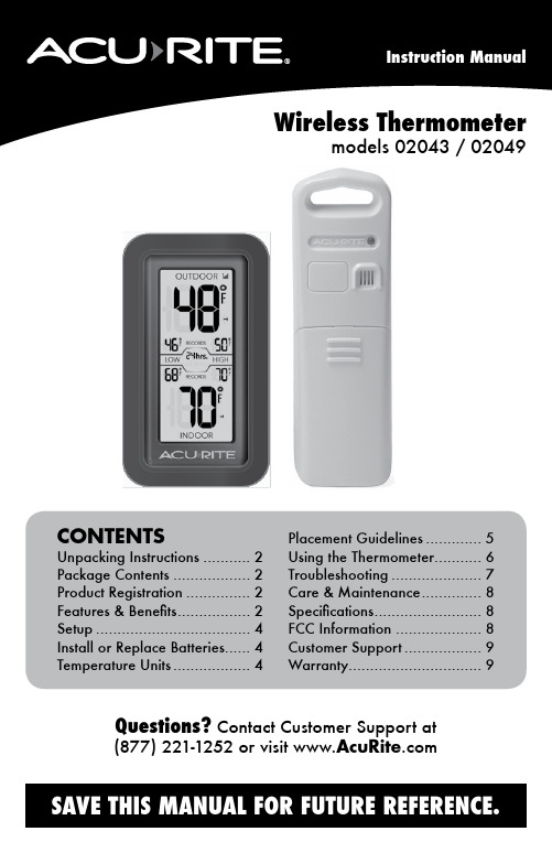
CONTENTS Unpacking Instructions (2)Package Contents (2)Product Registration (2)Features & Benefits (2)Setup (4)Install or Replace Batteries (4)Temperature Units (4)Placement Guidelines (5)Using the Thermometer (6)Troubleshooting (7)Care & Maintenance (8)Specifications (8)FCC Information (8)Customer Support (9)Warranty (9)Wireless Thermometermodels 02043 / 02049Questions? Contact Customer Support at (877) 221-1252 or visit Congratulations on your new AcuRite product. To ensure the best possible product performance, please read this manual in its entirety and retain it for future reference.Unpacking InstructionsRemove the protective film that is applied to the LCD screen prior to using this product. Locate the tab and peel off to remove.Package Contents1. Display unit2. Outdoor sensor3. Instruction ManualFeatures & BenefitsOUTDOOR SENSOR1. Integrated Hanger For easy placement.2. Wireless Signal Indicator Flashes when data is beingsent to the display unit.3. Battery Compartment Cover132DISPLAY UNIT1. S ensor Low Battery Indicator2. C urrent Outdoor Temperature Arrow icon indicates the direction thetemperature is trending.3.R ecord TimespanIndicates viewing records for past 12 hours, 24 hours, 36 hours, 48 hours, or all-time.4. LOW Temperature RecordsLowest temperatures recorded for #3.5. C urrent Indoor TemperatureArrow icon indicates the direction thetemperature is trending.6. D isplay Low Battery Indicator7. H IGH Temperature RecordsHighest temperatures recorded for #3.8. O utdoor Sensor Signal StrengthBACK OF DISPLAY UNIT9. RECORDS ButtonPress to cycle through records (#3).10. Battery Compartment 11. °C/°F ButtonPress to select °C or °Ftemperature units.12. Integrated HangerFor easy placement.Features & Benefits12356478101112Front of Display UnitBack of Display Unit°C/°FInstall or Replace BatteriesAcuRite recommends high quality alkaline batteries for the best product performance. Heavy duty or rechargeable batteries are not recommended.The outdoor sensor requires lithium batteries in low temperature conditions. Cold temperatures can cause alkaline batteries to function improperly. Use lithium batteries in the outdoor sensor for temperatures below -4ºF / -20ºC.Outdoor Sensor1. S lide off the battery compartment cover.2. I nsert 2 x AA batteries into the battery compartment, as shown. Follow the polarity (+/-) diagram in the battery compartment.3. R eplace the battery cover.Display Unit1. S lide off the battery compartment cover.2. I nsert 2 x AA batteries into the battery compartment, as shown. Follow the polarity (+/-) diagram in the battery compartment.3. R eplace the battery cover.Select Temperature UnitsTo select between degrees Fahrenheit (ºF) or Celsius (ºC) temperature units,press the “ºC/ºF” button located inside the battery compartment of the display.batteries properly. Only batteries of the same or equivalent type as recommended are to be used. DO NOT incinerate used batteries. DO NOT dispose of batteries in fire, as batteries may explode or leak. DO NOT mix old and new batteries or types of batteries (alkaline/standard). DO NOT use rechargeable batteries. DO NOT rechargenon-rechargeable batteries. DO NOT short-circuit the supply terminals.°C/°FR E C O R D S - h o l d t o c l e a rPlacement for Maximum AccuracyAcuRite sensors are sensitive to surrounding environmental conditions. Proper placement of both the display unit and outdoor sensor are critical to the accuracy and performance of this product.Display Unit PlacementPlace the display unit in a dry area free of dirt and dust. Display unit stands upright for tabletop use or is wall-mountable.Outdoor Sensor PlacementSensor must be placed outside to observe outdoor conditions. Sensor is water resistant and is designed for general outdoor use, however, to extend its life place the sensor in an area protected from direct weather elements.Hang the sensor using the integrated hang holes or hanger, or by using string (not included) to hang it from a suitable location, like a well covered tree branch. The best location is 4 to 8 feet above the ground with permanent shade and plenty of fresh air to circulate around the sensor.Important Placement Guidelines• To ensure accurate temperature measurement, place units out of directsunlight and away from heat sources or vents.• Display unit and outdoor sensor must be within 165 ft (50 m) of each other. • To maximize wireless range, place units away from large metallic items, thick walls, metal surfaces, or other objects that may limit wireless communication.• To prevent wireless interference, place both units at least 3 ft (.9 m) away from electronic devices (TV, computer, microwave, radio, etc.)Setup is CompleteThe sensor will now synchronize with the display unit. It may take a few minutes for synchronization to complete. Please refer to the troubleshootingsection of this manual if anything appears to be functioning improperly.(50 meters)(165 feet maximum)AT LEAST APARTUsing the ThermometerHigh & Low RecordsThe display will automatically cycle through the high and low recorded values for the past 12 hours, 24 hours, 36 hours, 48 hours, and all-time. To manually cycle through the records, press and release the RECORDS button located in the battery compartment. After 12 seconds of inactivity, the records will return to auto mode.All-time high & low records reflect the minimum and maximum temperature recorded since the unit was powered on, since the batteries were changed, or since it was manually reset (whichever was most recent).To manually reset the high/low records currently being viewed, press and HOLD the RECORDS button, located in the battery compartment for 3-5 seconds.Care & MaintenanceDisplay Unit CareClean with a soft, damp cloth. Do not use caustic cleaners or abrasives. Keep away from dust, dirt and moisture. Clean ventilation ports regularly with a gentle puff of air.Outdoor Sensor CareClean with a soft damp cloth. Do not use caustic cleaners or abrasives.SpecificationsTEMPERATURE RANGE Outdoor: -40ºF to 158ºF; -40ºC to 70ºCIndoor: 32ºF to 122ºF; 0ºC to 50ºCWIRELESS RANGE165 ft / 50 m depending on home construction materials WIRELESS FREQUENCY433 MHzPOWER Display: 2 x AA alkaline batteriesSensor: 2 x AA alkaline or lithium batteriesDATA REPORTING30 second updatesFCC InformationThis device complies with part 15 of FCC rules. Operation is subject to the following two conditions:1- This device may NOT cause harmful interference, and2- This device must accept any interference received, including interference that may cause undesired operation. WARNING: Changes or modifications to this unit not expressly approved by the party responsible for compliance could void the user’s authority to operate the equipment.NOTE: This equipment has been tested and found to comply with the limits for a Class B digital device, pursuant to Part 15 of the FCC rules. These limits are designed to provide reasonable protection against harmful interference in a residential installation. This equip-ment generates, uses and can radiate radio frequency energy and, if not installed and used in accordance with the instructions, may cause harmful interference to radio communications. However, there is no guarantee that interference will not occur in a particular installation. If this equipment does cause harmful interference to radio or television reception, which can be determined by turning the equipment off and on, the user is encouraged to try to correct the interference by one or more of the following measures:• Reorient or relocate the receiving antenna.• Increase the separation between the equipment and the receiver.• Connect the equipment into an outlet on a circuit different from that to which the receiver is connected.• Consult the dealer or an experienced radio/TV technician for help.NOTE: The manufacturer is not responsible for any radio or TV interference caused by unauthorized modifications to this equipment. Such modifications could void the user authority to operate the equipment.This device complies with Industry Canada licence-exempt RSS standard(s).Operation is subject to the following two conditions:(1) This device may not cause interference, and(2) This device must accept any interference received, including interference that may cause undesired operation of the device.At AcuRite, we proudly uphold our commitment to quality technology. Chaney Instrument Co. warrants that all products it manufactures to be of good material and workmanship, and to be free of defects when properly installed and operated for a period of one year from the date of purchase.We recommend that you visit us at for the fastest way to register your product. However, product registration does not eliminate the need to retain youroriginal proof of purchase in order to obtainwarranty benefits.Chaney Instrument Co. warrants that all products it manufactures to be of good material and workmanship, and to be free ofdefects when properly installed and operated for a period ofone year from the date of purchase. Remedy for breach of thiswarranty is limited to repair or replacement of the defectiveitem(s). Any product which, under normal use and service, isproven to breach the warranty contained herein within ONEYEAR from date of sale will, upon examination by Chaney,and at its sole option, be repaired or replaced by Chaney.Transportation costs and charges for returned goods shallbe paid for by the purchaser. Chaney hereby disclaims allresponsibility for such transportation costs and charges. Thiswarranty will not be breached, and Chaney will give no credit for products it manufactures which have received normal wear and tear, been damaged (including by acts of nature), tampered, abused, improperly installed, damaged in shipping, or repaired or altered by others than authorized representatives of Chaney.The above-described warranty is expressly in lieu of all other warranties, express or implied, and all other warranties are hereby expressly disclaimed, including without limitation the implied warranty of merchantability and the implied warranty of fitness for a particular purpose. Chaney expressly disclaims all liability for special, consequential or incidental damages,whether arising in tort or by contract from any breach of thiswarranty. Some states do not allow the exclusion or limitationof incidental or consequential damages, so the above limitation or exclusion may not apply to you. Chaney further disclaims all liability from personal injury relating to its products to the extentpermitted by law. By acceptance of any of Chaney’s products, the purchaser assumes all liability for the consequences arisingfrom their use or misuse. No person, firm or corporation is authorized to assume for Chaney any other liability in connection with the sale of its products. Furthermore, no person, firm or corporation is authorized to modify or waive the terms of this paragraph, and the preceding paragraph, unless done in writing and signed by a duly authorized agent of Chaney. This warranty gives you specific legal rights, and you may also have other rights which vary from state to state.For in-warranty claims: Chaney Instrument Co. 965 Wells St., Lake Geneva, WI 53147Limited One Year WarrantyCustomer SupportAcuRite customer support is committed to providing you with best-in-class service. For assistance , please have the model number of this product available and contact us in any of the following ways:(877) 221-1252 ********************24/7 support at www.AcuRite .com► Installation Videos ► Register your Product ► Instruction Manuals ► Support User Forum ► Replacement Parts► Submit Feedback & Ideas11©Chaney Instrument Co. All rights reserved. AcuRite is a registered trademark of the Chaney Instrument Co., Lake Geneva, WI 53147. All other trademarks and copyrights are the property of their respective owners. AcuRite uses patented technology.Visit /patents for details.Printed in China 02043 INST 121714It’s more than accurate, it’sAcuRite offers an extensive assortment of precision instruments, designed to provide you with information you can depend on toPlan your day with confidence ™.www.AcuRite .comWeather Stations Temperature & Humidity Weather Alert Radio Kitchen Thermometers & Timers Clocks。