HullOFOD8eSolutionsCh09
Weller DS80 解液头及配件说明书

WELLER DS80 ENTLOETKOPFM a t r i x■■■WAD 101WDD 81V WMD 1WMD 32WDD 161VW e l l e r M u l t i -D i g i t a l R e w o r k S t a t i o n W M D 3(W i t h I n -B u i l t P u m p )Weller WMD 3 state-of-the-art technology simultaneously provides multi-digital processor that infinitely controls each tool’s set temperature and airflow.WELLER WMD 3Lock-out key for set functionparameters of each channel.Channel selectorfor temperature and air volume.Timer/set back.Vacuum connectorwith filter cartridge.Connector forhot air pencil withfilter cartridge.other variable combinations.Multi-digital display shows the set air pencil or other connectable tools.Manometer forvacuum control.Antistatic coating onhousing meets ESD safe-ty specifications.Two connections for twooptional foot switches.Mains switch.3W e l l e r M u l t i -D i g i t a l R e w o r k S t a t i o n W M D 1A(W i t h I n -B u i l t P u m p )Mains switch.Vacuum connector and filter cartridge.Hot air nozzles. Different inter-changeable types available.HAP 1 Hot air pencil.Air connector for hot air pencil.Holder KH27 forHAP 1 ho tairpencil.Antistatic coating on housing meets ESD safety specifications.Seven-pin connector forall desoldering, solderingand accessory tools.Temperature and hot air control.Manometer forvacuum control.Connection foroptional foot switch.Socket for potential balance.Pilot light showingheating pulses.4Multi-digital display showsthe set and read temperatureof each tool and air volume.W e l l e r M u l t i -D i g i t a l R e w o r k S t a t i o n W M D 1D(W i t h I n -B u i l t P u m p )Mains switch.Pilot light showing heating pulses.Seven-pin connector forall desoldering, soldering and accessory tools.Manometer for vacuum control.ESD specifications.Connection for optional foot switch.DSX 80, 24V Desoldering ironwith 80W heating element.'Longlife' tiplets.Different interchangeabletypes available.5Temperature and hotair control.Holder AK 20 forDSX 80 desoldering iron.Vacuum connectorand filter cartridge.W e l l e r M u l t i -F u n c t i o n a l , D i g i t a lD e s o l d e r i n g S t a t i o n W D D 161VIt features a micro processor controlled sys-tem which allows independent tempera-display switchable between tools. By use of the WCB1 and WCB 2 control boxes, addi-Weller WDD 161Vhousing meets ESD safetySeven-pin connector forconnecting the DSX andother soldering tools.LED showingheating pulses.the set and read temperatureof DSX 80 or other connected tool.Connector for vacuum Connector for potential balance WSP 80 soldering pencil.“Longlife”tiplets. Differentinterchangeable typesFinger switch to control vacuum.DSX 80 Desoldering iron.Holder WPH 80 forsoldering pencil WSP 80.desoldering iron.Automatically recognizes the DSX 80and other connected tools and sets theappropriate control parameters.W e l l e r M u l t i -F u n c t i o n a l , D i g i t a lD e s o l d e r i n g S t a t i o n W D D 81VMulti-digital display shows the set and read temperature of the DSX 80or other connected tool.DSX 80 Desoldering iron.Finger switchto control vacuum.Microprocessor controlled channel.Automatically recognizes the DSX 80and other connected tools and sets theappropriate control parameters.Connector for vacuum.Seven-pin connector forconnecting the DSX andother soldering tools.Mains switch.Pilot light showingheating pulses.7Antistatic coating on housingmeets ESD safety specificationsHolder AK20 forDSX 80 desoldering iron.“Longlife”tiplets. Differentinterchangeable typesavailable.Connector for potentialbalance8W e l l e r M u l t i -F u n c t i o n a l , D i g i t a lD e s o l d e r i n g S t a t i o n W D D 81V I LMulti-digital display shows the setand read temperature of the DSX 80or other connected tool.DSX 80 Desoldering iron.Finger switchto control vacuum.Microprocessor controlled channel.Automatically recognizes the DSX 80and other connected tools and sets the appropriate control parameters.Connector for vacuum.Seven-pin connector forconnecting the DSX andother soldering tools.Mains switch.Pilot light showingheating pulses.Antistatic coating on housingmeets ESD safety specificationsHolder AK20 forDSX 80 desoldering iron.“Longlife”tiplets. Differentinterchangeable typesavailable.Connector for potential balance9W e l l e r M u l t i -F u n c t i o n , D i g i t a l H o t A i rS t a t i o n W A D 101Multi-digital displaysets and readstemperature of theselected toolHAP 1 Hot air pencilFinger switch tocontrol air manuallyHolder KH27 for HAP 1 ho tair pencil Connector forhot air Seven-pin connector for connecting the HAP 1 and other soldering tools Mains switchAir volume controlPilot light showing heating pulses Antistatic coating on housing meets ESD specificationsMicroprocessor controlled channel.Automatically recognizes the HAP 1and other connected tools and sets the appropriate control parametersHot air nozzles. Differentinterchangeable typesavailableConnector for potentialbalanceWeller Flexibility.Refer to the matrix to make your choice of connecting tools for the WMD 3,WMD 1A + D, WDD 161V , WDD 81V + VIL and WAD 101 (see matrix page 2).HAP 1 Hot air pencilThe HAP 1, 100W/24V, provides a directional hot airflow that is adjustable and static-free. Electronically tempera-ture controlled from 50˚C to 550˚C. Different nozzles available as accessories. Finger switch controls speed adjustable pump. Hot air pencil set, consisting of HAP 1with finger switch, KH 27 Support for pencil, nozzle 1,2and 3,0 mm, key and nutdriver for nozzle changing.HAP 1 5 33 114 99DSX 80 (DS 80 UNC*) Desoldering iron and service kit An 80W/24V desoldering iron for electronics rework.Electronically temperature controlled. Micro-finger switch controls quick-start, fast action vacuum pump.Different interchangeable tiplets, plus several CSFdevices are available as accessories. DS 80 (DS 80 UNC*)set, consisting of DS 80 (DS 80 UNC*) Desoldering iron AK 20 Support, cleaning tool, glass collector, two desoldering nozzles, gasbet, anti-bloc paste, filter.DSX 80 (DS 80 UNC*)5 33 138 99(5 13 191 99)DSX V80 (DS V80 UNC*) Desoldering ironConnectable to all 80W desoldering stations. Handle utilizes the tin collector to hold the extracted solder. Easy to clean by use of the bayonet fitting. DSX V80 set,consisting of DSX V80 Desoldering iron, AKV Support for iron.DSX V80 (DS V80 UNC*)5 33 137 99 (5 33 129 99)DS VT80 Desoldering ironThe model DS VT80 heats up Weller CSF desoldering heads and is equipped with a spring-loaded vacuum pipette, which makes this tool ideal for rework of larger SMD components. DS VT80 set, consisting of DS VT80Desoldering iron, AK V Support for iron.DS VT805 33 134 99LR 21 Antistatic soldering pencilElectronically temperature controlled 50W/24V soldering pencil. LR 21 set, consisting of LR 21 Antistatic soldering pencil, KH 20 Support for pencil.LR 21 5 33 112 99LR 82 Antistatic soldering ironAn 80W/24V soldering iron for high mass soldering. Dual sensor, electronically temperature controlled. LR 82 set,consisting of LR 82 Antistatic soldering iron, KH 27 Support for iron.LR 82 5 33 113 99WSP 80 Micro soldering pencilA micro soldering pencil, 80W/24V. This soldering pencil can be universally used in all situations from extremely delicate soldering to those where there is a greater temperature requirement. WSP 80 set, consisting of WSP 80 Micro soldering pencil with WPH 80 Support.WSP 80 5 29 161 99WSP 1505 33 135 99The WSP 150, 150W/24V, soldering iron was specially developed for soldering tasks with extremely high heat requirements. The 150 W heater power combined with optimal transfer of heat to the soldering iron bit guaran-tee the high performance capability of the soldering iron. WSP 150 set, consisting of WSP 150 Soldering iron,KH 27 Support for iron.WSP 150 Soldering iron*UNC. For use with nozzles with an inch thread.10MLR 21 Micro soldering pencilA micro soldering pencil, 25W/24V with antistatic cord,suitable for miniature soldering work. Electronically temperature controlled. MLR 21 set, consisting ofMLR 21 Micro soldering pencil, KH 15 Support for pencil.MLR 215 33 111 99MPR 80 Antistatic Peritronic soldering pencilAn 80W Antistatic Peritronic soldering pencil that gives all-round vision when making intricate connections.Antistatic cord and handle. Electronically temperature controlled. Consists of MPR 80 Antistatic and KH 25P Support.WMP Micro soldering pencilThe 65W micro pencil is up to the task with superior per-formance for both heat-up and thermal efficiency.Suitable to handle all micro components and fine pitch tasks. The WMP provides an extremely short tip-to-grip distance. The heater is integrated into the handle. When the tip wear out the heating element goes on. WMP set consisting of WMP micro soldering pencil and WPHM holder for WMP .WST 20 Thermal wire stripper with supportThe WST 20, 50W/24V, copes with all known thermoelas-tic plastics. Adjustable for a stripping length up to 30mm.Additional blades available for stripping flat cables and shrinking.WHP 80 (80W/24V) Preheating plateWith a heating surface of 80 x 50 mm, they preheat IC boards prior to micro rework.WHP 80 5 27 028 99WTA 50 TweezerThis tweezer is used to desolder SMD components. The tweezer has two moveable heating elements.WTA 50 set, consisting of WTA 50 Tweezer, AK 51Support for Tweezer.WSB 80 Solder bathThe WSB 80 is a very useful rework preparation tool.The solder bath is temperature controlledcontinuously from 50˚C to 450˚C via an existing 80W power source. The solder bath can be used to tin wire ends and clean leads of all extraneous solder particles in preparation for reworking.WSB 805 27 040 99WTA 50 5 33 133 99MPR 80 5 33 131 99WMP5 33 155 99WST 205 25 030 99WCB 1, WCB 2 Calibration unitsThe intelligence of the digital Weller units can be further enhanced by being programmed by either the WCB 1 or WCB 2 Calibration unit. Both the WCB 1 and the WCB 2 feature temperature lock-out and off-set capabilities up to +40˚C. The WCB 2has the added ability to PC interface (RS 232)and a thermoelement type K and measuring tip.WCB 1 5 31 181 99WCB 2 5 31 180 9911(mm) x y 1(mm)> x + 0,3> y + 0,3CSF-Head Order No.C S F A c c e s s o r i e sRubber insert (spare)Adaptor for DS VT80Adaptor for DS 80, DS V8012,0 x 12,0 5 87 417 33 5 87 417 88 5 87 417 15 5 87 417 84 5 87 418 03 5 87 137 9912,0 x 14,5 5 87 417 34 5 87 417 88 5 87 417 15 5 87 417 84 5 87 418 0312,7 x 12,7 5 87 417 35 5 87 418 035 87 418 0412,7 x 12,7 5 87 417 396 5 87 417 88 5 87 417 15 5 87 417 84 5 87 418 03 5 87 137 9917,8 x 17,8 5 87 417 4011 5 87 417 89 5 87 417 16 5 87 417 85 5 87 418 04 5 87 137 9820,4 x 20,4 5 87 417 4116 5 87 417 90 5 87 417 17 5 87 417 86 5 87 418 05 5 87 137 9825,4 x 25,4 5 87 417 4216 5 87 417 90 5 87 417 17 5 87 417 86 5 87 418 05 5 87 137 9830,4 x 30,4 5 87 417 4316 5 87 417 90 5 87 417 17 5 87 417 86 5 87 418 05 5 87 137 985,5 x 10,0 5 87 417 236 5 87 417 88 5 87 417 15 5 87 417 84 5 87 418 03 5 87 137 995,8 x 10,5 5 87 417 246 5 87 417 88 5 87 417 15 5 87 417 84 5 87 418 03 5 87 137 996,7 x 10,0 5 87 417 256 5 87 417 88 5 87 417 15 5 87 417 84 5 87 418 03 5 87 137 999,3 x 13,0 5 87 417 266 5 87 417 88 5 87 417 15 5 87 417 84 5 87 418 03 5 87 137 999,4 x 10,0 5 87 417 276 5 87 417 88 5 87 417 15 5 87 417 84 5 87 418 03 5 87 137 999,8 x 18,0 5 87 417 286 5 87 417 88 5 87 417 15 5 87 417 84 5 87 418 03 5 87 137 9910,0 x 16,0 5 87 417 296 5 87 417 88 5 87 417 15 5 87 417 84 5 87 418 03 5 87 137 9910,5 x 16,0 5 87 417 306 5 87 417 88 5 87 417 15 5 87 417 84 5 87 418 03 5 87 137 9910,7 x 18,0 5 87 417 316 5 87 417 88 5 87 417 15 5 87 417 84 5 87 418 03 5 87 137 9911,0 x 26,5 5 87 417 3211 5 87 417 89 5 87 417 16 5 87 417 85 5 87 418 04 5 87 137 98for DS 80 (DS 80 UNC),DSX 80, DS V80 (DS V80 UNC), DSX V80 and DS VT80 for SMD’s chip desoldering tiplets for flat packsSOJ-Case9,0 x 18,0 5 87 417 446 5 87 417 88 5 87 417 15 5 87 417 84 5 87 418 03 5 87 137 99CSF-QlCSF-DCSF-DlAdaptor for DS 80 UNC, DS V80 UNC12Adaptor for DSX80, DSX V80A c c e s s o r i es0,7230,723For easier rework and repair, Weller has a large range of desolderingnozzles and soldering tips.Nozzles for desolderingiron DSX 80 andDSX V80:mm mm13Threadless nozzles for desoldering iron DSX 80 und DSX V80The new X series nozzle feature a threadless fixture system wherebythe nozzle is inserted into the head and locked into place by apllyinga 1/4 turn. This feature allows the nozzles to be quickly and easilyexchanged and also improves the rate of thermal transfer from thehead to the nozzle.H o t A i r N o z z l e sfor hot air pencil HAP 1No.Description Dimensions Type Order(mm)14Description Dimensions Type Order No.H o t A i r N o z z l e sfor hot air pencil HAP 11516for soldering iron LR 82DescriptionWidth A Thickness B T ype Order No.ABABABAABABBfor soldering pencil LR 21Description Width T ype Order No. for Order No. forregular solder HPB solderLong screwdriver tipRound tip, bluntSloped round tipConical long tipScrewdriver tipFlat tip, slightly bent,one side wettable onlyChip soldering/desoldering tipSoldering tip for J-LeadsSoldering tip for GullwingsET Calibration nozzle17Description Width T ype Order No.for soldering pencil MLR 211819For micro soldering pencil WMPDescription Width A Thickness B Length C T ype / Order No.Description Width A Thickness B T ype Order No.Order No.Order No.regular solder HPB solderlead free solderfor WSP 80, WSP 80 FE and MPR 8020Description Width A Thickness B T ype Order No.regular solderfor WSP 80, WSP 80 FE, MPR 8021S o l d e r i n g T i p sFor WT 50 and WTA 50 tweezer22Description Width A Thickness B Type Order No.For soldering iron WSP 15023Additional Support, and Holders5 15 012 99WPHM5 15 010 995 15 140 995 15 042 99 5 15 019 995 15 038 995 15 020 995 15 027 995 15 033 995 15 030 99AK 1Support for DSX 80 (DS 80 UNC)Desoldering iron, HAP 1 Hot air pen-cil, LR 21 and LR 82 Antistatic solder-ing pencilsKH 27 Support for LR 82 Soldering iron, HAP 1 and WSP 150AK V Support for DS VT80 and DSX V80 (DS V80 UNC) Desoldering ironKH 25P Support for MPR 80 Peritronic soldering pencil AK 51Support for WTA 50 TweezerWPH 80Support for WSP 80 Micro soldering pencilWPHM support for WMP micro sol-dering pencil AK 21Support for MPR 80 Peritronic soldering pencil AK 20 Support for DSX 80 (DS 80UNC) Desoldering iron and HAP 1Hot air pencilKH 15Support for MLR 21 Micro soldering pencilKH 20Support for LR 21 Antistatic soldering pencil and HAP 1 Hot air pencilConsists of:■Power unitOrder No.: 5 33 026 99(UK: 5 33 023 99)Consists of:■Power unit WMD 1S 5 33 286 99(UK: 5 33 283 99)■Hot air pencil HAP 1 5 27 115 99■Holder KH 27 5 15 027 99■Nozzle R 04 5 87 278 21■Nozzle R 06 5 87 278 22■Cleaning set 5 13 500 99Order No.: 5 33 306 99(UK: 5 33 303 99)Consists of:■Power unit■Hot air pencil HAP 1 5 27 115 99■Holder KH 27 5 15 027 99■Nozzle R 04 5 87 278 21■Nozzle R 06 5 87 278 22■Cleaning set 5 13 500 99Order No.: 5 32 666 99(UK: 5 32 663 99)Consists of:■Power unit WMD 1S 5 33 286 99(UK: 5 33 283 99) ■Desoldering iron DSX 80 5 13 190 99■Holder AK 20 5 15 030 99■Nozzle DX 112 5 13 142 99■Nozzle DX 113 5 13 150 99■Cleaning set 5 13 500 99■Replacement glass tube 5 13 605 00Order No.: 5 33 326 99(UK: 5 33 323 99)Consists of:■Power unit PUDD 161V 5 32 886 99(UK: 5 32 883 99)■Desoldering iron DSX 80 5 13 190 99■Soldering pencil WSP 80 5 29 161 99■Holder AK 20 5 15 030 99■Holder WPH 80 5 15 146 99■Nozzle DX 112 5 13 142 99■Nozzle DX 113 5 13 150 99■Cleaning set 5 13 500 99■Replacement glass tube 5 13 605 00Order No.: 5 32 806 99(UK: 5 32 803 99)Consists of:■Power unit PUDD 81V 5 32 586 99(UK: 5 32 583 99)■Desoldering iron DSX 80 5 13 190 99■Holder AK 20 5 15 030 99■Nozzle DX 112 5 13 142 99■Nozzle DX 113 5 13 150 99■Cleaning set 5 13 500 99■Replacement glass tube 5 13 605 00Order No.: 5 32 566 99(UK: 5 32 563 99)Consists of:■Power unit PUDD 81V 5 32 586 99(UK: 5 32 583 99)■Inline desolderingiron DSX V80 5 13 197 99■Holder AK V 5 15 038 99■Nozzle DX 112 5 13 142 99■Nozzle DX 113 5 13 150 99■Cleaning set 5 13 500 99Order No.: 5 32 546 99(UK: 5 32 543 99)WELLER DS80 ENTLOETKOPF。
艾迪沃德指纹产品资料(NEW)

指纹考勤机 J7NU(ARM9)NEW艾迪沃德最新产品,精美外观,得体大方. 运用最先进的第八代指纹识别技术,指纹容量10000枚(3万 5万可选)指纹算法突破极限,单处理器可比对50000枚/秒。
接受干湿指纹,更加完善的功能主要表现在:系统稳定的,操作方性都有所提高,尤其指纹识别速度大大提高。
参数J7NU(ARM9)比对方式1:N ;1:1指纹容量10000枚响应时间≤1.2秒(注册满10000枚)认假率(FAR)≤0.0001%据真率(FRR)≤0.01% 安全等级1:N 1-4可设置1:1 0-50可设置记录容量管理1000条考勤80000条认证方式指纹、密码、IC卡(身份证,公交卡)工作方式脱机数据传输距离1200m(RS485)语音提示中文、英文、蜂鸣器提示LCD显示中文、英文、人名显示指纹输入面积18mm×16mm输入电压220V AC工作电压、功耗5V DC 小于5瓦抗静电强度<15KV体积155mmX210mmX50mm配置标准考勤机、RS232数据线、外接电源、考勤软件、TCP/IP(广域网)、U盘下载、USB选件232/485转换器精美外观,得体大方. 运用最先进的第七代指纹识别技术。
接受干湿指纹,更加完善的功能主要表现在:系统稳定的,操作方性都有所提高,尤其指纹识别速度大大提高。
同时我们可以接受ODM/OEM合作。
参数J8NU比对方式1:N ;1:1指纹容量2000枚响应时间≤1.2秒(注册满2000枚)认假率(FAR)≤0.0001%据真率(FRR)≤0.01% 安全等级1:N 1-4可设置1:1 0-50可设置记录容量管理1000条考勤50000条认证方式指纹、密码工作方式脱机数据传输距离1200m(RS485)语音提示中文、英文、蜂鸣器提示LCD显示中文、英文、人名显示指纹输入面积18mm×16mm输入电压220V AC工作电压、功耗5V DC 小于5瓦抗静电强度<15KV体积155mmX210mmX50mm配置标准考勤机、RS232数据线、外接电源、考勤软件、TCP/IP、U盘下载选件232/485转换器艾迪沃德最新产品,集经典外观与强大功能与一身。
KDA8路全隔离热电偶采集模块使用说明书
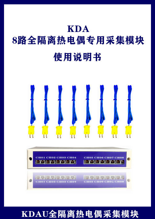
KD AA: 全隔离信号(0.1秒采样)C: 通用隔离输入E: 4-20mA专用输入G: 单热电偶全隔离输入H: 单热电偶非隔离输入J: 隔离输入支持 10A电流输入K: 隔离输入(独立馈电接线)M: 标准信号(独立馈电接线)U: 单热电偶全隔离输入(热电偶专用插头)7-24V 6通道工作电源最大输入7-24V 12通道7-24V7-24V16通道16通道7-24V7-24V16通道6通道7-24V7-24V7-24V8通道8通道8通道RS485输出接口RS485RS485RS485RS485RS485RS485RS485RS485产品尺寸: 187(W)X34(H)mmX112(D)mm 导轨安装或桌面放置KD BA: 全隔离信号(0.1秒采样) B: 标准信号 (0.3秒采样)C: 通用隔离输入D: 经济型标准输入E: 4-20mA专用输入G: 单热电偶全隔离输入H: 单热电偶非隔离输入J: 隔离输入支持 10A电流输入7-24V7-24V6通道6通道工作电源最大输入7-24V7-24V6通道6通道7-24V7-24V6通道8通道7-24V7-24V8通道6通道RS485RS485输出接口RS485RS485RS485RS485RS485RS485产品尺寸: 93(W)X35(H)mmX121(D)mm 导轨安装或桌面放置KD CE: 4-20mA专用输入H: 单热电偶非隔离输入7-24V7-24V1通道1通道工作电源最大输入RS485RS485输出接口产品尺寸: 54(W)X32(H)mmX82(D)mm 导轨安装或桌面放置输入信号选型附表U: 单热电偶全隔离输入(热电偶专用插头)U注 C系列信号板与A系列信号功能接近,C系列信号板不支持NTC输入,不支持0-50V输入C系列热电偶冷端精度为正负0.1度,而A系列冷端精度则为正负0.5度(影响热电偶绝对误差)C系列信号板侧重于热电偶精度,而A系列侧重于兼容性,抗干扰能力区别不大,均为隔离差分186mm前视图后视图186mm34m mR S 485转U S B 通讯接口上图为了看清接线,USB 被放大了,非实物比例在电脑上按装U 盘里的驱动复制电脑在线监控系统到电脑上如果是无线模块,已接好线,分别插在仪表上与电脑上如果是布线的将仪表的485+接转换器直接将热电偶插头插入每个通道B A 24V (不分正负极)-485+模块供电CH01 CH02CH03 CH04CH05 CH06CH07 CH08热电偶插头热电偶插头0008050301ST E J K -200.0~1300.0-200.0~800.0-200.0~1000.0-200.0~400.0-50.0~1650.0输入代码SN 与信号类型接上电源,通过485通讯连接到电脑或PLC 或人机界面 连电脑时我们有配套的监控软件 一台电脑或人机界面可以接64个模块 每个模块可以设置不同的地址或波特率RS48安装软件在电脑上按装盘里的驱动341复制电脑在线监控系统到电脑上如果是无线模块,已接好线,分别插在仪表上与电脑上315转USB 通讯接口24RS 485转US B 通讯接口接仪表RS 485+接仪表RS 485-1台电脑可监控20台无纸记录仪,最大多可达255测试点仪表连接电脑后,扫描电脑二维码,可通过手机远程监控电脑监控软件免费,一台电脑需要一个可根据实际定制电脑上位机软件接仪表RS 485+接仪表RS 485-自定义通道名称及单位名称 上下限电脑报警查询数据只需0.1秒 高速而稳定同时显示所有通道曲线 曲线放大 坐标位移功能视频教程 高效而稳定的上位机软件研发费用至少在数百万元之上无疑给成长中仪器仪表厂商带来困惑;为此科顺仪器愿将上位机软件共享给仪器仪表厂商使用;软件可永久授权软件并提共源代码;具有完全自主知识产权;自绘数据显示控件, 自主研发实时数据库,极小体积;可导出EXCEL软件仅供我司仪器仪表用户免费使用,不支持第三方硬件商业授权主要面向仪器仪表厂商即仪器仪表厂商生产的仪表或采集模块使用我们的软件来监控商业授权提供三年以上技术支持,并提供驱动开发;商业授权提供10种硬件驱动开发,并提供软件所有源码;为我司模块提供量程上下限配置设置模块输入类型如 4-20mA 0-5V Pt100等模块误差修正功能等视频教程 读测量值功能码寄存器地址寄存器说明0400-151~16通道温度值数据类型INT16功能码寄存器地址寄存器说明数据类型读内部寄存器0300-15返回通道1-16mV 值INT160316-311~16通道温度值INT1603254仪表类型INT1603255环境温度INT160332-471~16通道传感器输入类型表INT160348-631-16通道传感器误差修正值INT160364-791~16通道K 型热电偶温度值INT160380-951~16通道E 型热电偶温度值INT160396-1111~16通道N 型热电偶温度值INT1603112-1281~16通道J 型热电偶温度值INT1603128-1431~16通道Wre 3-25热电偶温度值INT1603144-1591~16通道T 型热电偶温度值INT1603160-1751~16通道B 型热电偶温度值INT1603175-1911~16通道R 型热电偶温度值INT1603192-2071~16通道S 型热电偶温度值INT1603208-2231~16通道Wre 5-26热电偶温度值INT1603224-2401~16通道F2型热电偶温度值INT1603253通讯地址INT1603252波特率INT16通讯协议模块适用于标准Modbus RTU 通讯协议,仪表支持下文中所描述的功能码。
美еред Model AM8e:调用分析器技术数据书说明书

IntroductionWhether you are a telecommunications service provider or a telecommunications equipment manufacturer, the global market-place has requirements for a multitude of signaling protocols within countries and between countries.In-service circuits need troubleshooting. New products need testing and, eventually, manufac-turing test and field support. Until now, the only solution may have been numerous test instru-ments or expensive in-house test equipment development for each country or application.The Ameritec Model AM8e is a Call Analyzer capable of emulating, observing and trouble-shooting signaling protocols on a wide variety of analog circuits or 2 Mbps channel associated signaling PCM circuits. The AM8e is user programmable. You can modify existingsignaling protocols or develop new signalingprotocols based on your requirements. 2 Mbps PCM Testing The AM8e is compatible with worldwide CCITT recommendations for 2 Mbps, 30-channel, channel associated signaling PCM lines.The unit is compatible with all country specific A, B, C, D bit signaling and MF-R1, MF-R2,CCITT #5, DTMF, and dial pulse protocols.The AM8e provides for emulation and non-intrusive monitoring of 2 Mbps PCM circuits.Specific channels can also be monitored. Also provided is a drop and insert capability which allows testing of individual PCM plete decoding and analysis of MF-R1,MF-R2, CCITT #5, DTMF, and dial pulse signaling is provided. Precise, one-millisecond time stamping of digits and events will tell you exactly what happened and when.Exception reports can be printed by connecting an accessory printer and using the built-in programmable signaling thresholds to automati-cally screen for out of tolerance digits and events.User Programmable Signaling ProtocolsTo provide the utmost in flexibility to accommo-date worldwide signaling variations, the AM8e is protocol driven. Protocols may be purchased from Ameritec’s extensive library, custom developed by Ameritec or developed by the user. The AM8e can store up to 10 complex protocols which can be simply recalled and executed. The protocols allow for various W AIT conditions, such as Wait for 3Seconds, Wait For Call Progress Tone, Wait For Wink and so on. The protocols can select any of the available 10 autodial strings and each string can point to another string for virtually unlimited dialed digit lengths. Calling and called party numbers may be stored in different autodial strings and executed at the appropriate stimulus from within the protocol. Dialing may be dependent upon a Wait condition. These capabilities allow the user to test complex Intelligent Network functions as well as CTI applications such as V oice Mail.Protocols can also cause tones to be transmitted with a specific level and frequency. For dual tone dialing, the level and frequency of each tone of the two tones can be specified, allowing for testing of an application over the full range of specified dialed digit capability. Simple loops can be set up in a protocol for incremental worst case testing. Analog Loop Trunk/Line EmulationThe AM8e is also compatible with two-wire analog type trunks and lines. User programmable emulation, monitoring and analysis are provided for the following parameters:• Battery V oltage, Loop Length & Termination • Start Dial Signals including Dial Tone • MF-R1, DTMF & Dial Pulse Signaling • Dial Pulse Speed, Make/Break & Interdigit Time• MF/DTMF Digit Timing,Twist &Skew • Dial Tone Delay, Cadence,Frequencies & Level • Hookflash & Line Unbalance• Ringing V oltage, Frequency & Cadence • Delay & Wink Start Signals• Single Test Tone Frequency & Level The analysis functions allow measurement thresholds to be set in order to capture erroneous digits and events. This, along with the precise,one-millisecond time stamping of digits and events, allows detection of even the most subtle problems.AM8e with E&M Adapter.AM8e E&M Adapter The AM8e E&M Adapter replaces the protective front panel cover of the AM8e and offers conve-nient access to analog E&M signaling emulation,monitoring, and analysis capabilities. This includes North American standards too! Simply attach the E&M Adapter to the LINE/TIMS Connector of your AM8e with the ribbon cable and you are ready to apply the same troubleshooting and testing power available for PCM and two-wire loop circuits.In combination with the AM8e, the E&M Adapter provides the following analog E&M capabilities:•E&M Signaling Emulator/Monitor/Analyzer •E&M Types I through V , 2-Wire and 4-Wire •4-Wire E&M and 4-Wire Phantom E&M •Programmable Signaling Protocols to Control E&M Leads •Digit Emulator/Monitor/Analyzer (MF-R1, MF-R2, CCITT #5, DTMF, Dial Pulse)•Complex Sequence Dialer •High/Low Thresholds for Capturing Erroneous Digits and Events •Precise, One-Millisecond Time Stamping of Digits and Events •VF Level, Frequency and Noise Measure •CO Battery and Dial Tone Generator Ameritec E&M signaling protocols are available or users may develop their own protocols.T1/E1 Adapter The AM8e T1/E1 Adapter replaces the protec-tive front panel cover of the AM8e. The Adapter converts the AM8e E1 input/output to T1input/output and accommodates both PCM1 and PCM2. With this Adapter the power of the AM8e protocols can be used in a T1 environment to allow test of very complex interface protocols.Additionally, an AM8e with this Adapter can also be used for standard T1 testing, significantly improving the utility and versatility of the AM8e.Off Hook Display Selection for Events or VoltmeterDirect Entry KeypadFar End Start Dial Out of Dialing Digits (Near End)Far End Answer ON/OFF Power ButtonVolume control for speaker Microphone to communicate over circuit under test Connection of telephone handset for private conversations Connection of external Transmission Impairment Measuring Set (such as Ameritec's AM5eXT)• RS232 Port for exception reporting & remote control.• Decoding of MF-R1, MF-R2, CCITT #5, DTMF and dial pulse digits without pre-determination of type.• Built-in Speaker.• Optional Battery Pack for 8 Hours Use Visual LED indicators to show configuration of unit.Near End On Hook Analog Loop Connection2 Mbps PCM span connections Grouping of Direct Function Switches Scrolling up &down pages within each setup menu Scrolling across choices for setup parameters Unit setup including emulation parameters.Analyzer Thresholds and Auto Dial sequences ON/OFF Toggles for connection to Trunk inputs & TIMS.Enable hands-free talk and auto send of start signalDialed MF-R2 Digits each followed by a backward acknowledge digit.Time from off-hook to MF-R2 forward digit 8, level/freq. low tone, level/freq. high tone,and interdigit time/digit duration.Detailed Call AnalysisFar End On Hook Display of A/B signaling bits for all 30 E1 time slots (transmit and receive).Detailed Digit, Event Analysis When connected to a circuit, the unit will display signaling events occurring in either direc-tion on a large backlighted liquid crystal display (LCD). Up to 80 dialed digits and/or events (on hook, off hook, wink, etc.) are collected and displayed for each call.By merely placing a cursor under the digit or event of interest, the operator can observe, on the second line of the display, all details associated with that event. For example, when observing a DTMF digit, the unit will display the time of the digit and its duration, as well as the measured high and low band frequency and level.If the operator had previously entered good/bad thresholds, then any out-of-spec detail would be highlighted to the operator.With each event in a complexsequence captured in detail,troubleshooting becomes a matter of solving the problem instead ofsearching for the problem.Built-in Analog and PCM Testing The ability to measure VF level, frequency and noise on analog circuits and PCM channels is built into the AM8e. For more extensive testing, a TIMS access port is provided.The unit also provides a variety of non-intrusive PCM digital tests including bit and frame slips,CRC errors, and framing errors. A display of all 30 PCM channel A/B signaling bits can also be viewed for the transmit and receive directions.All front panel test ports appear on the rear panel LINE/TIMS connector which simplifies integration into a test system.Complex Sequence Auto-Dialer Through the front panel keypad or via a protocol, the operator can dial any sequence of digits and events either manually or automati-cally. Up to 10 complex dialing sequences can be stored and later recalled for execution under the “autodial” function. One autodial sequence can “point” to another so that a complex dialing routine can effectively be hundreds of events long.For example, the following sequence might be used to initiate test calls from a PABX station and use multiple signaling modes to reach and communicate with specialized equipment.PCM Drop & Insert The AM8e provides two PCM ports with dual receivers andtransmitters.These ports canbe usedforpassivemonitoring of a PCM span or the AM8e may be inserted in series with the PCM span for full duplex drop and insert testing of individual channels.The two PCM ports can also be used for clock synchronization testing of PCM spans where one port is connected to a reference span while the second port is connected to the span under test.Easy Setup Commonly used AM8e test setups can be stored in non-volatile memory for later use. 20 non-volatile memories are available for instant recall of personalized AM8e configura-tion setups. An additional 20 memories are availablefor recall of emulate/analyze parameters. This is in addition to the previouslymentioned memories for 10 auto-dial sequences plus last number redial.High Tech, Small SizeThe AM8e incorporates multiple digital signal processors and microprocessors in a highly compact portable package. The unit may be powered from commercial mains, where it automatically adjusts for compatibility with local line voltage and frequency, or it may be powered from an optional internal rechargeable battery pack. An optional RS232 port and aux port allows for automatic hard copy reporting and remote control. A 24-pin LINE/TIMS connector on the rear of the AM8e provides secondary access to all front panel connections and is useful for perma-nent AM8e installations in systems and other test equipment.Dual PCM ports.Easy setup store and recall.Rear of AM8e with RS232 ports for hard copy output and remote control.Simulated Voice Response System Test CallAM8e shown in rack mount configuration.Built-in VoltmeterA dual multimeter with analog and digital display is provided. AC volts, DC volts, and current measurements may be operator selected for tip to ring, tip to ground or ring to ground connections. PCM signal amplitude can be measured when using the AM8e in PCM mode.Portable or Rack Mount No other signaling test set of this type is as full featured, small and convenient.About the size and weight of a telephone directory, it is easily transported from lab to field. For permanent installations, a rack mounting kit is available which will allow 19" relay rack mounting in only two rack increments (3 1/2”) of space.European Community StandardsThe AM8e is fully certified to meet the safety and emission standards of the EuropeanCommunity. The ce marked version of the AM8e is designated the AM8e (ce).Accessories and Options Provided Model AM8e, removable front cover with storage, power cord, monitor cables and instruc-tion manual.Optional BatteryAn optional internal, rechargeablebattery pack is available for fullyportable "cordless" operation. The batteries are of sealed lead-acid type and require no maintenance. A front panel low battery indicator indicates when recharging is needed.The built-in charger allows thebatteries to be charged even while the unit is in operation.Options30-0056AM8e E&M Adapter 19-0004Protocol Development Kit (softools Assembler/linker & PC required)24-0018Internal Power Pack (Sealed Rechargeable Lead Acid Batteries)andInternal Charger.(included in the AM8e (ce)).85-023319" Rack Mount Shelf.48-0062 6 Ft. Bantam to Clip Input Cable.48-0047 6 Ft. Bantam to Bantam Input Cable.48-0048 6 Ft. Bantam to 310 Input Cable.87-0070Padded Carrying CaseAM8e with manual, cables, cover, and optional soft carrying case.Dual multimeter display showing battery and loop current measurements.AM8e Technical SpecificationsLINE INTERFACESAnalog Loop:Trunk monitor or emulation of either the Switch or Subscriber interface.Digital Circuits (PCM1 or PCM2)2.048 Megabits/second Pulse Code Modulation (PCM). Conforms to CCITT Rec. G.703. Channel Associated Signaling. Two spans (ports) provided to support drop-and-insert channel. Line Coding: HDB3. CRC-4 is selectable.DialingSupports any of these dialing modes with full digit set—1, 2, 3, 4, 5, 6, 7, 8, 9, 0, *, #, A, B, C, and (for DTMF only) D:Dual Tone Multi-Frequency (DTMF)Dial PulseMulti-Frequency-R1 — MF(R1)Multi-Frequency-R2 — MF(R2) (PCM only) CCITT System No. 5Start SignalingImmediate, Wink, Delay Dial, Dial ToneLine SignalingDetects And Generates: On Hook, Off hook, Wink, Flash, Unbalance (generate only), Ring, Reverse BatteryEMULATIONUser-controlled parameters for circuit emulation. When shown as a range, parameters are selec-table in unit steps unless noted.Digital PortsImpedance:75 at 2.048 Megabits/Second, 1575 provided in monitor cable for monitor mode Office BatteryVoltage: 20 V to 72 V ±2%Current: 120 mA maximum (not selectable) Analog LoopDC Loop Length:0 to 2100 , adjustable in 300 steps (At 2100 Loop Length, AM8e cannot detect Ring Trip)DC Hold Resistance:10 , 330 , 430AC Impedance:150 , 600 , 900 , 1200 at 300 to 3300 Hz, 2.16 µF in or out (24 µF) Ringer Load:0.68µF in series with 2K , 2W Ring GenerationVoltage:30 Vrms to 105 Vrms ±4% in 5 Vrms steps (At 2100 Loop Length, AM8e cannot detect Ring Trip)Frequency:15.0 Hz to 70.0 Hz in 0.1 Hz steps Load:5 telephone ringers maximum Cadence:Rings: 1 to 3, individual on/off timers Cadence:On Time: 0 to 5000 msOff Time:0 to 9999 msRing Time:(before thermal shutdown)Minimum: 5 minutes (max load)Typical: 20 minutesCall Progress TonesDial Tone Generation:Low Frequency: 0, or 300 Hz to 3300 HzLow Freq. Level: -40 dBm to -3 dBmHigh Frequency: 0, or 300 Hz to 3300 HzHigh Freq. Level: -40 dBm to -3 dBmCadence: 1 to 3, individual on/off timersCadence On Time: 0 to 9999 msCadence Off Time: 0 to 9999 msStart SignalsWink Begin:15 to 999 msWink Duration:50 to 999 msDelay Begin:15 to 999 msDelay End:100 to 9999 msDial Tone Delay From Seizure:15 to 9999 msDialingPulse Dialing:Speed: 5 to 25 ppsPercent Break: 40% to 85%Interdigit Time: 120 to 999 ms±2msAccuracy at 10 pps: ±0.1pps (40% to 75%break)DTMF:Low Band Frequencies: 697, 770, 852, 941 HzLow Band Offset: -5% to +5%, in 0.1% stepsLow Band Level: -40 dBm to -3 dBmHigh Band Frequencies: 1209, 1336, 1477,1633 HzHigh Band Offset: -5% to +5%, in 0.1% stepsHigh Band Level: -40 dBm to -3 dBmOn Time: 25 to 99 msOff Time: 25 to 99 msMF(R1):Frequencies: 700, 900, 1100, 1300, 1500,1700 HzLow Freq. Offset: -5% to +5%, in 0.1% stepsLow Freq. Level: -40 dBm to -3 dBmHigh Freq. Offset: -5% to+5%, in 0.1% stepsHigh Freq. Level: -40 dBm to -3 dBmOn Time: 25 to 99 msOff Time: 25 to 99 msMF(R2) Forward Signals:Frequencies: 1380, 1500, 1620, 1740, 1860,1980 HzLow Freq. Offset: -5% to +5%, in 0.1% stepsLow Freq. Level: -40 dBm to -3 dBmHigh Freq. Offset: -5% to +5%, in 0.1% stepsHigh Freq. Level: -40 dBm to -3 dBmAcknowledgement Timeout: 40 to 999 msMF(R2) Backward Signals:Frequencies: 540, 660, 780, 900, 1020,1140 HzLow Freq. Offset: -5% to +5%, in 0.1% stepsMF(R2) Backward Signals:Low Freq. Level: -40 dBm to -3 dBmHigh Freq. Offset: -5% to +5%, in 0.1% stepsHigh Freq. Level: -40 dBm to -3 dBmAcknowledgement Timeout: 100 - 9999 msCCITT System No. 5Frequencies: 2400Hz, 2600HzFrequency Offset: -2.0% to 2.0%, in 0.1%stepsLevel: -30 dBm to -3 dBmOn Time: 10 ms min.Tone GenerationFrequency:300 Hz to 3300 HzLevel: -40 dBm to 0 dBmGeneration Accuracy (Unless otherwisespecified)Frequency:± 1 HzLevel:± 1 dBTiming:± 1 msANALYSISUser-controlled threshold parameters for eventdetection. Ranges shown are selectable in unitsteps unless otherwise noted.FlashMinimum On Hook Time:50 to 1250 msDisconnectMinimum On Hook Time:50 to 1250 msCall Progress TonesFirst Frequency:350, 440, 480, or 620 HzSecond Frequency: 350, 440, 480, or 620 HzFrequency Tolerance:±0.2%Minimum Level per Tone:-35 dBm to -3 dBmStart SignalsWink Begin:15 to 999 msWink Duration:50 to 999 msDelay Begin:0 to 999 msDelay End:0 to 9999 msDial Tone Receive:0 to 999 msSpecial Dialing CommandsWait for DialtoneWait for 3 SecondsWait for WinkWait for Unidentified ToneWait for Call Progress ToneWait for Single Frequency ToneWait for AnswerWait for User Defined Event A or BChange Dialing Type(d to DTMF, p toPulse, m to MF R1, r to MFC R2)08 -24-98*- Protection Circuits assume a sourceimpedance >300 to limit current.1- Common mode AC plus DC voltage < 100V peak2- Common mode AC plus DC voltage < 10V peak3- Measurements are displayed as peak voltage atthe RX point.4- Event details display of ringing is 0 to 130Vrms±3%, ±1 Vrms over 0°C - 50°C range.Tone Dialing (DTMF)Frequency Tolerance:0% to 3.5%, in 0.1%steps Accuracy : ±0.2%Level Range per Frequency:-30 dBm to -3 dBm Allowable Twist:-12 dB to +12 dB Minimum On Time:40 ms ±5 ms Minimum Off Time:25 ms ±5 ms Tone Dialing MF (R1)Frequency Tolerance :0 to 3.5%, in 0.1% steps Accuracy : ±0.2%Level Range per Frequency:-30 dBm to -3dBm Allowable Twist:-12 dB to +12 dB Min. On Time:40 ms ±5 ms Min. Off Time:25 ms ±5 ms Tone Dialing MF (R2)Frequency Tolerance:0 to 3.5%, in 0.1% stepsAccuracy:±0.2%Level Range per Frequency: -30 dBm to -3 dBm Allowable Twist:-12 dB to +12 dBMin. On Time:40 ms ±5 msMin. Off Time:25 ms ±5 ms CCITT System No. 5Frequency Tolerance:0 to ±15 Hz Accuracy:±1 Hz Level Range:-30 dBm to -3 dBm Allowable Twist:-10 dB to +10 dB Min. On Time:60 ms ±5 ms Pulse DialingSpeed Range:5 to 25 pulses/secondPercent Break:40% to 85%Accuracy at 10 pps:±0.2pps (40% to 75%break ±2%)Interdigit Time:120 to 999 ms ±5 ms Tone Threshold Level Threshold:-40 dBm to 0 dBm On/Off Hook Threshold Level Threshold:2 to 60 V Accuracy:±3% ±0.7 V Measurement Accuracy (Unless other-wise specified)Frequency:± 1 HzLevel : ± 1 dBTiming:± 2 msGuard Time: 0 to 99 ms (for all tones)METER MEASUREMENTS Analog AC Volts Range:0 to 130Vrms ±2%, ±1Vrms (0°C - 50°C)(DC offset < 75V, crest factor < 1.6) (15 to 75 Hz)Loop Start:Tip-Ring , Tip-Ground , Ring-Ground , Common mode Tip-RingAnalog DC Volts Range:-150V to +150V ±2%, ±1V over 0°C -50°C range Loop Start:Tip-Ring , Tip-Ground , Ring-Ground , Common mode Tip-Ring Analog DC A-lead Loop Current *5 to 180mA ±2%, ±1mA (72 Vdc MAX)Noise (Analog or Selected PCM Channel)Level Range:-40 to 0 dBm ±dBm Frequency Range:300 Hz to 3300 Hz ±1 Hz Filter:Psophometric or Flat (CCITT Rec. 468-2 &J16) (Analog signals are also filtered 300 to 3300Hz by codec.)Analog Loop:Tip-RingPCM1/PCM2:Tx, Rx (selected channel)Tone (Analog or selected PCM Channel)Level Range : -40 to +2 dBm ±1 dBm Frequency Range:300 Hz to 3300 Hz ±1 HZ Analog Loop:Tip-RingPCM1/PCM2:Tx, Rx (selected channel)Analog Bipolar Amplitude 3on PCM1/PCM2Range : 500 mVp to 3.00 Vp ±2% (Rx only)Types:Emulation, Monitor.PCM1 and PCM2 METER MEASUREMENTS Transmission Errors Frame Error:Counts by 16 errors.Slips :Insertion or deletion of data bits in datastream CRC : Cyclic Redundancy Check calculated if enabled by user.Frame Synchronization TX, RX:Shows phase relationship on dual bar graphs.Signaling Bits TX, RX : Shows a, b, c, d signaling bits for each of30 TX and RX channels (Emulate and MonitorMode)Channel Noise and Tone Measurements TX, RX:Noise and tone measurements on anyone of 30 channels (see Analog)TRANSMISSION IMPAIRMENT MEASUREMENT Direct and Reversed Connections are provided for an AM5, or similar Transmission Impairment Measurement Set (TIMS), to Tip-Ring of TX/2W and RX circuits.GENERAL Size:8.3"W X 3.5"H X 12.1"D Weight:7.5 lb, 12 lb with battery option Shipping Weight:10 lb, 15 lb with battery option Operating Temperature : 0°C to 50°C Humidity:10 to 90% non-condensing Power Requirements:90VAC to 264VAC, 50to 60 Hz, 45 Watts. If <100VAC AM8e will workwith 3REN or MUNICATIONS PORT RS232C:Up to 9600 Baud, (2400 for AM8e (ce)),selectable parity Printing:Set-ups, Events, Meters OPTIONS Battery:Sealed lead acid battery and charger.Provides up to 8 hours of portable use before recharging. Recharges in 8 hours or less at 25° C.ACCESSORIES Soft Case Rack Mount AM8e E&M ADAPTER Termination Impedance:600 ohm High Impedance Monitor: > 200k ohm Office Battery Voltage:20 V to 72 V ±2%Office Battery Current:120 mA maximum (notselectable)Power Requirements:Powered by AM8eWhen calibrated with a host AM8e, the E&MAdapter has the signaling and transmissioncharacteristics of an AM8eNot usable with the AM8e (ce)T1/E1 Adapter Inputs: PCM1 and PCM2Modes: Monitor or Emulate T1Rate:1.544 MB/S Framing:D3/D4 or ESF Zero Suppression:AMI, B8Zs or ZCS Voice Encoding:µ-law or A-law Impedance:100 ohms at 1.544 Mb/s BipolarPCM Cables:Padded cables required for monitor,padded and terminated cables required for termi-nate; cables included with unit E1Compatible with AM8e Power Requirements:Powered by AM8e All specifications subject to change without notice。
瑞士万通离子色谱仪800 Dosino进样器说明书--中文
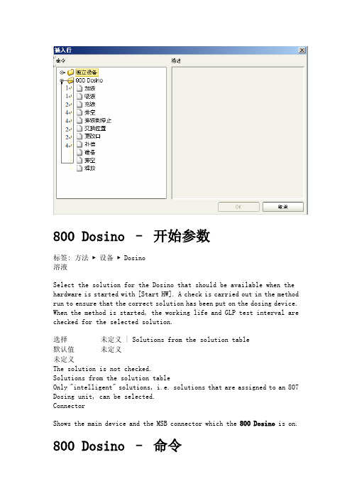
800 Dosino –开始参数标签: 方法▶设备▶ Dosino溶液Select the solution for the Dosino that should be available when the hardware is started with [Start HW]. A check is carried out in the method run to ensure that the correct solution has been put on the dosing device. When the method is started, the working life and GLP test interval are checked for the selected solution.选择未定义 | Solutions from the solution table默认值未定义未定义The solution is not checked.Solutions from the solution tableOnly "intelligent" solutions, i.e. solutions that are assigned to an 807 Dosing unit, can be selected.ConnectorShows the main device and the MSB connector which the 800 Dosino is on.800 Dosino –命令Overview of the time program commands available for the 800 Dosino: 加液对话窗口:方法▶时间程序▶编辑▶‘设备’–加液The device-dependent time program command Dosing (command with feedback) doses the specified volume via the defined port. There is no automatic filling beforehand or afterwards.参数PortPort via which dosing takes place. Formula input possible.1 (4)范围默认值 1V olumeVolume to be transported. Formula input possible.范围0.0000 ... 99999.9000 mL默认值 1.0000 mLDosing rateSpeed at which discharge takes place. The 最大值 rate depends on the cylinder volume of the buret used. Formula input possible.Cylinder volume 2 mL范围0.01 ... 6.00 mL/min默认值 1.00 mL/min选择最大值Filling rateSpeed at which filling takes place. The 最大值 rate depends on the cylinder volume of the buret used. Formula input possible.Cylinder volume 2 mL范围0.01 ... 6.00 mL/min默认值 1.00 mL/min选择最大值命令时间程序命令的可选注释。
EE08 高精度迷你湿度和温度探头用户手册说明书

User ManualEE08High-Precision Miniature Humidity and Temperature ProbeBA_EE08 // v1.4 // Modification rights reservedE+E Elektronik Ges.m.b.H. does not accept warranty and liability claims neither upon this publication nor in case of improper treatment of the described products.The document may contain technical inaccuracies and typographical errors. The content will be revised on a regular basis. These changes will be implemented in later versions. The described products can be improved and changed at any time without prior notice.© Copyright E+E Elektronik® Ges.m.b.H.All rights reserved.USAFCC notice:This device has been tested and found to comply with the conditions for a category B device according to part 15 of the FCC rules and regulations. These conditions were designed to provide adequate protection against EMI in a residential environment. This device generates, uses and can radiate high-frequency energy. If it is not installed and used in accordance with the operating instructions, it may cause electromagnetic interference to radio communications. However there is no guarantee that electromagnetic interference will not occur in a particular installation. If the device does cause electromagnetic interference to radio or television reception (this can be determined by turning the device off and on), the user is advised to remedy the interference with the following measures:• Reorient or relocate the receiving antenna.• Increase the distance between the device and receiver.• Connect the device to a different circuit to that of the receiver.• Consult the dealer or an experienced radio/TV technician.Caution:Any changes to the device not expressly approved by an EMI representative could void the user‘s authority to operate this device.CANADAICES-003 notification:This category B device complies with Canadian standard ICES-003.INHALT1 General (4)1.1 Explanation of Symbols (4)1.2 Safety instructions (4)1.2.1 General Safety Instructions (4)1.2.2 Intended Use (4)1.2.3 Mounting, Start-up and Operation (5)1.3 Environmental Aspects (5)2 Scope of Supply (5)3 Product Description (5)3.1 General (5)3.2 Dimensions (6)3.3 Electrical Connection (6)4 Installation (7)5 Maintenance (7)6 Calibration / Adjustment (7)7 Accessories / Spare Parts (8)8 Technical Data (8)1 GeneralThis user manual serves for ensuring proper handling and optimal functioning of the device. The user manual shall be read before commissioning the equipment and it shall be provided to all staff involved in transport, installation, operation, maintenance and repair. The user manual may not be used for the purposes of competition without the written consent of E+E Elektronik® and may not be forwarded to third parties. Copies may be made for internal purposes. All information, technical data and diagrams included in these instructions are based on the information available at the time of writing.DisclaimerThe manufacturer or his authorized agent can be only be held liable in case of willful or grossnegligence. In any case, the scope of liability is limited to the corresponding amount of the order issued to the manufacturer. The manufacturer assumes no liability for damages incurred due to failure tocomply with the applicable regulations, operating instructions or the specified operating conditions.Consequential damages are excluded from the liability.1.1Explanation of SymbolsThis symbol indicates safety information.It is essential that all safety information is strictly observed. Failure to comply with this information canlead to personal injuries or damage to property. E+E Elektronik® assumes no liability if this happens.This symbol indicates instructions.The instructions shall be observed in order to reach optimal performance of the device.1.2 Safety instructions1.2.1 General Safety InstructionsThe device and mainly the filter cap shall not be exposed to unnecessary mechanical stress.When replacing the filter cap make sure not to touch the sensing elements.The device must be operated with the filter cap on at all times.For sensor cleaning please see “Cleaning Instructions” at /ee08.Installation, electrical connection, maintenance and commissioning shall be performed by qualifiedpersonnel only.Use the EE08 only as intended and observe all technical specifications.Do not use EE08 in explosive atmosphere or for measurement of aggressive gases.This device is not appropriate for safety, emergency stop or other critical applications where devicemalfunction or failure could cause injury to human beings.1.2.2 Intended UseThe EE08 is intended for the humidity (RH) and temperature (T) measurement in applications thatrequire accurate measurement over wide RH and T ranges. It must not be applied in hazardousenvironment with agressive or flammable gases or in explosive areas. For use outdoors and/or inmeteorolgy, optional radiation shields are available. Please refer to chapter 3 Product Description.The use of the EE08 in any other way than described in this manual bears a safety risk for people and the entire measurement installation and is therefore not allowed.The manufacturer cannot be held responsible for damages as a result of incorrect handling, installation, and maintenance of the equipment.In order to avoid damage to the instrument or health hazards, the measuring equipment must never be manipulated with tools that are not specifically described in this manual.The sensor may only be utilized in accordance with the conditions defined in the technical data.Otherwise, measurement inaccuracies will occur and equipment failures cannot be ruled out.The steps recommended by the manufacturer for installation, inspections and maintenance work must be observed and carried out for the safety of the user and for the functionality of the equipment.4User Manual for EE08 Humidity / Temperature ProbeUnauthorized product modification leads to loss of all warranty claims. This may be accomplished only with an explicit permission of E+E Elektronik®!1.2.3 Mounting, Start-up and OperationThe EE08 humidity and temperature probe has been produced under state of the art manufacturingconditions, has been thoroughly tested and has left the factory after fulfilling all safety criteria. Themanufacturer has taken all precautions to ensure safe operation of the device. The user must ensure that the device is set up and installed in a manner that does not have a negative effect on its safeuse. The user is responsible for observing all applicable safety guidelines, local and international, with respect to safe installation and operation on the device. This user manual contains information andwarnings that must be observed by the user in order to ensure safe operation.Mounting, start-up, operation and maintenance of the device may be performed by qualified staffonly. Such staff must be authorized by the operator of the facility to carry out the mentioned activities.The qualified staff must have read and understood this user manual and must follow the instructionscontained within.All process and electrical connections shall be thoroughly checked by authorized staff before puttingthe device into operation.Do not install or start-up a device supposed to be faulty. Make sure that such devices are notaccidentally used by marking them clearly as faulty.A faulty device may only be investigated and possibly repaired by qualified, trained and authorizedstaff. If the fault cannot be fixed, the device shall be removed from the process.Service operations other than described in this user manual may only be performed by themanufacturer.1.3Environmental AspectsProducts from E+E Elektronik® are developed and manufactured observing of all relevant requirements with respect to environment protection. Please observe local regulations for the devicedisposal.For disposal, the individual components of the device must be separated according to local recycling regulations. The electronics shall be disposed of correctly as electronics waste.2 Scope of SupplyEE08 probe according to ordering guideInspection certificate according to DIN EN10204-3.3 Product Description3.1 GeneralThe EE08 is a probe for the highly accurate measurement of humidity (RH) and temperature (T) over wide RH and T ranges of 0...100 % RH and -40...80 °C (-40...176 °F).Typical application fields of the probe areMeteorology / weather stationsHumidity / temperature data loggingIncubatorsFermentation chambersGreen housesSnow machinesDry storage facilitiesThere are two types of probe, the EE08 with cable (type E8) up to 5 m (16.4 ft) length and the EE08 with connector (type E11). For the latter, connection cables with length 1.5 / 3 / 5 / 10 m (5 / 10 / 16.4 / 32.8 ft) are available as accessory.5User Manual for EE08 Humidity / Temperature Probe6User Manual for EE08 Humidity / Temperature ProbeFor outdoor operation the use of an appropriate radiation shield is of paramount importance. The EE08 is compatible with rotational symmetric radiation shields which protect it against rain, snow and overheating caused by direct sunlight (available as accessory HA010502, suitable for type E8 and HA010506, suitable for type E11).3.2 DimensionsFig. 1 Dimensions of EE08 in mm (inch)Fig. 2 Dimensions of optional radiation shields HA010502 and HA010506 in mm (inch)3.3 Electrical ConnectionThe manufacturer cannot be held responsible for personal injuries or damage to property as a result of incorrect handling, installation, wiring, power supply and maintenance of the device.Ground connection:A low impedance connection between the shield of the connection cable and the ground potential isimportant for the flawless operation of the EE08.E2 Voltage Level:Please observe an E2 voltage level of 3.3 V / ±0.1 V on the data lines.4 InstallationThe follwing mounting types are possible:Wall mount with the help of a mounting clip, available as accessory HA010211.Outdoor operation with radiation shield: wall mount or pole mount. Please mind the mountinginstructions included in the manuals of HA010502 and HA010506.5 MaintenanceThe use in dirty, dusty, polluted environment might arise the need for cleaning the sensing head andreplacing the filter cap. In such a case please see the Cleaning Instructions at /ee08.Do not touch the humidity sensor!6 Calibration / AdjustmentDefinitionsCalibration documents the accuracy of a measurement device. The device under test (specimen) iscompared with the reference and the deviations are documented in a calibration certificate. Duringthe calibration, the specimen is not changed or improved in any way.Adjustment improves the measurement accuracy of a device. The specimen is compared with thereference and brought in line with it. An adjustment can be followed by a calibration which documents the accuracy of the adjusted specimen.To carry out a one point or a two point calibration / adjustment, the E2 / RS232 converter (available as an accessory, order code HA011005) and the EE-PCS Product Configuration Software are necessary.The EE-PCS is freely available at /ee08.7User Manual for EE08 Humidity / Temperature Probe7 Accessories / Spare PartsM12 connection cable for type E11, length 1.5 m (5 ft)HA010322M12 connection cable for type E11, length 3 m (10 ft)HA010323M12 connection cable for type E11, length 5 m (16.4 ft)HA010324M12 connection cable for type E11, length 10 m (32.8 ft)HA010325Radiation shield for Type E8HA010502Radiation shield for Type E11HA010506Wall mounting clip Ø12 mm HA010211Protection cap for Ø12 mm probe HA010783M12 female socket with wires HA010703M12 female cable connector assembly possible HA010704Metal grid filter HA010113Cconfiguration cable HA011005EE-PCS free download at /ee088 Technical DataMeasurandsRelative HumidityMeasuring range 0...100 % RHAccuracy at 23 °C (73 °F)for RH ≤ 90 % ±2 % RHand nominal voltage1)f or RH > 90 % ±3 % RHTemperature dependence, typ. 0.03 % RH/°C (0.02 % RH/°F)TemperatureMeasuring range -40...80 °C (-40...176 °F)OutputsAnalogue 0 - 1 V / 0 - 2.5 V / 0 - 5 V / 0 - 10 V -0.2mA < I L < 0.2 mADigital interface E2 interface2)GeneralSupply voltage f or output 0 - 1 V / 0 - 2.5 V V1: 4.5 - 15 V DC V2: 7 - 30 V DCoutput 0 - 5 V V2: 7 - 30 V DCforoutput 0 - 10 V V2: 12 - 30 V DCforCurrent consumption, typ. < 1.3 mAElectrical connection M12x1, 8 polesCable PVC 8 x 0.14 mm² (M1 models)Cable PVC 10 x 0.14 mm² (M6 models)Filter Metal gridProtection rating IP65Enclosure material PolycarbonateElectromagnetic compatibility EN 61326-1 EN 61326-2-3Industrial EnvironmentFCC Part15 Class B ICES-003 Class BOperating and storage conditions -40...80 °C (-40...176 °F)0...100 % RH (operation)0...95 % RH, non-condensing (storage)Adjustment With EE-PCS (Product Configuration Software, free download)and configuration adapter1) The accuracy statement includes the uncertainty of the factory calibration with an enhancement factor k=2 (2-times standard deviation). The accuracy was calculated inaccordance with EA-4/02 and with regard to GUM (Guide to the Expression of Uncertainty in Measurement);nominal voltage V1 = 12 V DC, V2 = 24 V DC2) E2 Voltage Level = 3.3 V / ±0.1 V, for further support literature refer to /ee08.8User Manual for EE08 Humidity / Temperature ProbeHEADQUARTERSE+E Elektronik Ges.m.b.H. Langwiesen 74209 Engerwitzdorf AustriaTel.: +43 7235 605-0E-mail:*************** Web: SUBSIDIARIESE+E Elektronik China18F, Kaidi Financial Building,No.1088 XiangYin Road200433 ShanghaiTel.: +86 21 6117 6129E-mail:**************E+E Elektronik France47 Avenue de l‘Europe92310 SèvresTel.: +33 4 74 72 35 82E-mail:**************E+E Elektronik GermanyObere Zeil 261440 OberurselTel.: +49 6171 69411-0E-mail:**************E+E Elektronik India801, Sakhi Vihar Road400072 MumbaiTel.: +91 990 440 5400E-mail:******************E+E Elektronik ItalyVia Alghero 17/1920128 Milano (MI)Tel.: +39 02 2707 86 36E-mail:**************E+E Elektronik KoreaSuite 2001, Heungdeok ITValley Towerdong, 13,Heungdeok 1-ro, Giheung-gu16954 Yongin-si, Gyeonggi-doTel.: +82 31 732 6050E-mail:**************.krE+E Elektronik USA333 East State ParkwaySchaumburg, IL 60173Tel.: +1 847 490 0520E-mail:*****************。
Thermo Scientific Heraeus Megafuge 8和8R小型实验室离心机产品介

Thermo ScientificHeraeus Megafuge 8 Centrifuge SeriesFits in.Stands out.Introducing the NEW!Thermo Scientific™Heraeus™ Megafuge™ 8 and 8R small benchtop centrifugesFits in.4t o your space, with its compact footprint.Auto-Lock ™ Rotor ExchangeSecure push-button application versatility and cleaning convenienceClickSeal ™ Biocontainment LidsOne-handed, certified 1 sample protectionMaximized Swing-Out CapacityStands out.4d esigned for solid reliability and consistent results.14Ventilated (left) and refrigerated (right)n B iocontainment sealing options, including certified ClickSeal lids for glove-friendly, one-handed operation n M anufactured with quality materials providing broad Simple solutions.Flexible processing.Reliable quality. Safe operation.1B Public Health England, Porton Down, UK Fits in. Stands out.Secure, push-button Auto-Lock rotor exchange in as little as 3 seconds delivers:n Trouble-free rotor installation and removal linical processing up to 24 x 5/7 mL blood tubes per runAccommodates up to 30 spin columns, such as DNA and RNA mini-preps, Micro-volume Solution RotorsSample-ready.User-friendly.n O ne-touch operation with pre-saved protocolsn H ighly visible backlit display for easy reading of parameters across the labn O ptional indicators at end of run, including automatic lid opening, full flashing display andadjustable audible signaln Glove- and detergent-friendlyn M ultilingual instructions – English, Dutch, French, German, Italian, Russian and Spanish — onprogramming, run conditions, alerts andservice messagesExpanded Programming Optionsn A lphanumeric program naming ,of up to 12 characters, promotes correct program selection every time.n P rogram-only mode limits thecontrol of the centrifuge to the set program and the control quadrant (Start, Stop, Pulse and Open), ideal for controlled environmentsFits in. CLINICAL APPLICATIONS.Outstanding capacity in a compact design with a smart, simple interface.n R uns up to 24 x 5/7 mL blood tubes at a time in swinging bucket configuration n A uto-Lock rotor exchange simplifies cleaning n C onforms to the latest clinical and safety standards n F ast acceleration and deceleration times for quicker spinsStands out.TX-150 Swinging Bucket RotorM10 Swinging Bucket Rotor8 x 50 mL Individually Sealed Fixed Angle RotorCLINIConic Fixed Angle RotorHematocrit Rotor1B iocontainment certification by the Public Health England, Porton Down, UKDedicated Rotors for Routine Clinical ProcessingTX-100S Clinical Swinging Bucket Rotor with Sealed Carriers TX-100 Clinical Swinging Bucket Rotor with CarriersInnovative design supports multiple users and applications to stay one step ahead of your evolving research needs.n 8 x 50 mL swinging bucket rotor capacity, 4 microplates, or 30 filtration columns for research needs n A uto-Lock rotor exchange for application flexibility – go from 50 mL tube to microplates to microtubes effortlesslyFits in. RESEARCH APPLICATIONS.Stands out.to 30,279 x g enables • quicker spins• improved separations• access to a wider range of applications while maintaining full swing-out rotor fl exibility, combined with quick, safe Auto-Lock rotor exchange.TX-150 Swinging Bucket RotorM10 Swinging Bucket RotorMT-12 Swinging Bucket RotorHIGHConic III Fixed Angle RotorCLINIConic Fixed Angle RotorMicroClick 18 x 5 RotorMicro-Volume Solution RotorsMicroClick 24 x 2Fixed Angle Rotor8 x 8 PCR Strip FixedAngle Rotor1B iocontainment certification by the Public Health England, Porton Down, UKTX-150 Swinging M10 SwingingBucket Rotor MT-12 Swinging Bucket Rotor23468Versatile Swinging Bucket RotorsMax Tube Max Speed Max RCFTX-100S Clinical Swinging Bucket Rotor TX-100 Clinical Swinging Bucket RotorClinical Swinging Bucket RotorsCat. No. DescriptionRotorCapacity(places xvolume, mL)Max TubeDimensions(O x L, mm)Max Speed(rpm)Max RCF(x g)Max Speed(rpm)Max RCF(x g)Clinical Swinging Bucket Rotors VENTILATED REFRIGERATED75005704TX-100S Clinical Swinging Bucket Rotorwith Sealed Carriers, 90°, R max 144 mm8 x 1517 x 1064,5003,2604,500 3,26075005705TX-100 Clinical Swinging Bucket Rotorwith Carriers, 90°, R max 144 mm16 x 1517 x 1214,5003,2604,5003,260Adapters for TX-100S Clinical Rotor and TX-100 Clinical Rotor (each)1120366613.5 mL Urine Tube16/8 x 13.516 x 82HIGHConic III Rotor8 x 50 mL Rotor MicroClick 18 x 5 Rotor8 x 8 PCR Strip RotorMicroClick 24 x 2 RotorMicroClick 30 x 2 RotorCat. No. Description Rotor Capacity(places xvolume, mL)Max TubeDimensions(O x L, mm)Max Speed(rpm)Hematocrit RotorThermo Scientific Heraeus Megafuge 8 Centrifuge SeriesSpecificationsSwing Bucket RotorsFixed Angle RotorsControl SystemDrive SystemRotor Locking SystemImbalance Detection SystemProgramsPulse (Short) RunAcceleration /Deceleration RatesCentrifugation ChamberMax Timer RangeTemperature RangePre-Cooling FunctionRefrigeration SystemSound LevelOther Features1 Biocontainment certification by the Public Health England, Porton Down, UKFits in. Stands out.Fits in.More centrifuge solutions for your labPerfect Fit. It’s simple. From 1 Liter bottles, to 15 and50 mL conical tubes and microplates, the versatile selection ofThermo Scientific™ Nalgene™ and Nunc™ centrifugationproducts work seamlessly with your complete centrifuge androtor system, bringing together outstanding quality and performance.Thermo Scientific Heraeus Benchtop CentrifugesAccelerate your research with high speeds, rotor versatility and outstanding safety. Fromintuitive controls, to the certified“click” in place, Thermo Scientific Heraeus benchtop centrifuges deliver the perfect blendof capabilities to support micro-volume protocols, a wide range of high volume swing-outapplications and high speed processing.Thermo ScientificSelect from two available speed options, up to 1721,000 x g for high-end research applications, and our extensive rotor portfolio, including:•1 Biocontainment certification by the Public Health England, Porton Down, UK。
阿尔法拉維 CH 900 模块化旋盤分离器系统商品介绍说明书

•High separation efficiency•No gas flashing inside centrifuge•No air entrainment•Small footprint – easy to install and start up•Gentle treatment of the process liquid•Low power consumption•Complete system handling both process and utilityrequirements•Flexible installation possibilities•Robust and reliable designDesignThe system consists of a 18-size fully hermetic separator, a process valve module with valves and components for routing of product and a service liquid modules for utilities in and out from the separator, as well as control and starter cabinet.All metallic parts in contact with the process liquid are made of stainless steel. Gaskets and seals in contact with the product are made of various materials to fit the process needs.The separation system is prepared for completely automated Cleaning in Place (CIP).Available in following executions:•Solid-liquid separation•Liquid-liquid separation•Liquid-liquid-solid separation Available for installation in safe area, zone 2 and zone 1.Scope of supply•Disc stack separator with process and service liquid units •Main process valves of type ball valve •Instrumentation for pressure monitoring•Manual flow regulating valve•Manual pressure regulator valve•Automatic backpressure valve•Flow indication transmitter of volumetric type•Main motor starter with VFD•Control panel with PLC and HMIOptions•Commissioning (on-site or re-mote assisted)•Service agreement•Solids receiving unit: Consists of a collection device and a pump, to pump away discharged solids (mandatory for zone 1 installation, option for safe area and Zone 2installations)•Factory Acceptance Test•UL or CSA versions available on requestWorking principleThe product enters and leaves the separator via the valve module. The flow rate and the counter pressure in the outlet of the separator are controlled by the process and service liquid module.Discharge of solids from the separator bowl is triggered either by a timer or a manual control. The discharged solids are pumped away by the optional solids receiving unit.The valve module also controls the utility liquids for theseparator’s discharge system and for flushing and CIP as wellas an inert gas system for installation in zone 1.45 61.Control cabinet2.Main motor starter and VFD3.Process and service liquid module4.Product inlet5.Standby/Safety water6.Utilities7.Outlet(s) of product(s)8.Drain for separator 9.Solids receiving unit10.Outlet of discharged solidsTechnical dataMaximum motor power67 kW (89.8 HP)1 Actual capacities depend on operating conditionsOutlet 3” ASME B16.5 FlangeCustomer connection ANSI B16,5Gaskets in system PTFE / Graphite product wetted parts Pipe frameAISI 304Bowl weight1200 kg (2645 lbs) 1200 kg (2645 lbs)Dimensional drawingH22690 mm (8 ft 10 inch)W15135 mm (16 ft 10 inch)W23340 mm (10 ft 11 1/2 inch)This document and its contents are subject to copyrights and other intellectual property rights owned by Alfa Laval Corporate AB. No part of this document may be copied, re-produced or transmitted in any form or by any means, or for any purpose, without Alfa Laval Corporate AB’s prior express written permission. Information and services provided in this document are made as a benefit and service to the user, and no representations or warranties are made about the accuracy or suitability of this information and these services for any purpose. All rights are reserved.200000598-2-EN-GB© Alfa Laval Corporate AB How to contact Alfa LavalUp-to-date Alfa Laval contact details for all countries are always availableon our website at 。
- 1、下载文档前请自行甄别文档内容的完整性,平台不提供额外的编辑、内容补充、找答案等附加服务。
- 2、"仅部分预览"的文档,不可在线预览部分如存在完整性等问题,可反馈申请退款(可完整预览的文档不适用该条件!)。
- 3、如文档侵犯您的权益,请联系客服反馈,我们会尽快为您处理(人工客服工作时间:9:00-18:30)。
CHAPTER 9Mechanics of Options MarketsPractice QuestionsProblem 9.1.An investor buys a European put on a share for $3. The stock price is $42 and the strike price is $40. Under what circumstances does the investor make a profit? Under what circumstances will the option be exercised? Draw a diagram showing the variation of the investor’s profit with the stock price at the maturity of the option.The investor makes a profit if the price of the stock on the expiration date is less than $37. In these circumstances the gain from exercising the option is greater than $3. The option will be exercised if the stock price is less than $40 at the maturity of the option. The variation of the investor’s profit with the stock price in Figure S9.1.Figure S9.1 Investor’s profit in Problem 9.1Problem 9.2.An investor sells a European call on a share for $4. The stock price is $47 and the strike price is $50. Under what circumstances does the investor make a profit? Under what circumstances will the option be exercised? Draw a diagram showing the variation of the investor’s profit with the stock price at the maturity of the option.The investor makes a profit if the price of the stock is below $54 on the expiration date. If the stock price is below $50, the option will not be exercised, and the investor makes a profit of $4. If the stock price is between $50 and $54, the option is exercised and the investor makes a profit between $0 and $4. The variation of the investor’s profit with the stock price is asshown in Figure S9.2.Figure S9.2 Investor’s profit in Problem 9.2Problem 9.3.An investor sells a European call option with strike price of K and maturity T and buys a put with the same strike price and maturity. Describe the investor’s position.The payoff to the investor ismax (0)max (0)T T S K K S −−,+−,This is T K S − in all circumstances. The investor’s position is the same as a short position ina forward contract with delivery price K .Problem 9.4.Explain why margins are required when clients write options but not when they buy options.When an investor buys an option, cash must be paid up front. There is no possibility of future liabilities and therefore no need for a margin account. When an investor sells an option, there are potential future liabilities. To protect against the risk of a default, margins are required.Problem 9.5.A stock option is on a February, May, August, and November cycle. What options trade on (a) April 1 and (b) May 30?On April 1 options trade with expiration months of April, May, August, and November. On May 30 options trade with expiration months of June, July, August, and November.Problem 9.6.A company declares a 2-for-1 stock split. Explain how the terms change for a call option with a strike price of $60.The strike price is reduced to $30, and the option gives the holder the right to purchase twice as many shares.Problem 9.7.“Employee stock options issued by a company are different from regular exchange-traded call options on the company’s stock because they can affect the capital structure of the company.” Explain this statement.The exercise of employee stock options usually leads to new shares being issued by the company and sold to the employee. This changes the amount of equity in the capital structure. When a regular exchange-traded option is exercised no new shares are issued and the company’s capital structure is not affected.Problem 9.8.A corporate treasurer is designing a hedging program involving foreign currency options. What are the pros and cons of using (a) the NASDAQ OMX and (b) the over-the-counter market for trading?The NASDAQ OMX offers options with standard strike prices and times to maturity. Options in the over-the-counter market have the advantage that they can be tailored to meet the precise needs of the treasurer. Their disadvantage is that they expose the treasurer to some credit risk. Exchanges organize their trading so that there is virtually no credit risk. Problem 9.9.Suppose that a European call option to buy a share for $100.00 costs $5.00 and is held until maturity. Under what circumstances will the holder of the option make a profit? Under what circumstances will the option be exercised? Draw a diagram illustrating how the profit from a long position in the option depends on the stock price at maturity of the option.Ignoring the time value of money, the holder of the option will make a profit if the stock price at maturity of the option is greater than $105. This is because the payoff to the holder of the option is, in these circumstances, greater than the $5 paid for the option. The option will be exercised if the stock price at maturity is greater than $100. Note that if the stock price is between $100 and $105 the option is exercised, but the holder of the option takes a loss overall. The profit from a long position is as shown in Figure S9.3.Figure S9.3 Profit from long position in Problem 9.9Problem 9.10.Suppose that a European put option to sell a share for $60 costs $8 and is held until maturity. Under what circumstances will the seller of the option (the party with the short position) make a profit? Under what circumstances will the option be exercised? Draw a diagram illustrating how the profit from a short position in the option depends on the stock price at maturity of the option.Ignoring the time value of money, the seller of the option will make a profit if the stock price at maturity is greater than $52.00. This is because the cost to the seller of the option is in these circumstances less than the price received for the option. The option will be exercised if the stock price at maturity is less than $60.00. Note that if the stock price is between $52.00 and $60.00 the seller of the option makes a profit even though the option is exercised. The profit from the short position is as shown in Figure S9.4.Figure S9.4 Profit from short position in Problem 9.10Problem 9.11.Describe the terminal value of the following portfolio: a newly entered-into long forward contract on an asset and a long position in a European put option on the asset with the same maturity as the forward contract and a strike price that is equal to the forward price of the asset at the time the portfolio is set up. Show that the European put option has the same value as a European call option with the same strike price and maturity.The terminal value of the long forward contract is:0T S F −where T S is the price of the asset at maturity and 0F is the forward price of the asset at thetime the portfolio is set up. (The delivery price in the forward contract is also 0F .)The terminal value of the put option is:0max (0)T F S −,The terminal value of the portfolio is therefore00max (0)T T S F F S −+−,0max (0]T S F =,−This is the same as the terminal value of a European call option with the same maturity as the forward contract and an exercise price equal to 0F . This result is illustrated in the FigureS9.5.Figure S9.5 Profit from portfolio in Problem 9.11We have shown that the forward contract plus the put is worth the same as a call with the same strike price and time to maturity as the put. The forward contract is worth zero at the time the portfolio is set up. It follows that the put is worth the same as the call at the time the portfolio is set up.Problem 9.12.A trader buys a call option with a strike price of $45 and a put option with a strike price of $40. Both options have the same maturity. The call costs $3 and the put costs $4. Draw a diagram showing the variation of the trader’s profit with the asset price.Figure S9.6 shows the variation of the trader’s position with the asset price. We can divide the alternative asset prices into three ranges:a) When the asset price less than $40, the put option provides a payoff of 40T S − and thecall option provides no payoff. The options cost $7 and so the total profit is 33T S −.b) When the asset price is between $40 and $45, neither option provides a payoff. There is a net loss of $7.c) When the asset price greater than $45, the call option provides a payoff of 45T S − and the put option provides no payoff. Taking into account the $7 cost of the options, the total profit is 52T S −.The trader makes a profit (ignoring the time value of money) if the stock price is less than $33 or greater than $52. This type of trading strategy is known as a strangle and is discussed in Chapter 11.Figure S9.6 Profit from trading strategy in Problem 9.12Problem 9.13.Explain why an American option is always worth at least as much as a European option on the same asset with the same strike price and exercise date.The holder of an American option has all the same rights as the holder of a European option and more. It must therefore be worth at least as much. If it were not, an arbitrageur could short the European option and take a long position in the American option.Problem 9.14.Explain why an American option is always worth at least as much as its intrinsic value.The holder of an American option has the right to exercise it immediately. The Americanoption must therefore be worth at least as much as its intrinsic value. If it were not anarbitrageur could lock in a sure profit by buying the option and exercising it immediately.Problem 9.15.Explain carefully the difference between writing a put option and buying a call option.Writing a put gives a payoff of min(0)T S K −,. Buying a call gives a payoff ofmax(0)T S K −,. In both cases the potential payoff is T S K −. The difference is that for a written put the counterparty chooses whether you get the payoff (and will allow you to get it only when it is negative to you). For a long call you decide whether you get the payoff (and you choose to get it when it is positive to you.)Problem 9.16.The treasurer of a corporation is trying to choose between options and forward contracts to hedge the corporation’s foreign exchange risk. Discuss the advantages and disadvantages of each.Forward contracts lock in the exchange rate that will apply to a particular transaction in the future. Options provide insurance that the exchange rate will not be worse than some level. The advantage of a forward contract is that uncertainty is eliminated as far as possible. The disadvantage is that the outcome with hedging can be significantly worse than the outcome with no hedging. This disadvantage is not as marked with options. However, unlike forward contracts, options involve an up-front cost.Problem 9.17.Consider an exchange-traded call option contract to buy 500 shares with a strike price of $40 and maturity in four months. Explain how the terms of the option contract change when there isa) A 10% stock dividendb) A 10% cash dividendc) A 4-for-1 stock splita) The option contract becomes one to buy 50011550×.= shares with an exercise price401.13636=..b) There is no effect. The terms of an options contract are not normally adjusted for cash dividends.c) The option contract becomes one to buy 50042000×=, shares with an exercise price of404$10=.Problem 9.18.“If most of the call options on a stock are in the money, it is likely that the stock price has risen rapidly in the last few months.” Discuss this statement.The exchange has certain rules governing when trading in a new option is initiated. These mean that the option is close-to-the-money when it is first traded. If all call options are in the money it is therefore likely that the stock price has increased since trading in the option began.Problem 9.19.What is the effect of an unexpected cash dividend on (a) a call option price and (b) a put option price?An unexpected cash dividend would reduce the stock price on the ex-dividend date. This stock price reduction would not be anticipated by option holders. As a result there would be a reduction in the value of a call option and an increase the value of a put option. (Note that the terms of an option are adjusted for cash dividends only in exceptional circumstances.) Problem 9.20.Options on General Motors stock are on a March, June, September, and December cycle. What options trade on (a) March 1, (b) June 30, and (c) August 5?a)March, April, June and Septemberb)July, August, September, Decemberc)August, September, December, March.Longer dated options may also trade.Problem 9.21.Explain why the market maker’s bid-offer spread represents a real cost to options investors.A “fair” price for the option can reasonably be assumed to be half way between the bid and the offer price quoted by a market maker. An investor typically buys at the market maker’s offer and sells at the market maker’s bid. Each time he or she does this there is a hidden cost equal to half the bid-offer spread.Problem 9.22.A United States investor writes five naked call option contracts. The option price is $3.50, the strike price is $60.00, and the stock price is $57.00. What is the initial margin requirement? The two calculations are necessary to determine the initial margin. The first gives×.+.×−=,500(3502573)5950The second gives×.+.×=,500(350157)4600The initial margin is the greater of these, or $5,950. Part of this can be provided by the initial amount of 50035$1750×.=, received for the options.Further QuestionsProblem 9.23.The price of a stock is $40. The price of a one-year European put option on the stock with a strike price of $30 is quoted as $7 and the price of a one-year European call option on the stock with a strike price of $50 is quoted as $5. Suppose that an investor buys 100 shares, shorts 100 call options, and buys 100 put options. Draw a diagram illustrating how the investor’s profit or loss varies with the stock price over the next year. How does your answer change if the investor buys 100 shares, shorts 200 call options, and buys 200 put options? Figure S9.7 shows the way in which the investor’s profit varies with the stock price in thefirst case. For stock prices less than $30 there is a loss of $1,200. As the stock price increases from $30 to $50 the profit increases from –$1,200 to $800. Above $50 the profit is $800. Students may express surprise that a call which is $10 out of the money is less expensive than a put which is $10 out of the money. This could be because of dividends or the crashophobia phenomenon discussed in Chapter 19.Figure S9.8 shows the way in which the profit varies with stock price in the second case. In this case the profit pattern has a zigzag shape. The problem illustrates how many different patterns can be obtained by including calls, puts, and the underlying asset in a portfolio.Figure S9.7 Profit in first case considered Problem 9.23Figure S9.8 Profit for the second case considered Problem 9.23Problem 9.24.“If a company does not do better than its competitors but the stock market goes up, executives do very well from their stock options. This makes no sense” Discuss this viewpoint. Can you think of alternatives to the usual executive stock option plan that take the viewpoint into account.Executive stock option plans account for a high percentage of the total remuneration receivedby executives. When the market is rising fast, many corporate executives do very well out of their stock option plans — even when their company does worse than its competitors. Large institutional investors have argued that executive stock options should be structured so that the payoff depends how the company has performed relative to an appropriate industry index. In a regular executive stock option the strike price is the stock price at the time the option is issued. In the type of relative-performance stock option favored by institutional investors, the strike price at time t is 00t S I I where 0S is the company’s stock price at the time the optionis issued, 0I is the value of an equity index for the industry in which the company operates atthe time the option is issued, and t I is the value of the index at time t . If the company’s performance equals the performance of the industry, the options are always at-the-money. If the company outperforms the industry, the options become in the money. If the company underperforms the industry, the options become out of the money. Note that a relative performance stock option can provide a payoff when both the market and the company’s stock price decline.Relative performance stock options clearly provide a better way of rewarding seniormanagement for superior performance. Some companies have argued that, if they introduce relative performance options when their competitors do not, they will lose some of their top management talent.Problem 9.25.Use DerivaGem to calculate the value of an American put option on a nondividend paying stock when the stock price is $30, the strike price is $32, the risk-free rate is 5%, the volatility is 30%, and the time to maturity is 1.5 years. (Choose Binomial American for the “option type” and 50 time steps.)a. What is the option’s intrinsic value?b. What is the option’s time value?c. What would a time value of zero indicate? What is the value of an option with zero time value?d. Using a trial and error approach calculate how low the stock price would have to be for the time value of the option to be zero.DerivaGem shows that the value of the option is 4.57. The option’s intrinsic value is 3230200−=.. The option’s time value is therefore 457200257.−.=.. A time value of zero would indicate that it is optimal to exercise the option immediately. In this case the value of the option would equal its intrinsic value. When the stock price is 20, DerivaGem gives the value of the option as 12, which is its intrinsic value. When the stock price is 25, DerivaGem gives the value of the options as 7.54, indicating that the time value is still positive (054=.). Keeping the number of time steps equal to 50, trial and error indicates the time value disappears when the stock price is reduced to 21.6 or lower. (With 500 time steps this estimate of how low the stock price must become is reduced to 21.3.)Problem 9.26.On July 20, 2004 Microsoft surprised the market by announcing a $3 dividend. The ex-dividend date was November 17, 2004 and the payment date was December 2, 2004. Its stock price at the time was about $28. It also changed the terms of its employee stock options so that each exercise price was adjusted downward toPre-dividend Exercise Price ClosingPrice 300ClosingPrice$−.× The number of shares covered by each stock option outstanding was adjusted upward toNumber of Shares Pre-dividend ClosingPrice ClosingPrice 300$−.×"Closing Price" means the official NASDAQ closing price of a share of Microsoft common stock on the last trading day before the ex-dividend date.Evaluate this adjustment. Compare it with the system used by exchanges to adjust for extraordinary dividends (see Business Snapshot 9.1).Suppose that the closing stock price is $28 and an employee has 1000 options with a strike price of $24. Microsoft’s adjustment involves changing the strike price to242528214286×=. and changing the number of options to 100028251120×=,. The system used by exchanges would involve keeping the number of options the same and reducing the strike price by $3 to $21.The Microsoft adjustment is more complicated than that used by the exchange because it requires a knowledge of the Microsoft’s stock price immediately before the stock goes ex-dividend. However, arguably it is a better adjustment than the one used by the exchange. Before the adjustment the employee has the right to pay $24,000 for Microsoft stock that is worth $28,000. After the adjustment the employee also has the option to pay $24,000 for Microsoft stock worth $28,000. Under the adjustment rule used by exchanges the employee would have the right to buy stock worth $25,000 for $21,000. If the volatility of Microsoft remains the same this is a less valuable option.One complication here is that Microsoft’s volatility does not remain the same. It can beexpected to go up because some cash (a zero risk asset) has been transferred to shareholders. The employees therefore have the same basic option as before but the volatility of Microsoft can be expected to increase. The employees are slightly better off because the value of an option increases with volatility.。