汽车电动助力转向系统的研究大学毕业论文外文文献翻译及原文
机械类汽车转向系统外文文献及翻译

1 IntroductionThe key task for the automobile industry and its suppliers in future lies in speedily developing and implementing ecologically sound and economically justifiable mobility systems. Light metals such as aluminum and magnesium along with glass and carbon fiber reinforced materials, ceramics and composites have opened up the potential for considerable weight reduction and for "green" vehicle concepts which can be realized economically. Aluminum in particular can provide the impetus for new designs for the next millennium. Decades ago, the use of aluminum in auto construction was seen as an "experiment"; Today it is a vital factor in reducing weight and thus lowering fuel consumption.The average passenger car today contains 60 to 70 kg of aluminum, and current developments point to a doubling of this amount in the next few years. Motor vehicles both now and in future must meet requirements for: greater performance, greater safety, comfort, low pollution. Lightweight construction is not just about reducing weight; it is a question of -striking the right balance between reduced weight and structural efficiency. In vehicle construction this normally means making the best use of the generally very tight space available for individual components so as to allow weight to be minimized while still meeting all stiffness, strength, natural frequency or acoustical requirements. To achieve this, stresses must be distributed throughout the structure as evenly as possible. Modern numerical analysis methods such as FEA allow a very detailed analysis of system behavior, provide cost-efficient support for the complex process of optimization and thus make a huge contribution to advances in lightweight construction. Packaging, safety considerations, reproducibility and price place restrictions on the degree of weight reduction achievable.The broad range of expertise available to Krupp Presta AG allows the company to analyze customer specifications for steering systems and provide appropriate solutions.2 Requirements to be met by steering systemsThe steering is an important part of the feel of a car. The steering system should make driving an enjoyable experience with no unpleasant vibration from the road surface while guaranteeing the required hand- sing. It is also important that high safety requirements be met, both under normal conditions and in crash situations. The key criteria for the steering system are thus as follows:rolling friction, torsional stiffness /strength, Damping, temperature, corrosion, durability / fatigue, weight. Crash kinematics and energy absorption steering column requirements:natural frequency / stiffness, mass, damping, space, strength (crash, misuse), ergonomics, handling, acoustics, crash kinematics and energy absorption. Other basic conditions:interfaces with adjacent components, installation, joining techniques, price.3 Materialsmaterial light weighting can be achieved by using either stronger or lighter material. When stiffness or natural frequency are Important sizing criteria, low density materials with a high modulus of elasticity by quired. Non-exotic materials must be selected which are readily recyclable, low in price and display good durability.Further requirements are set by the manufacturing and joining processes. Steel, aluminum, magnesium and a variety of plastics are the materials of choice for steering systems.Low specific gravity, high corrosion resistance, low fabricating costs, high energy absorption and good recycle ability make aluminum a favored light weighting material. Owing to its high energy content, up to 90% of the aluminum used in auto construction can be recycled (intelligent design / no mixing with other materials). The favorable energy balance of aluminum puts it at a great advantage over many other materials.In environmental terms aluminum scores highly. The large amounts of primary energy required to make raw aluminum are offset over the lifetime of the vehicle. Composites could also become a very attractive proposition on account of their extreme stiffness, low weight and energy absorption capabilities. At present, howler, price is a problem, as are joining and quality assurance.4 Reducing component weightA focused strategy to reduce component weight requires a lightweight approach to design (force distribution, stresses), material (material selection), specifications (modified, realistic specifications)Key factors in lightweight design include [1]: force flows, material properties, ambient conditions ® safety requirements, reliability of joints, manufacture ability. Practical experience has shown that car makers' specifications based on steel need to be revised for lightweighting. Requirements valid for a steel steering shaft, for example, can result in severe oversizing of an aluminum shaft. Reducing component weight requires material compatible designs combined with material- compatible specifications.5 Lightweight componentsAs part of its development program Krupp Presta is replacing conventional steel steering components such as steering rods , shafts or forks with corresponding aluminum components produced by new processes. Weight savings of 20-30% are achievable depending on the basic conditions stipulated by the customer. Aluminum and magnesium die castings are already being used in steering columns , and further opportunities for weight reduction are being investigated. The lightweight steering column (Fig. 1) produced by Krupp Presta for the Audi A6 is a good example. By using magnesium die castings it has been possible to limit the weight of the steering column to just 5kg, a reduction of 15-20% over conventional (steel) designs.6 Steering column designExperience has shown that it is possible to design steering columns for cars more or less on the basis of their natural frequency alone. Additional engineering work may be required to design critical parts which must not break in the case of a crash or misuse (e.g. theft). The main task when engineering a steering column is thus to achieve the highest possible natural frequencies while minimizing weight. Low-stiffness components are being analyzed and refined in an effort to achieve uniform loading of the structure. In solving this task, use is made of numerical methods such as FEA. The structure is divided into finite elements which are characterized by specific deformation assumptions. Using FE analysis it is possible to examine complex structures, analyze sensitivities and links, discuss variations or ways of making improvements and optimize the structure numerically. Topological optimization is carried out for the analysis of low-stress areas and for the basic design of ribs and beads. CAD geometrydata are processed in an FE pre-processor. Correct modeling of the following is essential, individual parts, stiffness, contact faces, kinematics mass. Modeling is followed by computation and evaluation of the data obtained. The deformation energy is a global measure for assessing stresses. Normalizing the element deformation energy by the element mass provides information on the stresses acting on the element relative to its mass. The kinetic energy is regarded as the influence of vibrating masses which have a negative effect on the natural frequency of the steering column. By evaluating stress and strain conditions, highly localized weak points or high-stress areas can be identified.7 ConclusionsExisting technologies must be continuously adapted and improved in line with the requirements of the auto industry. Systematic weight reduction is a major challenge and requires close cooperation between vehicle manufacturers and suppliers. Materials, fabricating and joining technologies must be further refined. One prerequisite for the continuing success of Krupp Presta is the flexibility to react to customer wishes and requirements.Reference[1] Klein, B.:Leichtbau-Konstruktion. Berech- nungsgrundlagen und Gestaltung.Braunschweig: Vieweg, 1997一、简介一、简介 汽车工业及其供应商,在未来的关键任务在于迅速制定和实施无害生态和经济上合理流动系统。
汽车电动助力转向系统设计 毕业论文

汽车电动助力转向系统设计毕业论文本章主要介绍汽车电动助力转向系统设计的背景和意义,以及论文的目的和结构安排。
汽车转向系统是车辆控制的重要组成部分,它直接影响着驾驶员的操控感受和行车安全性。
随着科技的发展,传统的液压助力转向系统逐渐被电动助力转向系统所取代。
电动助力转向系统通过电力传动装置提供操控力,相较于液压助力转向系统具有更高的效率、更好的节能性和可靠性。
本文的目的是设计一种可靠、高效的汽车电动助力转向系统。
在研究的基础上,将重点关注系统的结构设计、控制算法优化、故障诊断等方面。
通过对系统的设计和优化,可以提高汽车的操控性和安全性。
本文结构安排如下:第二章将介绍汽车电动助力转向系统的背景与发展;第三章将详细阐述系统的设计原理与结构;第四章将重点探讨控制算法的优化与实现;第五章将研究系统的故障诊断方法与技术;最后,第六章将总结全文,并提出进一步研究的展望。
通过本文的研究和实践,相信可以为汽车电动助力转向系统的设计与优化提供一定的参考和借鉴,推动汽车技术的发展与进步。
在这一部分,我们将对汽车电动助力转向系统设计相关的文献进行综述。
我们将总结已有的研究成果,以及当前存在的问题。
具体内容}本文详细介绍了汽车电动助力转向系统设计的方法和步骤,涵盖了传感器选择、电机控制、系统优化等方面。
传感器选择在汽车电动助力转向系统设计中,选择合适的传感器是至关重要的。
传感器可以检测车轮的转向角度、转向速度以及转向力等参数,为后续的电机控制提供必要的数据支持。
常见的传感器包括转向角度传感器、转向速度传感器和转向力传感器。
在选择传感器时,需考虑其精度、响应速度和可靠性等因素,并确保其能与电机控制系统良好地配合。
电机控制在汽车电动助力转向系统中,电机控制是实现转向功能的核心部分。
电机控制系统通过接收传感器提供的数据,计算并控制电机的输出力矩,从而实现汽车的转向功能。
电机控制的关键是控制算法的设计和实现。
常见的电机控制方法有PID控制、模糊控制和神经网络控制等。
汽车新能源论文中英文版

new energy automobileIn 1839, Robert Anderson of Scotland to a carriage mounted on the battery and the electric motor, its successful transformation of the world's first a vehicle driven by electricity, which opened the curtain for the development of electric vehicles.Works flow route of electric vehicles: battery - current - power regulator - motor - drivetrain - drive the vehicle, power drive Move and control system is the core of the electric car is different from different points of the internal combustion engine vehicle;From a global point of view, the development of electric vehicles in China and developed countries almost stand on the same starting line,the vehicle has been initially formed products development system supporting the management mechanism and team composition, pure electric vehicles, hybrid vehicles, fuel cell vehicles, like cars have been achieved, key components, the fuel cell engine is the formation of the system, high-power nickel-hydrogen batteries, lithium-ion battery performance has been greatly enhanced, multi-energy control system initially formed.The main purpose of this writing is to deepen their own understanding of electric vehicles, so that more people understand the new energy and electric vehicles, and the majority of their prime comrades of electric vehicles are interested ability, can also be for our country or for The world automobile Energy to contribute their value.Even China's electric car industry has made a lot of progress, but today such a grim situation, before the dual crisis of energy and the environment has not been resolved, still need to continue to work hard, especially shoulder motherland in the future development of the important task of contemporary college students should the burdens of this great mission and responsibility.新能源汽车1839年,苏格兰的罗伯特·安德森给四轮马车装上了电池和电动机,将其成功改造为世界上第一辆靠电力驱动的车辆由此拉开了电动汽车发展的帷幕。
中英文文献翻译-电动助力转向系统

附录A 外文文献Electric Power Steering system1.HistoryIn automobile development course, Steering system experienced four stages of development: from the initial mechanical Steering system (for your DNS setting Steering, abbreviation ) development for Hydraulic Steering system (Hydraulic Power Steering, abbreviation HPS), then again appeared electronically controlled Hydraulic Steering system (Electro Hydraulic Power Steering, abbreviation EHPS) and Electric Power Steering system (Steering, room Power as EPS). Assemble mechanical steering system of car parking and low-speed driving, when the driver's steering control burden too heavy, in order to solve this problem, the American GM in the 1950s took the lead in the car hydraulic steering system. But, hydraulic steering system can't juggle vehicles to speed portability and high speed, so the steering stability Koyo in Japan in 1983, with the company introduced the application of speed sensing function of hydraulic steering system. This new type of steering system can provide speed increased with the decreasing steering, but complicated structure, cost is higher, and cannot overcome hydraulic system itself has many shortcomings, is a cross between a hydraulic steering and electric power steering the transition between the products. In 1988, Japan Suzuki company first in small cars equipped with Cervo Koyo company development on the steering column, power type electric power steering system; In 1990, Japan Honda NSX in sports car company adopted self-developed rack power type electric power steering system, henceforth unveils the electric power steering in cars applications history2.Working principleElectric power steering system are as follows: first, the working principle, torque sensor measured on steering wheel drivers on the manipulation of the moment, the wheel speed sensors detect the vehicle driving speed, then present the two signals to ECU; According to the built-in control strategy: ECU, calculates the ideal target booster torque, into current instructions to motor; Then, the power generated by the torque motor slowdown institutions amplification on steering system in mechanical manipulation of the moment, and the driver together to overcome resistance torque, realize to the vehicle steering.3. Working processElectric power steering system as traditional hydraulic system alternative products has entered into the auto manufacturing. And had predicted instead, EPS not only applicable to small cars, and some for 12V medium vehicle installed electric system.EPS system includes the following components:The torque sensor: detection steering wheel motion and vehicle motion situation;Electronic control units: according to provide the torque sensor the size of the signal computing power;Motor: according to the electronic control units; turn power output value generation Reduction gear: improve motor power, and produce turn it sends to steering mechanism.Other vehicle system control algorithm input information is provided by the car CAN bus (for example steering Angle and bus speed, etc.). Motor drive also need other information, such as motor rotor position and the three-phase motor sensor (current sensor provided). Motor control by four MOSFET, due to micro controller cannot direct drive of large gate capacitance, MOSFET using drive IC form needed the interface, for safety, complete motor control system must implement monitoring, motor control system integration in PCB, usually contains a relay, the relay use, as the main switch under the condition of the fault detection, disconnect motor and electronic control units.Micro control device must control EPS system and have brushless motor. Micro control device according to the torque sensor provide needed the steering wheel torque information, forming a current control loop. In order to improve the security of the system level, the micro control device should have an on-board oscillator, so even in external oscillator malfunction case, also ensure micro control device performance, also should have chip watchdog. Infineon XC886 integration of the company all the important micro control device component, other safety features for through the software to realize, if must implement safety standards IEC61508 industries, you have to finish all kinds of diagnosis and self-inspection task and increase micro control device work load. At present different customers use of torque sensor and rotor position sensor difference is very big. They use different measuring principle, such as decomposing machine, magnetic resonance device, based on the integration of giant magnet or stance sensor.The role of power levels is switch electric current. The power level has two main functions: drive IC control and protection MOSFET, MOSFET itself and to be responsible for switch currents. MOSFET and partition.Micro control device PWM output port provides driver current and voltage is too low, can't directly connected with MOSFET screen realization. Drive IC role is to provide enough current, the grid to charge for MOSFET, so that in the and discharge 20kHz conditions, and ensure the normal realization switch for discretion side provides the high bar source voltage MOSFET, ensure that you get the low conduction resistance. If the high side MOSFET in open state, to source potential close battery level. Want to make MOSFET arrived at nominal conduction resistance, gate to higher than 8V source voltage. MOSFET completely conduction needed the most ideal voltage is required, therefore 10V or above a grid of potential than battery voltage 10V is higher. Charge pump is to ensure that the function to the largest extent reduce MOSFET power (even if low battery voltage conditions) circuit.The other key charge pump design according to different characteristics that can be PWM pattern request, achieve extremely low (low to 1%) and high rate of 390v (high to 100%). Drive IC another important function is testing, avoid damage to short-circuit mosfets, affected MOSFET will be closed, diagnosis submitted to micro control device.附录B 外文文献的中文翻译电动助力转向系统1.发展历史在汽车的发展历程中,转向系统经历了四个发展阶段:从最初的机械式转向系统(Manual Steering,简称MS)发展为液压助力转向系统(Hydraulic Power Steering,简称HPS),然后又出现了电控液压助力转向系统(Electro Hydraulic Power Steering,简称EHPS)和电动助力转向系统(Electric Power Steering,简称EPS)。
汽车电动助力转向系统的研究大学毕业论文外文文献翻译及原文
毕业设计(论文)外文文献翻译文献、资料中文题目:汽车电动助力转向系统的研究文献、资料英文题目:The auto electric power steering system research 文献、资料来源:文献、资料发表(出版)日期:院(部):专业:班级:姓名:学号:指导教师:翻译日期:2017.02.14英文原文The auto electric power steering system researchAlong with automobile electronic technology swift and violent development, the people also day by day enhance to the motor turning handling quality request. The motor turning system hanged, the hydraulic pressure boost from the traditional machinery changes (Hydraulic Power Steering, is called HPS), the electrically controlled hydraulic pressure boost changes (Electronic Hydraulic Power Steering, is called EHPS), develops the electrically operated boost steering system (Electronic Power Steering, is called EPS), finally also will transit to the line controls the steering system (Steer By Wire, will be called SBW).The machinery steering system is refers by pilot's physical strength achievement changes the energy, in which all power transmission all is mechanical, the automobile changes the movement is operates the steering wheel by the pilot, transmits through the diverter and a series of members changes the wheel to realize. The mechanical steering system by changes the control mechanism, the diverter and major part changes the gearing 3 to be composed.Usually may divide into according to the mechanical diverter form: The gear rack type, follows round the world -like, the worm bearing adjuster hoop type, the worm bearing adjuster refers sells the type. Is the gear rack type and follows using the broadest two kinds round the world -like (uses in needing time big steering force).In follows round the world -like in the diverter, the input changes the circle and the output steering arm pivot angle is proportional; In the gear rack type diverter, the input changes the turn and the output rack displacement is proportional. Follows round the world -like the diverter because is the rolling friction form, thus the transmission efficiency is very high, the ease of operation also the service life are long, moreover bearing capacity, therefore widely applies on the truck. The gear rack type diverter with follows round the world -like compares, the most major characteristic is the rigidity is big, the structure compact weight is light, also the cost is low. Because this way passes on easily by the wheel the reacting force to the steering wheel, therefore has to the pavement behavior response keen merit, but simultaneously also easy to have phenomena and so on goon and oscillation, also its load bearing efficiency relative weak, therefore mainly applies on the compact car and the pickup truck, at present the majority of low end passenger vehicle uses is the gear rack type machinery steering system.Along with the vehicles carrying capacity increase as well as the people to the vehicles handling quality request enhancement, the simple mechanical type steering system were already unable to meet the needs, the power steering system arise at the historic moment, it could rotate the steering wheel while the pilot to provide the boost, the power steering system divides into thehydraulic pressure steering system and the electrically operated steering system 2kinds.Hydraulic pressure steering system is at present uses the most widespread steering system.The hydraulic pressure steering system increased the hydraulic system in the mechanical system foundation, including hydraulic pump, V shape band pulley, drill tubing, feed installment, boost installment and control valve. It with the aid of in the motor car engine power actuation hydraulic pump, the air compressor and the generator and so on, by the fluid strength, the physical strength or the electric power increases the pilot to operate the strength which the front wheel changes, enables the pilot to be possible nimbly to operate motor turning facilely, reduced the labor intensity, enhanced the travel security.The hydraulic pressure boost steering system from invented already had about half century history to the present, might say was one kind of more perfect system, because its work reliable, the technology mature still widely is applied until now. It takes the power supply by the hydraulic pump, after oil pipe-line control valves to power hydraulic cylinder feed, through the connecting rod impetus rotation gear movement, may changes the boost through the change cylinder bore and the flowing tubing head pressure size the size, from this achieved changes the boost the function. The traditional hydraulic pressure type power steering system may divide into generally according to the liquid flow form: Ordinary flow type and atmospheric pressure type 2 kind of types, also may divide into according to the control valve form transfers the valve type and the slide-valve type.Along with hydraulic pressure power steering system on automobile daily popularization, the people to operates when the portability and the road feeling request also day by day enhance, however the hydraulic pressure power steering system has many shortcomings actually: ①Because its itself structure had decided it is unable to guarantee vehicles rotates the steering wheel when any operating mode, all has the ideal operation stability, namely is unable simultaneously to guarantee time the low speed changes the portability and the high speed time operation stability;②The automobile changes the characteristic to drive the pilot technical the influence to be serious;③The steering ratio is fixed, causes the motor turning response characteristic along with changes and so on vehicle speed, transverse acceleration to change, the pilot must aim at the motor turning characteristic peak-to-peak value and the phase change ahead of time carries on certain operation compensation, thus controls the automobile according to its wish travel. Like this increased pilot's operation burden, also causes in the motor turning travel not to have the security hidden danger; But hereafter appeared the electrically controlled hydraulic booster system, it increases the velocity generator in the traditional hydraulic pressure power steering system foundation, enables the automobile along with the vehicle speed change automatic control force size, has to a certain extent relaxed the traditional hydraulic pressure steering system existence question.At present our country produces on the commercial vehicle and the passenger vehicle uses mostly is the electrically controlled hydraulic pressure boost steering system, it is quite mature andthe application widespread steering system. Although the electrically controlled hydraulic servo alleviated the traditional hydraulic pressure from certain degree to change between the portability and the road feeling contradiction, however it did not have fundamentally to solve the HPS system existence insufficiency, along with automobile microelectronic technology development, automobile fuel oil energy conservation request as well as global initiative environmental protection, it in aspect and so on arrangement, installment, leak-proof quality, control sensitivity, energy consumption, attrition and noise insufficiencies already more and more obvious, the steering system turned towards the electrically operated boost steering system development.The electrically operated boost steering system is the present motor turning system development direction, its principle of work is: EPS system ECU after comes from the steering wheel torque sensor and the vehicle speed sensor signal carries on analysis processing, controls the electrical machinery to have the suitable boost torque, assists the pilot to complete changes the operation. In the last few years, along with the electronic technology development, reduces EPS the cost to become large scale possibly, Japan sends the car company, Mitsubishi Car company, this field car company, US's Delphi automobile system company, TRW Corporation and Germany's ZF Corporation greatly all one after another develops EPS.Mercedes2Benz Siemens Automotive Two big companies invested 65,000,000 pounds to use in developing EPS, the goal are together load a car to 2002, yearly produce 300 ten thousand sets, became the global EPS manufacturer. So far, the EPS system in the slight passenger vehicle, on the theater box type vehicle obtains the widespread application, and every year by 300 ten thousand speed development.Steering is the term applied to the collection of components, linkages, etc. which allow for a vessel (ship, boat) or vehicle (car) to follow the desired course. An exception is the case of rail transport by which rail tracks combined together with railroad switches provide the steering function.The most conventional steering arrangement is to turn the front wheels using ahand–operated steering wheel which is positioned in front of the driver, via the steering column, which may contain universal joints to allow it to deviate somewhat from a straight line. Other arrangements are sometimes found on different types of vehicles, for example, a tiller orrear–wheel steering. Tracked vehicles such as tanks usually employ differential steering — that is, the tracks are made to move at different speeds or even in opposite directions to bring about a change of course.Many modern cars use rack and pinion steering mechanisms, where the steering wheel turns the pinion gear; the pinion moves the rack, which is a sort of linear gear which meshes with the pinion, from side to side. This motion applies steering torque to the kingpins of the steered wheels via tie rods and a short lever arm called the steering arm.Older designs often use the recirculating ball mechanism, which is still found on trucks and utility vehicles. This is a variation on the older worm and sector design; the steering column turns a large screw (the "worm gear") which meshes with a sector of a gear, causing it to rotate about its axis as the worm gear is turned; an arm attached to the axis of the sector moves the pitman arm, which is connected to the steering linkage and thus steers the wheels. The recirculating ball version of this apparatus reduces the considerable friction by placing large ball bearings between the teeth of the worm and those of the screw; at either end of the apparatus the balls exit from between the two pieces into a channel internal to the box which connects them with the other end of the apparatus, thus they are "recirculated".The rack and pinion design has the advantages of a large degree of feedback and direct steering "feel"; it also does not normally have any backlash, or slack. A disadvantage is that it is not adjustable, so that when it does wear and develop lash, the only cure is replacement.The recirculating ball mechanism has the advantage of a much greater mechanical advantage, so that it was found on larger, heavier vehicles while the rack and pinion was originally limited to smaller and lighter ones; due to the almost universal adoption of power steering, however, this is no longer an important advantage, leading to the increasing use of rack and pinion on newer cars. The recirculating ball design also has a perceptible lash, or "dead spot" on center, where a minute turn of the steering wheel in either direction does not move the steering apparatus; this is easily adjustable via a screw on the end of the steering box to account for wear, but it cannot be entirely eliminated or the mechanism begins to wear very rapidly. This design is still in use in trucks and other large vehicles, where rapidity of steering and direct feel are less important than robustness, maintainability, and mechanical advantage. The much smaller degree of feedback with this design can also sometimes be an advantage; drivers of vehicles with rack and pinion steering can have their thumbs broken when a front wheel hits a bump, causing the steering wheel to kick to one side suddenly (leading to driving instructors telling students to keep their thumbs on the front of the steering wheel, rather than wrapping around the inside of the rim). This effect is even stronger with a heavy vehicle like a truck; recirculating ball steering prevents this degree of feedback, just as it prevents desirable feedback under normal circumstances.The steering linkage connecting the steering box and the wheels usually conforms to a variation of Ackermann steering geometry, to account for the fact that in a turn, the inner wheel is actually traveling a path of smaller radius than the outer wheel, so that the degree of toe suitable for driving in a straight path is not suitable for turns.As vehicles have become heavier and switched to front wheel drive, the effort to turn the steering wheel manually has increased - often to the point where major physical exertion is required. To alleviate this, auto makers have developed power steering systems. There are two types of power steering systems—hydraulic and electric/electronic. There is also ahydraulic-electric hybrid system possible.A hydraulic power steering (HPS) uses hydraulic pressure supplied by an engine-driven pump to assist the motion of turning the steering wheel. Electric power steering (EPS) is more efficient than the hydraulic power steering, since the electric power steering motor only needs to provide assist when the steering wheel is turned, whereas the hydraulic pump must run constantly. In EPS the assist level is easily tunable to the vehicle type, road speed, and even driver preference. An added benefit is the elimination of environmental hazard posed by leakage and disposal of hydraulic power steering fluid.An outgrowth of power steering is speed adjustable steering, where the steering is heavily assisted at low speed and lightly assisted at high speed. The auto makers perceive that motorists might need to make large steering inputs while manoeuvering for parking, but not while traveling at high speed. The first vehicle with this feature was the Citroën SM with its Diravi layout, although rather than altering the amount of assistance as in modern power steering systems, it altered the pressure on a centring cam which made the steering wheel try to "spring" back to the straight-ahead position. Modern speed-adjustable power steering systems reduce the pressure fed to the ram as the speed increases, giving a more direct feel. This feature is gradually becoming commonplace across all new vehicles.Four-wheel steering (or all wheel steering) is a system employed by some vehicles to increase vehicle stability while maneuvering at high speed, or to decrease turning radius at low speed.In most four-wheel steering systems, the rear wheels are steered by a computer and actuators. The rear wheels generally cannot turn as far as the Alternatively, several systems, including Delphi's Quadrasteer and the system in Honda's Prelude line, allow for the rear wheels to be steered in the opposite direction as the front wheels during low speeds. This allows the vehicle to turn in a significantly smaller radius — sometimes critical for large trucks or vehicles with trailers.Electronic power steering systemWhat it isElectrically powered steering uses an electric motor to drive either the power steering hydraulic pump or the steering linkage directly. The power steering function is therefore independent of engine speed, resulting in significant energy savings.How it works :Conventional power steering systems use an engine accessory belt to drive the pump, providing pressurized fluid that operates a piston in the power steering gear or actuator to assist the driver.In electro-hydraulic steering, one electrically powered steering concept uses a high efficiency pump driven by an electric motor. Pump speed is regulated by an electric controller to vary pump pressure and flow, providing steering efforts tailored for different driving situations. The pump can be run at low speed or shut off to provide energy savings during straight ahead driving (which is most of the time in most world markets).Direct electric steering uses an electric motor attached to the steering rack via a gear mechanism (no pump or fluid). A variety of motor types and gear drives is possible. A microprocessor controls steering dynamics and driver effort. Inputs include vehicle speed and steering, wheel torque, angular position and turning rate.Working In Detail:A "steering sensor" is located on the input shaft where it enters the gearbox housing.The steering sensor is actually two sensors in one: a "torque sensor" that converts steering torque input and its direction into voltage signals, and a "rotation sensor" that converts the rotation speed and direction into voltage signals. An "interface" circuit that shares the same housing converts the signals from the torque sensor and rotation sensor into signals the control electronics can process.Inputs from the steering sensor are digested by a microprocessor control unit that also monitors input from the vehicle's speed sensor. The sensor inputs are then compared to determine how much power assist is required according to a preprogrammed "force map" in the control unit's memory. The control unit then sends out the appropriate command to the "power unit" which then supplies the electric motor with current. The motor pushes the rack to the right or left depending on which way the voltage flows (reversing the current reverses the direction the motor spins). Increasing the current to the motor increases the amount of power assist.The system has three operating modes: a "normal" control mode in which left or right power assist is provided in response to input from the steering torque and rotation sensor's inputs; a "return" control mode which is used to assist steering return after completing a turn; and a "damper" control mode that changes with vehicle speed to improve road feel and dampen kickback.If the steering wheel is turned and held in the full-lock position and steering assist reaches a maximum, the control unit reduces current to the electric motor to prevent an overload situation that might damage the motor. The control unit is also designed to protect the motor against voltage surges from a faulty alternator or charging problem.The electronic steering control unit is capable of self-diagnosing faults by monitoring the system's inputs and outputs, and the driving current of the electric motor. If a problem occurs, the control unit turns the system off by actuating a fail-safe relay in the power unit. This eliminates all power assist, causing the system to revert back to manual steering. A dash EPS warning light is also illuminated to alert the driver. To diagnose the problem, a technician jumps the terminals on the service check connector and reads out the trouble codes.Electric power steering systems promise weight reduction, fuel savings and package flexibility, at no cost penalty.Europe's high fuel prices and smaller vehicles make a fertile testbed for electric steering, a technology that promises automakers weight savings and fuel economy gains. And in a short time, electric steering will make it to the U.S., too. "It's just just a matter of time," says Aly Badawy, director of research and development for Delphi Saginaw Steering Systems in Saginaw, Mich. "The issue was cost and that's behind us now. By 2002 here in the U.S. the cost of electric power steering will absolutely be a wash over hydraulic."Today, electric and hybrid-powered vehicles (EV), including Toyota's Prius and GM's EV-1, are the perfect domain for electric steering. But by 2010, a TRW Inc. internal study estimates that one out of every three cars produced in the world will be equipped with some form of electrically-assisted steering. The Cleveland-based supplier claims its new steering systems could improve fuel economy by up to 2 mpg, while enhancing handling. There are true bottom-line benefits as well for automakers by reducing overall costs and decreasing assembly time, since there's no need for pumps, hoses and fluids.Another claimed advantage is shortened development time. For instance, a Delphi group developed E-TUNE, a ride-and-handling software package that can be run off a laptop computer. "They can take that computer and plug it in, attach it to the controller and change all the handling parameters -- effort level, returnability, damping -- on the fly," Badawy says. "It used to take months." Delphi has one OEM customer that should start low-volume production in '99.Electric steering units are normally placed in one of three positions: column-drive, pinion-drive and rack-drive. Which system will become the norm is still unclear. Short term, OEMs will choose the steering system that is easiest to integrate into an existing platform. Obviously, greater potential comes from designing the system into an all-new platform."We have all three designs under consideration," says Dr. Herman Strecker, group vice president of steering systems division at ZF in Schwaebisch Gmuend, Germany. "It's up to the market and OEMs which version finally will be used and manufactured.""The large manufacturers have all grabbed hold of what they consider a core technology," explains James Handysides, TRW vice president, electrically assisted steering in Sterling Heights, Mich. His company offers a portfolio of electric steering systems (hybrid electric, rack-, pinion-, and column-drive). TRW originally concentrated on what it still believes is the purest engineering solution for electric steering--the rack-drive system. The system is sometimes refered to as direct drive or ball/nut drive.Still, this winter TRW hedged its bet, forming a joint venture with LucasVarity. The British supplier received $50 million in exchange for its electric column-drive steering technology and as sets. Initial production of the column and pinion drive electric steering systems is expected to begin in Birmingham, England, in 2000."What we lack is the credibility in the steering market," says Brendan Conner, managing director, TRW/LucasVarity Electric Steering Ltd. "The combination with TRW provides us with a good opportunity for us to bridge that gap." LucasVarity currently has experimental systems on 11 different vehicle types, mostly European. TRW is currently supplying its EAS systems for Ford and Chrysler EVs in North America and for GM's new Opel Astra.In 1995, according to Delphi, traditional hydraulic power steering systems were on 7596 of all vehicles sold globally. That 37-million vehicle pool consumes about 10 million gallons in hydraulic fluid that could be superfluous, if electric steering really takes off.The present invention relates to an electrically powered drive mechamsm for providing powered assistance to a vehicle steering mechanism. According to one aspect of the presentinvention, there is provided an electrically powered driven mechanism for providing powered assistance to a vehicle steering mechanism having a manually rotatable member for operating the steering mechanism, the drive mechanism including a torque sensor operable to sense torque being manually applied to the rotatable member, an electrically powered drive motor drivingly connected to the rotatable member and a controller which is arranged to control the speed and direction of rotation of the drive motor in response to signals received from the torque sensor, the torque sensor including a sensor shaft adapted for connection to the rotatable member to form an extension thereof so that torque is transmitted through said sensor shaft when the rotatable member is manually rotated and a strain gauge mounted on the sensor shaft for producing a signal indicative of the amount of torque being transmitted through said shaft.Preferably the sensor shaft is non-rotatably mounted at one axial end in a first coupling member and is non-rotatably mounted at its opposite axial end in a second coupling member, the first and second coupling members being inter-engaged to permit limited rotation therebetween so that torque under a predetermined limit is transmitted by the sensor shaft only and so that torque above said predetermined limit is transmitted through the first and second coupling members.The first and second coupling members are preferably arranged to act as a bridge for drivingly connecting first and second portions of the rotating member to one another.Preferably the sensor shaft is of generally rectangular cross-section throughout the majority of its length.Preferably the strain gauge includes one or more SAW resonators secured to the sensor shaft.Preferably the motor is drivingly connected to the rotatable member via a clutch.Preferably the motor includes a gear box and is concentrically arranged relative to the rotatable member.Various aspects of the present invention will hereafter be described, with reference to the accompanying drawings, in which :Figure 1 is a diagrammatic view of a vehicle steering mechanism including an electrically powered drive mechanism according to the present invention,Figure 2 is a flow diagram illustrating interaction between various components of the drive mechanism shown in Figure 1 ,Figure 3 is an axial section through the drive mechanism shown in Figure 1, Figure 4 is a sectional view taken along lines IV-IV in Figure 3,Figure 5 is a more detailed exploded view of the input drives coupling shown in Figure 3, andFigure 6 is a more detailed exploded view of the clutch showing in Figure 3. Referring initially to Figure 1 , there is shown a vehicle steering mechanism 10 drivingly connected to a pair of steerable road wheels The steering mechanism 10 shown includes a rack and pinion assembly 14 connected to the road wheels 12 via joints 15. The pinion(not shown) of assembly 14 is rotatably driven by a manually rotatable member in the form of a steering column 18 which is manually rotated by a steering wheel 19.The steering column 18 includes an electric powered drive mechanism 30 which includes an electric drive motor (not shown in Figure 1) for driving the pinion in response to torque loadings in the steering column 18 in order to provide power assistance for the operative when rotating the steering wheel 19.As schematically illustrated in Figure 2, the electric powered drive mechanism includes a torque sensor20 whichmeasures the torque applied by the steering column 18 when driving the pinion and supplies a signal to a controller 40. The controller 40 is connected to a drive motor 50 and controls the electric current supplied to the motor 50 to control the amount of torque generated by the motor 50 and the direction of its rotation.The motor 50 is drivingly connected to the steering column 18 preferably via a gear box 60, preferably an epicyclic gear box, and a clutch 70. The clutch 70 is preferably permanently engaged during normal operation and is operative under certain conditions to isolate drive from the motor 50 to enable the pinion to be driven manually through the drive mechanism 30. This is a safety feature to enable the mechanism to function in the event of the motor 50 attempting to drive the steering column too fast and/or in the wrong direction or in the case where the motor and/or gear box have seized.The torque sensor 20 is preferably an assembly including a short sensor shaft on which is mounted a strain gauge capable of accurately measuring strain in the sensor shaft brought about by the application of torque within a predetermined range.Preferably the predetermined range of torque which is measured is 0-lONm; more preferably is about l-5Nm.Preferably the range of measured torque corresponds to about 0-1000 microstrain and the construction of the sensor shaft is chosen such that a torque of 5Nm will result in a twist of less than 2°in the shaft, more preferably less than 1 ° .Preferably the strain gauge is a SAW resonator, a suitable SAW resonator being described in WO91/13832. Preferably a configuration similar to that shown in Figure 3 of WO91/13832 is utilised wherein twoSAW resonators are arranged at 45° to the shaft axis and at 90°to one another.Preferably the resonators operate with a resonance frequency of between 200-400 MHz and are arranged to produce a signal to the controller 40 of 1 MHz ±500 KHz depending upon the direction of rotation of the sensor shaft. Thus, when the sensor shaft is not being twisted due to the absence of torque, it produces a 1 MHz signal.When the sensor shaft is twisted in one direction it produces a signal between 1.0 to 1.5 MHz. When the sensor shaft is twisted in the opposite direction it produces a signal between 1.0 to 0.5 MHz. Thus the same sensor is able to produce a signal indicative of the degree of torque and also the direction of rotation of the sensor shaft.Preferably the amount of torque generated by the motor in response to a measured torque of between 0-10Nm is 0-40Nm and for a measured torque of between l-5Nm is 0-25Nm.Preferably a feed back circuit is provided whereby the electric current being used by the motor is measured and compared by the controller 40 to ensure that the motor is running in the correct direction and providing the desired amount of power assistance. Preferably the controller acts to reduce the measured torque to zero and so controls the motor to increase its torque output to reduce the measured torque.A vehicle speed sensor (not shown) is preferably provided which sends a signal indicative of vehicle speed to the controller. The controller uses this signal to modify the degree of power assistance provided in response to the measured torque.Thus at low vehicle speeds maximum power assistance will be provided and a high vehicle speeds minimum power assistance will be provided.The controller is preferably a logic sequencer having a field。
汽车转向系统外文原文及翻译
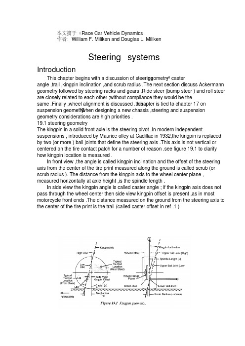
作者:William F. Miliken and Douglas L. MilikenSteering systemsIntroductionThis chapter begins with a discussion of steeringgeometry¡ªcasterangle ,trail ,kingpin inclination ,and scrub radius .The next section discuss Ackermann geometry followed by steering racks and gears .Ride steer (bump steer ) and roll steer are closely related to each other ;without compliance they would be thechapter is tied to chapter 17 onsame .Finally ,wheel alignment is discussed .this¨C when designing a new chassis ,steering and suspension suspension geometrygeometry considerations are high priorities .19.1 steering geometryThe kingpin in a solid front axle is the steering pivot .In modern independent suspensions , introduced by Maurice olley at Cadillac in 1932,the kingpin is replaced by two (or more ) ball joints that define the steering axis .This axis is not vertical or centered on the tire contact patch for a number of reason .see figure 19.1 to clarify how kingpin location is measured .In front view ,the angle is called kingpin inclination and the offset of the steering axis from the center of the tire print measured along the ground is called scrub (or scrub radius ). The distance from the kingpin axis to the wheel center plane , measured horizontally at axle height ,is the spindle length .In side view the kingpin angle is called caster angle ; if the kingpin axis does not pass through the wheel center then side view kingpin offset is present ,as in most motorcycle front ends .The distance measured on the ground from the steering axis to the center of the tire print is the trail (called caster offset in ref .1 )作者:William F. Miliken and Douglas L. MilikenSteering systemsIntroductionThis chapter begins with a discussion of steeringgeometry¡ªcasterangle ,trail ,kingpin inclination ,and scrub radius .The next section discuss Ackermann geometry followed by steering racks and gears .Ride steer (bump steer ) and roll steer are closely related to each other ;without compliance they would be thechapter is tied to chapter 17 onsame .Finally ,wheel alignment is discussed .this¨C when designing a new chassis ,steering and suspension suspension geometrygeometry considerations are high priorities .19.1 steering geometryThe kingpin in a solid front axle is the steering pivot .In modern independent suspensions , introduced by Maurice olley at Cadillac in 1932,the kingpin is replaced by two (or more ) ball joints that define the steering axis .This axis is not vertical or centered on the tire contact patch for a number of reason .see figure 19.1 to clarify how kingpin location is measured .In front view ,the angle is called kingpin inclination and the offset of the steering axis from the center of the tire print measured along the ground is called scrub (or scrub radius ). The distance from the kingpin axis to the wheel center plane , measured horizontally at axle height ,is the spindle length .In side view the kingpin angle is called caster angle ; if the kingpin axis does not pass through the wheel center then side view kingpin offset is present ,as in most motorcycle front ends .The distance measured on the ground from the steering axis to the center of the tire print is the trail (called caster offset in ref .1 )作者:William F. Miliken and Douglas L. MilikenSteering systemsIntroductionThis chapter begins with a discussion of steeringgeometry¡ªcasterangle ,trail ,kingpin inclination ,and scrub radius .The next section discuss Ackermann geometry followed by steering racks and gears .Ride steer (bump steer ) and roll steer are closely related to each other ;without compliance they would be thechapter is tied to chapter 17 onsame .Finally ,wheel alignment is discussed .this¨C when designing a new chassis ,steering and suspension suspension geometrygeometry considerations are high priorities .19.1 steering geometryThe kingpin in a solid front axle is the steering pivot .In modern independent suspensions , introduced by Maurice olley at Cadillac in 1932,the kingpin is replaced by two (or more ) ball joints that define the steering axis .This axis is not vertical or centered on the tire contact patch for a number of reason .see figure 19.1 to clarify how kingpin location is measured .In front view ,the angle is called kingpin inclination and the offset of the steering axis from the center of the tire print measured along the ground is called scrub (or scrub radius ). The distance from the kingpin axis to the wheel center plane , measured horizontally at axle height ,is the spindle length .In side view the kingpin angle is called caster angle ; if the kingpin axis does not pass through the wheel center then side view kingpin offset is present ,as in most motorcycle front ends .The distance measured on the ground from the steering axis to the center of the tire print is the trail (called caster offset in ref .1 )no diagonal weight jacking will occur .3. Caster angle affects steer-camber but ,unlike kingpin inclination ,the effect is favorable . With positive caster angle the outside wheel will camber in a negative direction (top of the wheel toward the center of the car ) while the inside wheel cambers in a positive direction , again learning into the turn .(steer out of the turn ) is used and in this case In skid recovery , ¨Dopposite lock ¡¬the steer¨Ccamber resulting from caster angle is in the ¨Dwrong ¡¬ direction for increased front tire grip . conveniently ,this condition results from very low lateral force at therear so large amounts of front grip are not needed .4. As discussed in chapter 2, tires have pneumatic trail which effectively adds to (and at high slip Angles subtracts from ) the mechanical trail . This tire effect is nonlinear with lateral force and affects steering torque and driver feel .In particular ,the fact that pneumatic trail approaches zero as the tire reaches the limit will result in lowering the self-centering torque and can be s signal to the driver that the tire is near breakaway .The pneumatic trail ¨Dbreakaway signal¡¬ will be swamped out by mechanical trail if the mechanical trail is large compared to the pneumatic trail .5.Sometimes the trail is measured in a direction perpendicular to the steering axis (rather than horizontal as shown in figure 19.1) because this more accurately describes the lever (moment ) arm that connects the tire lateral forces to the kingpin . Tie rod locationNote that in figure 19.1 a shaded area is shown for the steering tie rod location . Camber compliance under lateral force is unavoidable and if the tie rod is located as noted ,the effect on the steering will be in the understeer ( steer out of the turn ) direction becomes much more complex than can be covered here .19.2 Ackerman steering geometryAs the front wheels of a vehicle are steered away from the straight-aheadposition ,the design of the steering linkage will determine if the wheels stay parallel orif one wheel steers more than the other .This difference in steer Angles on the left and right wheels should not be confused with toe-in or toe-out which are adjustments and add to ( or subtract from ) Ackerman geometric effects .For low lateral acceleration usage (street cars) it is common to use Ackerman geometry . as seen on the left of figure 19.2, this geometry ensures that all the wheels roll freely with no slip Angles because the wheels are steered to track a common turn center . Note that at low speed all wheels are on a significantly different radius , the inside front wheel must steer more than the outer front wheel . A reasonable approximation to this geometry may be as shown in figure 19.3.According to ref .99, Rudolf Ackerman patented the double pivot steering systemin 1817 and in 1878, Charles Jeantaud added the concept mentioned above to eliminate wheel scrubbing when cornering . Another reason for Ackermanngeometry ,mentioned by Maurice olley , was to keep carriage wheels from upsetting smooth gravel driveways .High lateral accelerations change the picture considerably . Now the tires alloperate at significant slip Angles and the loads on the inside track are less than on the outside track . Looking back to the tire performance curves ,it is seen that less slip angle is required at lighter loads to reach the peak of the cornering force to a higher slip angle than required for maximum side force . Dragging the inside tire along at high slip Angles ( above for peak lateral force ) raise the tire temperature and slows the car down due to slip angle ( induced ) drag .For racing , it is common to use parallel steering or even reverse Ackermann as shown on the center and right side of figure 19.2.It is possible to calculate the correct amount of reverse Ackermann if the tire properties and loads are known . In most cases the resulting geometry is found to be too extreme because the car must also be driven (or pushed ) at low speeds , for example in the pits .Another point to remember is that most turns in racing have a fairly large radius and the Ackermann effect is very small . In fact , unless the steering system and suspension are very stiff ,compliance (deflection ) under cornering loads may steer the wheels more than any Ackermann (or reverse Ackermann ) built into the geometry .The simplest construction that generates Ackermannn geometry is shown in figure 19.3 for ¨Drear steer ¡¬ . Here ,the rack (cross link or relay rod in steering box systems ) is located behind the front axle and lines staring at the kingpin axis , extended through the outer tie rod ends , intersect in the center of the rear axle . The angularity of the steering knuckle will cause the inner wheel to steer more than the outer (toe-out on turning ) and a good approximation of ¨Dperfect Ackermann ¡¬ will be achieved .The second way to design-in differences between inner and outer steer Angles is by moving the rack (or cross link ) forward or backward so that it is no longer on a line directly connecting the two outer tie rod ball joints .This is shown in figure 19.4. with ¨Drear steer ¡¬ , as shown in the figure ,moving the rack forward will tend more toward parallel steer (and eventually reverse Ackermann ), and moving it toward the rear of the car will increase the toe-out on turning .A third way to generate toe with steering is simply to make the steering arms different lengths . A shorter steering arm (as measured from the kingpin axis to the outer tie rod end ) will be steered through a larger angle than one with a longer knuckle. Of course this effect is asymmetric and applies only to cars turning in one direction¡ªoval track cars .RecommendationWith the conflicting requirements mentioned above , the authors feel that parallel steer or a bit of reverse Ackermann is a reasonable compromise . With parallel steer , the car will be somewhat difficult to push through the pits because the front wheels will be fighting each other . at racing speeds , on large-radius turns , the front wheels are steered very little , thus any ackermann effects will not have a large effect on the individual wheel slip angles , relative to a reference steer angle , measured at the centerline of the car .》 文献翻译 摘自《Race Car Vehicle Dynamics第19章 转向系统 序言: 本章以转向几何参数的讨论为开始,包括主销后倾角,后倾拖距,主销内倾角,主销偏置量。
电动助力转向系统的研究与
电动助力转向系统的研究与洛阳理工学院毕业设计(论文)电动助力转向系统的研究与设计摘要电动助力转向系统(Electric Power Steering System,简称EPS),是汽车工程领域的热门课题之一。
本文在研究了电动助力转向系统工作原理的基础上,设计开发了EPS的电子控制单元ECU (Electronic Control Unit)的硬件电路和相应的控制软件框图。
本文详细分析了电动助力转向系统电子控制单元的功能,研究开发了以89c52单片机为微处理器的电子控制单元。
控制单元具有实时数据信号采集和系统控制功能,根据采集的数据信号,确定电动机输出的目标电流,利用PWM脉宽调制技术,通过H桥式电路控制电动机的输出电流和转动方向,实现助力转向功能。
在研制了实验用ECU装置后,开发了相应的控制软件。
控制软件分为控制策略的实现和数据信号采集与分析两部分。
整个软件系统采用了模块化的设计思想。
在数据信号采集与控制部分,设计了系统主程序、A/D采集程序、车速信号采集程序和PWM控制程序。
本文所设计的EPS电子控制单元性能稳定,结构合理,与整车匹配性能好,可保证EPS实现良好的转向助力效果。
关键词:电动助力转向电子控制单元单片机控制策略Electronic power steering system Research and DesignABSTRACTElectric Power Steering System (EPS) is one of the focuses research in automotive engineering. This paper is based on the principles of EPS to study the operation, designed and developed the Electronic Control Unit (ECU) and the soft ware diagram of the ECU.The thesis Considers the functions of the electronic control unit of EPS, studied and developed the hardware that adopted 89c51as its microprocessor. The control unit was able to realize real-time data/signal acquisition and system control. The target current of motor output could be determined by the obtained data; and utilizing the Pulse-Width Modulation (PWM) technology, power could be provided to the steering system by controlling the output current and rotation direction through H-bridge circuit.The software program, which was divided into the realization of control strategy and the acquisition & control of data/signal, was developed in modular after the design of experimental ECU was completed. And the main program, A/D acquisition program, speed signal acquisition program and PWM control program are developed in the second part.The result showed that the electronic control unit designed was with stable performance, appropriate structure and excellent matching condition, and the excellent power steering effect could be ensured by EPS.Key words: Electric Power Steering System (EPS) Electronic Control Unit Single-Chip Microprocessor Control Strategy目录前言 (1)第1章绪论 (2)1.1汽车电动助力转向系统的特点 (2)1.2电动助力转向系统国内外的研究现状 (4)1.3 EPS的发展趋势和急待解决的核心技术 (5)1.4本课题研究的目的与意义 (6)第2章电动助力转向系统方案确定及工作原理 (7)2.1电动助力转向系统的工作原理 (9)2.1.1电动助力转向系统的组成和工作原理 (9)2.1.2电动助力转向系统的分类 (11)2.1.3电动助力转向系统的技术要求 (12)2.2电动助力转向系统的数学模型 (13)2.2.1转向盘和转向柱输入轴子模型 (14)2.2.2电动机模型 (14)2.2.3输出轴子模型 (16)2.2.4齿轮齿条子模型 (16)2.3电动助力转向系统的主要部分 (17)2.3.1转矩传感器 (18)2.3.2车速传感器 (19)2.3.3直流电动机 (20)2.3.4电磁离合器 (21)2.3.5减速机构 (22)2.3.6电子控制单元ECU (23)第3章电动助力转向系统的硬件设计 (24)3.1电子动力转向系统控制器的总体结构 (24)3.2控制器微处理芯片的选择 (26)3.2.1控制器微处理器常用芯片及选型 (26)3.2.2 89C52芯片及A/D转换芯片介绍 (26)3.2.3 89C52外部总线扩展及片外ROM的连接 (28)3.3控制器输入通道的设计 (30)3.3.1转矩信号的采集 (30)3.3.2电动机电流信号的采集 (31)3.3.3车速信号的采集 (33)3.4控制器输出通道的设计 (34)3.4.1电动机的PWM控制 (34)3.4.2电磁离合器和显示控制电路的设计 (39)3.4.3 电动机保护电路及继电器驱动电路设计 (40)3.5系统供电电源电路设计 (41)3.6系统硬件抗干扰措施 (42)第4章电动助力转向系统的软件设计 (45)4.1 EPS的控制策略 (45)4.1.1 EPS的PID控制 (45)4.2电子动力转向系统各功能模块的软件设计 (48)4.2.1 A/D采集程序 (49)4.2.2 PWM控制程序 (50)4.2.3车速信号采集程序 (51)4.2.4系统主程序 (53)结论 (55)谢辞 (56)参考文献 (57)附录 (59)外文资料翻译 (66)前言转向系统作为汽车的一个重要组成部分,其性能的好坏将直接影响到汽车的转向特性、稳定性和行驶安全性。
转向系统的发展外文文献翻译、中英文翻译、外文翻译
的动态特征时,以低段参数效果不是很好,如果没有,目标车辆液压系统也必须在发动机驱动。
因此,能源消耗,增加燃料发动机,现有的液压油泄漏问题应该不仅污染环境,而且容易影响其他组件。
针对低温,液压系统性能很差。
近年来,随着电子技术的广泛应用,转向系统也越来越多的使用电子设备。
因此,变成使用电子控制系统出现相应的电动液压助力转向系统。
电动液压动力转向系统可以分为两类:电动液压操舵系统(电液压动力(EHPS)和电动液压转向电子控制转向(液压动力转向)。
电动液压操舵系统在液压动力系统的基础上开发的液压增压系统,不同的是,电动液压系统液压系统的电源,但不是由汽车发动机汽车驱动液压系统,节约能源,降低发动机油耗。
电动液压操舵装置是在传统的液压助力系统的基础上开发,所不同的是,电动液压操舵系统,电子控制设备增加。
电子控制单元可以根据转向速度,速度的汽车液压系统的操作参数,改变液压增压速度不同的大小,从而实现变化,动态特征。
但根据电机驱动液压系统,反过来,电机停止转动,从而减少能源消耗。
虽然电动液压动力转向液压操舵系统克服了缺点。
但由于液压系统的存在,它的存在液压油泄漏问题,和电动液压助力转向系统,介绍了电机驱动系统更复杂,成本和可靠性。
为了区别电动液压转向系统、电动助力转向系统电动助力转向(EPS)。
现在应该知道各种各样的转向系统,最大的区别在于电动助力转向系统没有液压系统。
最初由液压操舵系统的电动机。
电动助力转向系统一般由扭矩传感器和微处理器、电机、等的基本原理是:当司机将方向盘驱动轴旋转,安装在转动轴的扭矩传感器和扭矩信号到电信号微处理器,微处理器基于其他车辆运行速度和扭矩信号的参数,根据治疗的程序集电力汽车助推器方向和大小的助推器。
自1988年以来,第一次在日本铃木Cervo汽车装备转向系统、动力转向系统被广泛承认的人。
转向系统主要体现在以下方面:动力转向系统可以提供不同在不同速度下的动态特性。
低,方向盘,增加更多的光,在高速转向减少,甚至为了提高道路增加潮湿。
- 1、下载文档前请自行甄别文档内容的完整性,平台不提供额外的编辑、内容补充、找答案等附加服务。
- 2、"仅部分预览"的文档,不可在线预览部分如存在完整性等问题,可反馈申请退款(可完整预览的文档不适用该条件!)。
- 3、如文档侵犯您的权益,请联系客服反馈,我们会尽快为您处理(人工客服工作时间:9:00-18:30)。
毕业设计(论文)外文文献翻译文献、资料中文题目:汽车电动助力转向系统的研究文献、资料英文题目:The auto electric power steering system research 文献、资料来源:文献、资料发表(出版)日期:院(部):专业:班级:姓名:学号:指导教师:翻译日期:2017.02.14英文原文The auto electric power steering system researchAlong with automobile electronic technology swift and violent development, the people also day by day enhance to the motor turning handling quality request. The motor turning system hanged, the hydraulic pressure boost from the traditional machinery changes (Hydraulic Power Steering, is called HPS), the electrically controlled hydraulic pressure boost changes (Electronic Hydraulic Power Steering, is called EHPS), develops the electrically operated boost steering system (Electronic Power Steering, is called EPS), finally also will transit to the line controls the steering system (Steer By Wire, will be called SBW).The machinery steering system is refers by pilot's physical strength achievement changes the energy, in which all power transmission all is mechanical, the automobile changes the movement is operates the steering wheel by the pilot, transmits through the diverter and a series of members changes the wheel to realize. The mechanical steering system by changes the control mechanism, the diverter and major part changes the gearing 3 to be composed.Usually may divide into according to the mechanical diverter form: The gear rack type, follows round the world -like, the worm bearing adjuster hoop type, the worm bearing adjuster refers sells the type. Is the gear rack type and follows using the broadest two kinds round the world -like (uses in needing time big steering force).In follows round the world -like in the diverter, the input changes the circle and the output steering arm pivot angle is proportional; In the gear rack type diverter, the input changes the turn and the output rack displacement is proportional. Follows round the world -like the diverter because is the rolling friction form, thus the transmission efficiency is very high, the ease of operation also the service life are long, moreover bearing capacity, therefore widely applies on the truck. The gear rack type diverter with follows round the world -like compares, the most major characteristic is the rigidity is big, the structure compact weight is light, also the cost is low. Because this way passes on easily by the wheel the reacting force to the steering wheel, therefore has to the pavement behavior response keen merit, but simultaneously also easy to have phenomena and so on goon and oscillation, also its load bearing efficiency relative weak, therefore mainly applies on the compact car and the pickup truck, at present the majority of low end passenger vehicle uses is the gear rack type machinery steering system.Along with the vehicles carrying capacity increase as well as the people to the vehicles handling quality request enhancement, the simple mechanical type steering system were already unable to meet the needs, the power steering system arise at the historic moment, it could rotate the steering wheel while the pilot to provide the boost, the power steering system divides into thehydraulic pressure steering system and the electrically operated steering system 2kinds.Hydraulic pressure steering system is at present uses the most widespread steering system.The hydraulic pressure steering system increased the hydraulic system in the mechanical system foundation, including hydraulic pump, V shape band pulley, drill tubing, feed installment, boost installment and control valve. It with the aid of in the motor car engine power actuation hydraulic pump, the air compressor and the generator and so on, by the fluid strength, the physical strength or the electric power increases the pilot to operate the strength which the front wheel changes, enables the pilot to be possible nimbly to operate motor turning facilely, reduced the labor intensity, enhanced the travel security.The hydraulic pressure boost steering system from invented already had about half century history to the present, might say was one kind of more perfect system, because its work reliable, the technology mature still widely is applied until now. It takes the power supply by the hydraulic pump, after oil pipe-line control valves to power hydraulic cylinder feed, through the connecting rod impetus rotation gear movement, may changes the boost through the change cylinder bore and the flowing tubing head pressure size the size, from this achieved changes the boost the function. The traditional hydraulic pressure type power steering system may divide into generally according to the liquid flow form: Ordinary flow type and atmospheric pressure type 2 kind of types, also may divide into according to the control valve form transfers the valve type and the slide-valve type.Along with hydraulic pressure power steering system on automobile daily popularization, the people to operates when the portability and the road feeling request also day by day enhance, however the hydraulic pressure power steering system has many shortcomings actually: ①Because its itself structure had decided it is unable to guarantee vehicles rotates the steering wheel when any operating mode, all has the ideal operation stability, namely is unable simultaneously to guarantee time the low speed changes the portability and the high speed time operation stability;②The automobile changes the characteristic to drive the pilot technical the influence to be serious;③The steering ratio is fixed, causes the motor turning response characteristic along with changes and so on vehicle speed, transverse acceleration to change, the pilot must aim at the motor turning characteristic peak-to-peak value and the phase change ahead of time carries on certain operation compensation, thus controls the automobile according to its wish travel. Like this increased pilot's operation burden, also causes in the motor turning travel not to have the security hidden danger; But hereafter appeared the electrically controlled hydraulic booster system, it increases the velocity generator in the traditional hydraulic pressure power steering system foundation, enables the automobile along with the vehicle speed change automatic control force size, has to a certain extent relaxed the traditional hydraulic pressure steering system existence question.At present our country produces on the commercial vehicle and the passenger vehicle uses mostly is the electrically controlled hydraulic pressure boost steering system, it is quite mature andthe application widespread steering system. Although the electrically controlled hydraulic servo alleviated the traditional hydraulic pressure from certain degree to change between the portability and the road feeling contradiction, however it did not have fundamentally to solve the HPS system existence insufficiency, along with automobile microelectronic technology development, automobile fuel oil energy conservation request as well as global initiative environmental protection, it in aspect and so on arrangement, installment, leak-proof quality, control sensitivity, energy consumption, attrition and noise insufficiencies already more and more obvious, the steering system turned towards the electrically operated boost steering system development.The electrically operated boost steering system is the present motor turning system development direction, its principle of work is: EPS system ECU after comes from the steering wheel torque sensor and the vehicle speed sensor signal carries on analysis processing, controls the electrical machinery to have the suitable boost torque, assists the pilot to complete changes the operation. In the last few years, along with the electronic technology development, reduces EPS the cost to become large scale possibly, Japan sends the car company, Mitsubishi Car company, this field car company, US's Delphi automobile system company, TRW Corporation and Germany's ZF Corporation greatly all one after another develops EPS.Mercedes2Benz Siemens Automotive Two big companies invested 65,000,000 pounds to use in developing EPS, the goal are together load a car to 2002, yearly produce 300 ten thousand sets, became the global EPS manufacturer. So far, the EPS system in the slight passenger vehicle, on the theater box type vehicle obtains the widespread application, and every year by 300 ten thousand speed development.Steering is the term applied to the collection of components, linkages, etc. which allow for a vessel (ship, boat) or vehicle (car) to follow the desired course. An exception is the case of rail transport by which rail tracks combined together with railroad switches provide the steering function.The most conventional steering arrangement is to turn the front wheels using ahand–operated steering wheel which is positioned in front of the driver, via the steering column, which may contain universal joints to allow it to deviate somewhat from a straight line. Other arrangements are sometimes found on different types of vehicles, for example, a tiller orrear–wheel steering. Tracked vehicles such as tanks usually employ differential steering — that is, the tracks are made to move at different speeds or even in opposite directions to bring about a change of course.Many modern cars use rack and pinion steering mechanisms, where the steering wheel turns the pinion gear; the pinion moves the rack, which is a sort of linear gear which meshes with the pinion, from side to side. This motion applies steering torque to the kingpins of the steered wheels via tie rods and a short lever arm called the steering arm.Older designs often use the recirculating ball mechanism, which is still found on trucks and utility vehicles. This is a variation on the older worm and sector design; the steering column turns a large screw (the "worm gear") which meshes with a sector of a gear, causing it to rotate about its axis as the worm gear is turned; an arm attached to the axis of the sector moves the pitman arm, which is connected to the steering linkage and thus steers the wheels. The recirculating ball version of this apparatus reduces the considerable friction by placing large ball bearings between the teeth of the worm and those of the screw; at either end of the apparatus the balls exit from between the two pieces into a channel internal to the box which connects them with the other end of the apparatus, thus they are "recirculated".The rack and pinion design has the advantages of a large degree of feedback and direct steering "feel"; it also does not normally have any backlash, or slack. A disadvantage is that it is not adjustable, so that when it does wear and develop lash, the only cure is replacement.The recirculating ball mechanism has the advantage of a much greater mechanical advantage, so that it was found on larger, heavier vehicles while the rack and pinion was originally limited to smaller and lighter ones; due to the almost universal adoption of power steering, however, this is no longer an important advantage, leading to the increasing use of rack and pinion on newer cars. The recirculating ball design also has a perceptible lash, or "dead spot" on center, where a minute turn of the steering wheel in either direction does not move the steering apparatus; this is easily adjustable via a screw on the end of the steering box to account for wear, but it cannot be entirely eliminated or the mechanism begins to wear very rapidly. This design is still in use in trucks and other large vehicles, where rapidity of steering and direct feel are less important than robustness, maintainability, and mechanical advantage. The much smaller degree of feedback with this design can also sometimes be an advantage; drivers of vehicles with rack and pinion steering can have their thumbs broken when a front wheel hits a bump, causing the steering wheel to kick to one side suddenly (leading to driving instructors telling students to keep their thumbs on the front of the steering wheel, rather than wrapping around the inside of the rim). This effect is even stronger with a heavy vehicle like a truck; recirculating ball steering prevents this degree of feedback, just as it prevents desirable feedback under normal circumstances.The steering linkage connecting the steering box and the wheels usually conforms to a variation of Ackermann steering geometry, to account for the fact that in a turn, the inner wheel is actually traveling a path of smaller radius than the outer wheel, so that the degree of toe suitable for driving in a straight path is not suitable for turns.As vehicles have become heavier and switched to front wheel drive, the effort to turn the steering wheel manually has increased - often to the point where major physical exertion is required. To alleviate this, auto makers have developed power steering systems. There are two types of power steering systems—hydraulic and electric/electronic. There is also ahydraulic-electric hybrid system possible.A hydraulic power steering (HPS) uses hydraulic pressure supplied by an engine-driven pump to assist the motion of turning the steering wheel. Electric power steering (EPS) is more efficient than the hydraulic power steering, since the electric power steering motor only needs to provide assist when the steering wheel is turned, whereas the hydraulic pump must run constantly. In EPS the assist level is easily tunable to the vehicle type, road speed, and even driver preference. An added benefit is the elimination of environmental hazard posed by leakage and disposal of hydraulic power steering fluid.An outgrowth of power steering is speed adjustable steering, where the steering is heavily assisted at low speed and lightly assisted at high speed. The auto makers perceive that motorists might need to make large steering inputs while manoeuvering for parking, but not while traveling at high speed. The first vehicle with this feature was the Citroën SM with its Diravi layout, although rather than altering the amount of assistance as in modern power steering systems, it altered the pressure on a centring cam which made the steering wheel try to "spring" back to the straight-ahead position. Modern speed-adjustable power steering systems reduce the pressure fed to the ram as the speed increases, giving a more direct feel. This feature is gradually becoming commonplace across all new vehicles.Four-wheel steering (or all wheel steering) is a system employed by some vehicles to increase vehicle stability while maneuvering at high speed, or to decrease turning radius at low speed.In most four-wheel steering systems, the rear wheels are steered by a computer and actuators. The rear wheels generally cannot turn as far as the Alternatively, several systems, including Delphi's Quadrasteer and the system in Honda's Prelude line, allow for the rear wheels to be steered in the opposite direction as the front wheels during low speeds. This allows the vehicle to turn in a significantly smaller radius — sometimes critical for large trucks or vehicles with trailers.Electronic power steering system。