宏大SC-MCB系统内部调试文件
西门子SC MC安装手册(原厂版)1

InstallationsanleitungBetriebssystem Windows XP Embeddedfür den MaschinencontrollerInstallation ManualOperating System Windows XP Embeddedfor the Machine Controller11/2006 EditionUNIX is a registered trademark of AT&TX-Windows is a trademarkLINUX is a trademarkMicrosoft and MS-DOS are registered trademarks of Microsoft Corporation Microsoft Windows is registered trademark of Microsoft Corporation(The reproduction, transmission or use of this document or its contents is not permitted without express written authority.Offenders will be liable for damages. All rights, including rights created by patent grant or registration of a utility model or design, are reserved.) (We have checked the contents of the printed documentation to ensure that is in agreement with the hardware and software described therein. However, since discre-pancies cannot be ruled out, we cannot assume responsibility for complete agreement.the information given in this printed documentation is however regulary reviewed and necessary corrections included in subsequent editions. We would appreciate any suggestions for improvements.)Siemens AG 2006 All rights reserved Subject to change without prior noticeItem-No.: 00195327-01 Siemens AGTo be ordered from:Siemens AG, Automation and DrivesElectronic Assembly SystemsRupert-Mayer-Strasse 44D-81359 München / GermanyPrinted by SiemensUNIX ist ein Warenzeichen von AT&TX-Windows ist ein WarenzeichenLINUX ist ein WarenzeichenMicrosoft und MS-DOS sind eingetragene Warenzeichen der Microsoft CorporationMicrosoft Windows ist ein eingetragenes Warenzeichen der Microsoft Corporation(Weitergabe sowie Vervielfältigung dieser Unterlage, Verwertung und Mitteilung ihres Inhalts sind nicht gestattet, soweit nicht ausdrücklich zugestanden. Zuwiderhandlungen verpflichten zu Schadenersatz. Alle Rechte vorbehalten, insbesondere für den Fall der Patenterteilung oder GM-Eintragung.) (Wir haben den Inhalt der Druckschrift auf Übereinstimmung mit der beschriebenen Hard- und Software geprüft. Dennoch können Abweichungen nicht ausgeschlossen werden, so dass wir für die vollständige Übereinstimmung keine Gewähr übernehmen.Die Angaben in dieser Druckschrift werden jedoch regelmäßig überprüft und notwendige Korrekturen sind in den nachfolgenden Auflagen enthalten. Für Verbesserungsvorschläge sind wir dankbar.)Siemens AG2006 All rights reserved Technische Änderungen vorbehaltenArtikel-Nr.: 00195327-01Siemens AGBestellung an:Siemens AG, Automation and DrivesElectronic Assembly SystemsRupert-Mayer-Strasse 44D-81359 München / GermanyPrinted by SiemensInstallationsanleitung Maschinencontroller-Betriebssystem Windows XP Embedded Ausgabe 11/2006InhaltsverzeichnisSeite 1Übersicht (4)2Lieferumfang (5)2.1Software-Komponenten (5)2.2Voraussetzungen für die Installation (5)2.3Umrüstpakete und Komponenten für die Software 603.xx (6)2.4Hardware-Komponenten des Rechnersystems für den Maschinencontroller (7)2.4.1Hardware Maschinencontroller SIPLACE X-Serie und SIPLACE D3 (7)2.4.2Hardware Maschinencontroller SIPLACE D-Serie (8)3Installation (9)3.1Vorbereitungen zur Installation des Maschinencontrollers (9)3.2BIOS-Update am MC-Rechner (optional) (9)3.3Automatische BIOS-Einstellungen am MC-Rechner (optional) (11)3.3.1Setup-CD für erstellen für die BIOS-Einstellungen am MC-Rechner (11)3.3.2BIOS-Einstellungen am MC-Rechner durchführen (optional) (12)3.4Installation des Maschinencontroller-Betriebssystems Windows XP Embedded (13)3.4.1Installationsablauf (13)3.5Ausgangszustand wiederherstellen (16)3 von 181 ÜbersichtDie Installationsanleitung dient als Arbeitsanweisung für die Installation des Betriebssystems "Windows XP Embedded" für den Maschinencontroller.Sie enthält Informationen über den Lieferumfang und die Voraussetzungen zur erfolgreichen Installation.4 von 182 Lieferumfang2.1 Software-KomponentenFür jeden MC-Rechnertyp steht ein eigenes Standardpaket für die Installation des Betriebssystems"Windows XP Embedded" zur Verfügung.Achtung:Für die Installation des Betriebssystems auf einem MC-Rechner muss unbedingt die Installations-DVD aus dem Standardpaket verwendet werden, das für den entsprechenden Rechnertyp in dernachfolgenden Tabelle angegeben ist! Wird das nicht beachtet, fährt die Maschine nicht hoch.Inhalt eines Standardpaketes:- Installations-DVD für das Betriebssystem Windows XP Embedded XP SP2- Lizenz / Produktschein- Installationsanleitung "Betriebssystem Windows XP Embedded für den Maschinencontroller"D+E (00195327-01)- VerpackungBezeichnungen der Standardpakete MC-Rechnertyp03053898-01 Software eXP-SP2 RT MC-2.01 all für alle MC-Rechnertypen, die von einerVorgängerversion (< 603) hochgerüstet wurden 03053907-01 Software eXP-SP2 RT MC-2.01 CPU086 SMP16-CPU08603053908-01 Software eXP-SP2 RT MC-2.01 Micro PC SIMATIC Microbox 42003053909-01 Software eXP-SP2 RT MC-2.01 Box PC SIMATIC BoxPC 6272.2 Voraussetzungen für die Installation- Verwendung der Stationssoftware 603.01 oder größer- Installations-DVD- Hardware-Komponenten (siehe Abschnitt 2.4)- BIOS-Versionen (siehe Abschnitte 3.2 und 3.3)5 von 182.3 Umrüstpakete und Komponenten für die Software 603.xxFür die Maschinentypen SIPLACE X4, X2 und X3 mit CPU 076 sind bei einem Upgrade von SW-Version 601.x oder 602.x folgende Umrüstpakete für den Maschinencontroller erforderlich:- Umrüstpaket für SIPLACE X4 mit CPU 076 Æ Rechner-Upgrade auf CPU 086 Artikelnummer: 03029123S03- Umrüstpaket für SIPLACE X2 und X3 mit CPU 076 Æ Speichererweiterung 128 MB Artikelnummer: 03051831Für alle Maschinentypen der SIPLACE X- und D-Serie ist das folgende Umrüstpaket erforderlich:- Umrüstpaket DVD-Brenner EW167B extern Æ externes DVD -Laufwerk6 von 182.4 Hardware-Komponenten des Rechnersystems für denMaschinencontroller2.4.1 Hardware Maschinencontroller SIPLACE X-Serie und SIPLACE D3Bezeichnung SMP16-CPU076CPU / Taktfrequenz Celeron / 650 MHzSpeicher RAM 256 MBGBFestplatte 40externes DVD-Laufwerk jaDiskettenlaufwerk 3.5", 1.44 MBjaUSB-Schnittstellenund externer USB-HubNetzwerk 1 x 10/100Base-TTabelle 2-1: Hardware Maschinencontroller (bisherige Konfiguration SIPLACE X-Serie)Bezeichnung SMP16-CPU086CPU / Taktfrequenz Intel M / 1600 MHzSpeicher RAM 512 MBGBFestplatte 40externes DVD-Laufwerk jajaUSB-Schnittstellenund externer USB-HubNetzwerk 1 x 10/100Base-TTabelle 2-2: Hardware Maschinencontroller (aktuelle Konfiguration SIPLACE X-Serie und SIPLACE D3)Bezeichnung SIMATIC Box PC 627CPU / Taktfrequenz Pentium M / 2 GHzSpeicher RAM 1 GBGBFestplatte 40externes DVD-Laufwerk jaSerielle Schnittstellen 1jaUSB-Schnittstellenund externer USB-HubNetzwerk 2x 100 MBitTabelle 2-3: Hardware Maschinencontroller (zukünftige Konfiguration SIPLACE X-Serie und SIPLACE D3)7 von 182.4.2 Hardware Maschinencontroller SIPLACE D-SerieBezeichnung SIMATIC Microbox 420CPU / Taktfrequenz Pentium III / 933 MHzSpeicher RAM 256 MBFestplatte 40 GBexternes DVD-Laufwerk jaSerielle Schnittstellen 1USB-Schnittstellenjaund externer USB-HubNetzwerk 2x 100 MBitTabelle 2-4: Hardware Maschinencontroller (SIPLACE D-Serie)8 von 183 Installation3.1 Vorbereitungen zur Installation des Maschinencontrollers→Stecken Sie die USB-Tastatur vom SR ab und schließen Sie sie am MC-Rechner an.→Schalten Sie den Videomultiplexer vom SR auf den MC um.→Verbinden Sie das externe DVD-Laufwerk mit dem MC-Rechner per USB-Kabel.3.2 BIOS-Update am MC-Rechner (optional)Bei Hochrüstung einer SIPLACE X2 oder X3 von SW-Version 601.0x auf SW-Version 603.01 ist außer dem Umrüstpaket (siehe Abschnitt 2.3) ein Update der BIOS-Firmware am MC-Rechner mit CPU076 bzw.mit CPU086 erforderlich. Vor einer Erstinstallation des Betriebssystems auf dem MC-Rechner mussebenfalls ein Update der BIOS-Firmware durchgeführt werden.Diskette für das BIOS-Update am MC-Rechner mit CPU076 erstellen:→Legen Sie die DVD für die SW-Version 603.01 in das DVD-Laufwerk eines Rechners mit DVD- und Disketten-Laufwerk ein.→Legen Sie eine formatierte Diskette (3,5", 1,44MB) in das Disketten-Laufwerk ein.→Öffnen Sie im Explorer auf der DVD das Verzeichnis "BIOS-Images".→Doppelklicken Sie auf die selbst-extrahierende EXE-Datei "CPU076_BIOS_Update.exe" und folgen Sie den Anweisungen auf dem Bildschirm.→Entfernen Sie nach Beendigung des Schreibvorgangs die Diskette und die DVD aus den Laufwerken.BIOS-Update am MC-Rechner mit CPU076 durchführen:Hinweis:Stellen Sie vor Beginn der Arbeiten sicher, dass im BIOS in der Boot-Reihenfolge dieDiskette an erster Stelle steht, damit der Rechner von Diskette gebootet werden kann.→Legen Sie die erstellte Diskette in das Disketten-Laufwerk des MC-Rechners ein und booten Sie ihn von der Diskette, indem Sie die Maschine einschalten. Das BIOS-Update wird jetzt automatischvorgenommen.→Entfernen Sie nach Beendigung des Vorgangs die Diskette aus dem Laufwerk und führen Sie mit der Tastenkombination <Ctrl><Alt><Del> einen Warmstart des MC-Rechners durch.9 von 18CD für das BIOS-Update am MC-Rechner mit CPU086 erstellen:→Legen Sie die DVD für die SW-Version 603.01 in das DVD-Laufwerk eines Rechners mit DVD- und CD-RW-Laufwerk ein.→Legen Sie eine leere CD-R in das CD-RW-Laufwerk ein.→Öffnen Sie im Explorer auf der DVD das Verzeichnis "BIOS-Images".→Öffnen Sie die Image-Datei "CPU086_BIOS_Update.iso" mithilfe des installierten Brennprogramms und folgen Sie den Anweisungen auf dem Bildschirm.→Entfernen Sie nach Beendigung des Brennvorgangs die CD und DVD aus den Laufwerken.BIOS-Update am MC-Rechner mit CPU086 durchführen:Hinweis:Stellen Sie vor Beginn der Arbeiten sicher, dass im BIOS in der Boot-Reihenfolge die CD-ROM an erster Stelle steht, damit der Rechner von CD gebootet werden kann.→Legen Sie die erstellte CD in das extern am MC-Rechner angeschlossene DVD-Laufwerk ein und booten Sie ihn von der CD, indem Sie die Maschine einschalten. Das BIOS-Update wird jetztautomatisch vorgenommen.→Entfernen Sie nach Beendigung des Vorgangs die CD aus dem Laufwerk und führen Sie mit der Tastenkombination <Ctrl><Alt><Del> einen Warmstart des MC-Rechners durch.10 von 183.3 Automatische BIOS-Einstellungen am MC-Rechner (optional)Für die BIOS-Einstellungen am MC-Rechner muss für den MC eine entsprechende Setup-CD (siehe Tabelle 3-1) erstellt werden. Hierzu benötigen Sie einen Rechner mit Windows XP, der über ein DVD- und CD-RW-Laufwerk verfügt.Die zur Erstellung erforderlichen Dateien (siehe Tabelle 3-1) sind auf der DVD für die SW-Version 603.01 im Verzeichnis "BIOS-Images" abgelegt.Maschinencontroller Rechnertyp BIOS-Einstellungen ISO-ImageSMP16-CPU086 CPU086_SR_MC_BIOS_Settings.iso SIMATIC Microbox 420 CPU420_MC_BIOS_Settings.isoSIMATIC Box PC 627 CPU627_SR_MC_BIOS_Settings.isoSMP16-CPU076 CPU076_MC_BIOS_Settings.iso Tabelle 3-1: Dateien zur Erstellung der Datenträger für die BIOS-Einstellungen am MC3.3.1 Setup-CD für erstellen für die BIOS-Einstellungen am MC-Rechner→Legen Sie eine leere CD-R in das CD-RW-Laufwerk ein.→Legen Sie die DVD für die SW-Version 603.01 in das DVD-Laufwerk ein.→Öffnen Sie im Explorer auf der DVD das Verzeichnis "BIOS-Images".→Öffnen Sie die Image-Datei für den entsprechenden Rechnertyp (siehe Tabelle 3-1) mithilfe desinstallierten Brennprogramms und folgen Sie den Anweisungen auf dem Bildschirm.→Entfernen Sie nach Beendigung des Brennvorgangs die CD und DVD aus den Laufwerken.3.3.2 BIOS-Einstellungen am MC-Rechner durchführen (optional)Die erforderlichen BIOS-Einstellungen befinden sich auf der Setup-CD für den jeweiligen Rechnertyp (siehe Abschnitt 3.3, Tabelle 3-1), mit deren Hilfe die BIOS-Einstellungen durchgeführt werden.Hinweis:Stellen Sie vor Beginn der Arbeiten sicher, dass im BIOS in der Boot-Reihenfolge die CD-ROM an erster Stelle steht, damit der Rechner von CD gebootet werden kann.Vorgehensweise:→Legen Sie die Setup-CD, die Sie für den entsprechenden Rechnertyp erstellt haben (siehe Abschnitt3.3.1) in das extern am MC-Rechner angeschlossene DVD-Laufwerk ein.→Schalten Sie die Maschine ein, um den MC-Rechner von CD zu booten bzw. führen Sie bei bereits eingeschalteter Maschine einen Restart des MC-Rechners durch.→Folgen Sie den Anweisungen am Bildschirm zu den BIOS-Einstellungen.→Stellen Sie, wenn keine weiteren Aktionen am MC-Rechner durchgeführt werden sollen, nach Beendigung der BIOS-Einstellungen den Ausgangszustand wieder her (siehe Abschnitt 3.5).3.4 Installation des Maschinencontroller-Betriebssystems Windows XPEmbedded3.4.1 InstallationsablaufHinweis:Stellen Sie vor Beginn der Arbeiten sicher, dass im BIOS in der Boot-Reihenfolge die CD-ROM an erster Stelle steht, damit der Rechner von DVD gebootet werden kann.→Legen Sie die Installations-DVD für das Betriebssystem Windows XP Embedded (siehe Abschnitt2.1) in das extern am MC-Rechner angeschlossene DVD-Laufwerk ein.→Schalten Sie die Maschine ein, um den MC-Rechner von DVD zu booten bzw. führen Sie bei bereits eingeschalteter Maschine einen Restart des MC-Rechners durch.Nach automatischer Überprüfung des Systems wird die Sprachauswahl angezeigt.Deutsch1Englisch2→Wählen Sie mit den Cursortasten die die gewünschte Sprache für die Installation aus und bestätigen Sie die Auswahl mit <ENTER>.Die Wiederherstellungsoptionen werden jetzt angezeigt.1 Nur Systempartition wiederherstellen2 Festplatte komplett wiederherstellenAbbruch3→Wählen Sie die Option 2 "Festplatte komplett wiederherstellen" aus und bestätigen Sie die Auswahl mit <ENTER>.→Bestätigen Sie die Sicherheitsabfrage, ob die Aktion wirklich ausgeführt werden soll, mit "Ja".Das Betriebssystem wird installiert und anschließend der Rechner automatisch neu gestartet.Nach kurzer Zeit werden die Meldung "Restore beendet" und die Aufforderungen zum Entfernen des Datenträgers und zum Neustarten des Rechners angezeigt.→Entfernen Sie die Installations-DVD aus dem DVD-Laufwerk und starten Sie den Rechner neu.→Warten Sie, bis das Anmeldefenster angezeigt wird und melden Sie sich dann als Administrator an.Nach der Anmeldung werden einige Einstellungen und Installationen selbsttätig durchgeführt.Anschließend wird der Rechner automatisch neu gestartet. Nach dem Neustart erfolgt die Anmeldung ebenfalls automatisch als "Operator".Nach weiteren selbsttätig durchgeführten Einstellungen wird das folgende Fenster angezeigt, in dem bestätigt wird, dass die Installation von Windows XP Embedded auf dem MC-Rechner fertig gestellt ist.→Betätigen Sie eine beliebige Taste um das Fenster zu schließen.Die Einstellungen für die Anzeigeeigenschaften müssen jetzt noch überprüft und bei Bedarf geändert werden.Anzeigeeigenschaften ändern→Klicken Sie mit der rechten Maustaste auf eine freie Stelle des Desktops und wählen Sie aus dem Menü die Option Properties.→Klicken Sie auf die Registerkarte Screen Saver.→Wählen Sie in der Liste der "Screen Saver" (None) aus.→Bestätigen Sie die Einstellungen mit OK.→Klicken Sie auf die Schaltfläche Power….→Stellen Sie unter "Settings for Presentation power scheme" alle Optionen auf Never.→Bestätigen Sie die Einstellungen mit OK.→Klicken Sie auf die Registerkarte Settings.→Stellen Sie den Schieberegler für "Screen resolution" auf "1024 by 768 pixels".→Bestätigen Sie die Einstellungen mit OK.3.5 Ausgangszustand wiederherstellen→Entfernen Sie die Installations-DVD bzw. Setup-CD aus dem DVD-Laufwerk.→Schließen Sie die USB-Tastatur wieder am SR an.→Schalten Sie den Videomultiplexer auf den SR um.→Stecken Sie das USB-Kabel für das DVD-Laufwerk vom MC-Rechner ab.Siemens AG 2006 All rights reserved Subject to change without prior noticeItem-No.: 00195327-01 Siemens AGTo be ordered from:Siemens AG, Automation and DrivesElectronic Assembly SystemsRupert-Mayer-Strasse 44D-81359 München / GermanyPrinted by SiemensSiemens AG2006 All rights reserved Technische Änderungen vorbehaltenArtikel-Nr.: 00195327-01Siemens AGBestellung an:Siemens AG, Automation and DrivesElectronic Assembly SystemsRupert-Mayer-Strasse 44D-81359 München / GermanyPrinted by SiemensInstallationsanleitungBetriebssystem Windows XP Embeddedfür den MaschinencontrollerInstallation ManualWindows XP Embedded Operating Systemfor the Machine Controller11/2006 IssueUNIX is a registered trademark of AT&TX-Windows is a trademarkLINUX is a trademarkMicrosoft and MS-DOS are registered trademarks of Microsoft Corporation Microsoft Windows is registered trademark of Microsoft Corporation(The reproduction, transmission or use of this document or its contents is not permitted without express written authority.Offenders will be liable for damages. All rights, including rights created by patent grant or registration of a utility model or design, are reserved.) (We have checked the contents of the printed documentation to ensure that is in agreement with the hardware and software described therein. However, since discrepancies cannot be ruled out, we cannot assume responsibility for complete agreement.the information given in this printed documentation is however regularly reviewed and necessary corrections included in subsequent editions. We would appreciate any suggestions for improvements.)Siemens AG 2006 All rights reserved Subject to change without prior noticeItem-No.: 00195327-01 Siemens AGTo be ordered from:Siemens AG, Automation and DrivesElectronic Assembly SystemsRupert-Mayer-Strasse 44D-81359 München / GermanyPrinted by SiemensUNIX ist ein Warenzeichen von AT&TX-Windows ist ein WarenzeichenLINUX ist ein WarenzeichenMicrosoft und MS-DOS sind eingetragene Warenzeichen der Microsoft CorporationMicrosoft Windows ist ein eingetragenes Warenzeichen der Microsoft Corporation(Weitergabe sowie Vervielfältigung dieser Unterlage, Verwertung und Mitteilung ihres Inhalts sind nicht gestattet, soweit nicht ausdrücklich zugestanden. Zuwiderhandlungen verpflichten zu Schadenersatz. Alle Rechte vorbehalten, insbesondere für den Fall der Patenterteilung oder GM-Eintragung.) (Wir haben den Inhalt der Druckschrift auf Übereinstimmung mit der beschriebenen Hard- und Software geprüft. Dennoch können Abweichungen nicht ausgeschlossen werden, so dass wir für die vollständige Übereinstimmung keine Gewähr übernehmen.Die Angaben in dieser Druckschrift werden jedoch regelmäßig überprüft und notwendige Korrekturen sind in den nachfolgenden Auflagen enthalten. Für Verbesserungsvorschläge sind wir dankbar.)Siemens AG2006 All rights reserved Technische Änderungen vorbehaltenArtikel-Nr.: 00195327-01Siemens AGBestellung an:Siemens AG, Automation and DrivesElectronic Assembly SystemsRupert-Mayer-Strasse 44D-81359 München / GermanyPrinted by SiemensContentsPage 1Overview (4)2Scope of delivery (5)2.1Software components (5)2.2Prerequisites for installation (5)2.3Upgrade packages and components for the 603.xx software (6)2.4Hardware components of the computer system for the machine controller (7)2.4.1SIPLACE X series and SIPLACE D3 machine controller hardware (7)2.4.2SIPLACE D series machine controller hardware (8)3Installation (9)3.1Preparations for installing the machine controller (9)3.2Updating the BIOS on the machine controller computer (optional) (9)3.3Automatic BIOS settings on the MC computer (optional) (11)3.3.1Creating a setup CD for making the BIOS settings on the MC computer (11)3.3.2Making the BIOS settings on the MC computer (optional) (12)3.4Installing the Windows XP Embedded operating system for the machine controller (13)3.4.1Installation procedure (13)3.5Restoring the initial configuration (16)1 OverviewThis installation manual provides instructions on installing the Windows XP Embedded operating system for the machine controller.It contains information on the scope of delivery and requirements for successful installation.2 Scope of delivery2.1 Software componentsA separate standard package for installing the Windows XP Embedded operating system is available foreach machine controller type.Caution:It is imperative that the installation DVD from the standard package for the relevant computer typeas given in the table below is used to install the operating system on a machine controllercomputer. The machine will not boot if this is not done.Contents of a standard package:- Installation DVD for the Windows XP Embedded XP SP2 operating system- License/product certificate- Installation Manual "Windows XP Embedded Operating System for the Machine Controller" German + English (00195327-01)- PackagingNames of the standard packages MC computer type03053898-01 Software eXP-SP2 RT MC-2.01 all For all MC computer types being upgraded froma predecessor version (< 603)03053907-01 Software eXP-SP2 RT MC-2.01 CPU086 SMP16-CPU08603053908-01 Software eXP-SP2 RT MC-2.01 Micro PC SIMATIC Microbox 42003053909-01 Software eXP-SP2 RT MC-2.01 Box PC SIMATIC BoxPC 6272.2 Prerequisites for installation- Version 603.01 or later of the station software must be usedDVD- Installation- Hardware components (see section 2.4)- BIOS versions (see sections 3.2 and 3.3)2.3 Upgrade packages and components for the 603.xx softwareThe following upgrade packages are required for SIPLACE X4, X2 and X3 machines with CPU 076 when upgrading from Version 601.x or 602.x of the software:- Upgrade package for SIPLACE X4 with CPU 076 Æ Computer upgrade to CPU 086Item number: 03029123S03- Upgrade package for SIPLACE X2 and X3 with CPU 076 Æ 128 MB memory expansion Item number: 03051831The following upgrade package is required for all machine types of the SIPLACE X and D series:- Upgrade package, external DVD writer EW167B Æ external DVD drive2.4 Hardware components of the computer system for the machinecontroller2.4.1 SIPLACE X series and SIPLACE D3 machine controller hardwareName SMP16-CPU076CPU / clock frequency Celeron / 650 MHzMBRAM 256Hard disk 40 GBExternal DVD drive YesFloppy drive 3.5", 1.44 MBYesUSB interfacesand external USB hubNetwork 1 x 10/100Base-TTable 2-1: Machine controller hardware (previous configuration of SIPLACE X series)Name SMP16-CPU086CPU / clock frequency Intel M / 1600 MHzMBRAM 512Hard disk 40 GBExternal DVD drive YesYesUSB interfacesand external USB hubNetwork 1 x 10/100Base-TTable 2-2: Machine controller hardware (current configuration of SIPLACE X series and SIPLACE D3)Name SIMATIC Box PC 627CPU / clock frequency Pentium M / 2 GHzRAM 1GBHard disk 40 GBExternal DVD drive YesSerial interfaces 1USB interfacesYesand external USB hubNetwork 2x 100 MBitTable 2-3: Machine controller hardware (future configuration of SIPLACE X series and SIPLACE D3)2.4.2 SIPLACE D series machine controller hardwareName SIMATIC Microbox 420 CPU / clock frequency Pentium III / 933 MHz RAM 256 MBHard disk 40 GBExternal DVD drive YesSerial interfaces 1USB interfacesYesand external USB hubNetwork 2x 100 MBitTable 2-4: Machine controller hardware (SIPLACE D series)3 Installation3.1 Preparations for installing the machine controller→Disconnect the USB keyboard from the station computer and connect it to the machine controller computer.→Switch the video multiplexer from the station computer to the machine controller.→Use the USB cable to connect the external DVD drive to the machine controller computer.3.2 Updating the BIOS on the machine controller computer (optional)When upgrading a SIPLACE X2 or X3 machine from software version 601.0x to version 603.01, it isnecessary to update the BIOS firmware on a machine controller computer fitted with CPU076 or CPU086.This is necessary in addition to the upgrade package (see section 2.3). The BIOS firmware must also be updated before the operating system is installed on the machine controller computer for the first time.Creating a floppy for updating the BIOS on an MC computer with CPU076:→Insert the DVD for Version 603.01 of the software into the DVD drive of a computer fitted with a DVD drive and a floppy drive.→Insert a formatted floppy (3.5", 1.44MB) into the floppy drive.→In the Windows Explorer, open the "BIOS-Images" folder on the DVD.→Double-click the self-extracting EXE file "CPU076_BIOS_Update.exe" and follow the instructions on screen.→Once the floppy has been written, remove the floppy and the DVD from the drives.Updating the BIOS on an MC computer with CPU076:Note:Before you start work, ensure that the floppy drive is set as the first boot device in the BIOSto allow the computer to be booted from floppy.→Insert the floppy you have created in the floppy drive of the machine controller and boot from the floppy by switching the machine on. The BIOS is now updated automatically.→After the operation has been completed, remove the floppy from the drive and carry out a warm start of the MC computer by pressing <Ctrl><Alt><Del>.Creating a CD for updating the BIOS on an MC computer with CPU086:→Insert the DVD for Version 603.01 of the software into the DVD drive of a computer fitted with a DVD drive and a CD-RW drive.→Insert an empty CD-R in the CD-RW drive.→In the Windows Explorer, open the "BIOS-Images" folder on the DVD.→Open the image file "CPU086_BIOS_Update.iso" using the installed CD writing program and follow the instructions on screen.→Once the CD has been written, remove the CD and DVD from the drives.Updating the BIOS on an MC computer with CPU086:Note:Before you start work, ensure that the CD-ROM drive is set as the first boot device in theBIOS to allow the computer to be booted from CD.→Insert the CD you have created in the DVD drive which is connected externally to the machine controller and boot from the CD by switching the machine on. The BIOS is now updatedautomatically.→After the operation has been completed, remove the CD from the drive and carry out a warm start of the MC computer by pressing <Ctrl><Alt><Del>.。
SC-MCB(2011.06-Ae11)

SC-MCB系列电梯控制系统电气图(2009版)设 计:王科雷校 对:陆淞平审 核:钟 毅批 准:俞礼园(2011-06-Ae11)宁波宏大电梯有限公司Ningbo HongDa Elevator Co.,Ltd计算机存档ABCDEFABCDEF产品分类号版本号更改文件号更改人日 期设 计校 对审 核工 艺标准化批 准部门代号S5共 1 页第 1 页图 幅比 例A4宁波宏大电梯有限公司Ae11序 号电气图号图纸名称123Drawing nameElectrical drawing NO.NO.4567891011121314151617181920212223242526272829303431333235页 数Page NO.112131111221115111123114121版本号Version NO.Ae11Ae5Ae1Ae1Ae1Ae3Ae2Ae1Ae4Ae2Ae0Ae1Ae0Ae1Ae1Ae1Ae0Ae1Ae2Ae2Ae3Ae0Ae2Ae3Ae3Ae1Ae136********414243444546S1024218S1024219S1024220S1024221S1024222S1024223S1024225S1024226S1024227S1024230S1024232S1024224S1024233S1024234S1024237S1024248S1024238S1024239S1024240S1024241S1024243S1024242S1024244S1024245S1024246S1024247S1024231S1024249S1024250S1024253312Ae0Ae1Ae1总电源主回路制动电阻回路编码器回路安全回路门机回路制动回路主板I/O 指令轿厢I/O 指令轿内指令登记并联控制线路照明、应急电源Main power Main circuit Encoder circuit Car I/O command Inner car command register Parallel control circuit Resistance circuit Safety circuit Door machine circuit Braking circuit I/O command Lighting & emergency power 对讲机回路Interphone circuit 系统电缆配线图Configuration of system cable 机房电缆配线图Configuration of system cable 应急装置布线图Cable of emergency device 井道电缆布线图Cable in shaft 井道分支电缆布线图Subordinate cable of shaft随车电缆布线图Configuration following 轿顶分支电缆布线图Subordinate cable of car top操纵箱接线图Wiring of controlling box 端口配置图Port configuration chart 单门轿顶检修盒接线盒Wiring of inspection box above car Wiring of inspection box above car插件端子示意图Sketch map of plug board 机房检修盒接线盒Wiring of inspection box in machine room 光幕连接图Wiring of microscan equipment 门机连接图Door wiring chart 井道信息布置图Shaft copying configuration SC-MCB 系列电气目录Lift electrical series of SC-MCBS1024253S1024253-Ae11双门轿顶检修盒接线盒SC-MCB 系列电气图目录Lift electrical series of SC-MCB3Ae2S1024252元件代号说明Component symbol explain S1*******Ae1插件板示意图Diagram of socket component 2Ae1S1024229变频器回路Interface of inverter 3Ae1S1024228厅外指令登记及层显回路Out call register and display circuit2Ae3S1024235召呼盒接线图Wiring of calling box 1Ae2S1024236提前开门回路Pro-open door circuit计算机存档A B CDE FABCDEF产品分类号版本号更改文件号更改人日 期设 计校 对审 核工 艺标准化批 准部门代号S5共 页第 页图 幅比 例A4宁波宏大电梯有限公司Ae0SS1024252(1)-Ae0S1024252元件代号说明Component code explanation31元件符号元件名称Component nameComponent 安装处所Installing place ADS ADX AGS AGX AGM AJ AKM AnN AnS AnX ATL AZS CX CZL(1-2)EL4EL5EL3DGT DHK DL DnN DnS DnX DW2DZZ GM JHK JL JXW KBMJ FU-A EL2EL6EL7JKS JKX KAD BLS JPW KAG ALP IM 轿顶上行按钮轿顶下行按钮机房上行按钮机房下行按钮关门按钮警铃按钮开门按钮轿内指令按钮向上召唤按钮向上召唤按钮对讲按钮直驶开关操纵箱楼层显示板电源插座轿内照明灯轿顶照明灯底坑照明灯应急照明灯超载指示灯对重缓冲器开关蜂鸣器轿内指令指示灯向上召唤指示灯向下召唤指示灯单相电源滤波器制动器光幕轿厢缓冲器开关警铃相序继电器门机电源开关辅助板主机侧照明灯检修门侧照明灯向上限位开关向下限位开关轿顶检修开关保留开关机房配电箱紧急电动运行开关应急救援装置有齿轮曳引机Car top up-button Car top down-button Machine room up-button Machine room down-button Door close button Door open buttonAlarm button In car command button Up call button Down call button Telephone button Direct driving SocketDisplay in carIn car lamp Car top lamp Pit lampEmergercy lamp Overload lampCounter weight buffer switch In car command indicate lamp Up call indicate lamp Down call indicate lampPower filter BrakeBuzzerLight screen Car buffer switch Alarm bellPhase monitoring relay Door machine power switch The assistant board Car top inspection switch Machine lamp Inspection lampUpward limit switch Downward limit switch Holding buttor Main power box in machine room Emergency run switchAutomatic rescue device Gear machine 轿顶轿顶操纵箱操纵箱操纵箱操纵箱召唤盒操纵箱操纵箱Car top Car topCar operation panel 召唤盒控制柜Control cabinet 控制柜Control cabinet 操纵箱轿顶、控制柜Car top 、Control cabinet 轿厢轿顶底坑轿厢Car Car top Pit Car 操纵箱底坑操纵箱操纵箱召唤盒召唤盒控制柜曳引机PitControl cabinet Lift machine 轿厢Car底坑控制柜控制柜Pit Control cabinet Control cabinet 轿顶Car top控制柜Control cabinet 井道Shaft 井道Shaft井道井道Shaft Shaft 轿顶检修盒Car top inspection station操纵箱机房Machine room 控制柜Control cabinet 机房Machine room Car operation panel Car operation panel Car operation panel Car operation panel Car operation panel Car operation panel Car operation panel Car operation panel Car operation panel Car operation panel Calling box Calling boxCalling box Calling box 机房Machine room KDT1KDM KDC 底坑停止开关1主机侧停止开关轿厢检修定位开关Pit stop switch 1Beside machine stop switch Car inspection position switch 底坑Pit井道 Shaft 轿顶Car top DOT-108层站串行控制板Display and call serial communictation board控制柜Control cabinet INV 变频器Frequency inverter 控制柜Control cabinet JSQ 计数器Counter控制柜Control cabinetIND-103层站串行控制板Display and call serial communictation board控制柜Control cabinet COB-101轿厢串行控制板Car serial communication board 操纵箱Car operation panel计算机存档A B C DE FABCDEF产品分类号版本号更改文件号更改人日 期设 计校 对审 核工 艺标准化批 准部门代号S5共 页第 页图 幅比 例A4宁波宏大电梯有限公司Ae1S1024252(2)-Ae1S1024252元件代号说明Component code explanation32元件符号元件名称Component nameComponent 安装处所Installing place KTT KMY KNR KXF KXJ KSB KSV KSJ KTJ KZD KZM KMB KHW KMS KMT KMJ MJ1MJ2PM PG QF QGT PET KQF KNT KJM 锁梯开关Lock lift switch运行接触器Operating contactor 夹绳器开关消防返回开关轿厢安全钳联动开关限速器断绳开关超速保护开关司机/自动转换开关制动器开关安全窗开关轿内照明开关Nip rope device switch Car safety tongs switch Govern break rope switch Driver/Automatic switch Overspeed govern switch Safety window switch Brake switchIn car lighting switch 抱闸继电器手轮开关Handweel Switch 电源继电器厅门开关Landing door switch 轿门开关Car door switch 前门门机后门门机Front door machine Back door machine 无齿轮曳引机Gearless machine 旋转编码器主电源开关空载开关Pulse generator(PG)Three phase air-switch No-load switchPower relayBrake relayFireman's return switch 接地排Grounding terminal 控制器电源开关Power controll switch轿内停止开关In car stop switch 检修门开关Inspection door switch 召唤盒控制柜Control cabinet 机房召唤盒轿底底坑操纵箱机房轿顶曳引机操纵箱Car botton PitMachine room Car top Lift machine曳引机Machine控制柜Control cabinet 厅门Landing door 轿厢Car轿顶轿顶Car top Car top机房Machine room 曳引机机房称重装置Weight device MachineMachine room 控制柜Control cabinet 控制柜Control cabinet 控制柜Control cabinetCar operation panel Car operation panel Machine room Calling box Calling box 操纵箱Car operation panel 机房Machine room KNG 机房确定开关Confirm switch in Machine room 轿顶Car topKND 轿顶确定开关Confirm switch on Car top机房Machine room SEL(1-n)井道照明灯Shaft light井道Shaft KMM 门锁继电器Door lock relay 控制柜Control cabinet KRT 抱闸辅助继电器Assistant brake contactor 控制柜Control cabinet MCU 电梯主控制器Main control board 控制柜Control cabinet OPB-2000SPA轿内指令扩展板Car call extension board 操纵箱Car operation panel RCB-10继电器接口板Relay control board 控制柜Control cabinetRCB-20继电器接口板Relay control board RCB-30继电器接口板Relay control board KFA KFS KGB1KDT2RKP220/12KGB2KGT 轿内风扇开关机房停止开关前门光幕开关满载开关底坑停止开关2对讲、应急灯电源装置后门光幕开关Car fan switchMachine room stop switch Front door light screen switch Full load switchPit stop switch 2Intercom power device Back door light screen switch 操纵箱控制柜Control cabinet光幕控制盒Light screen control box 轿厢、控制柜底坑Pit控制柜Control cabinet 光幕控制盒Light screen control box Car 、Control cabinet Car operation panel 轿顶检修盒Car top inspection station 轿顶检修盒Car top inspection station KQG KQK 前门关门继电器前门开门继电器Forword door close contactor Forword door open contactor 轿顶检修盒轿顶检修盒Inspection box above car Inspection box above car KHG KHK 后门关门继电器后门开门继电器Behind door close contactor Behind door open contactor 轿顶检修盒轿顶检修盒Car top inspection station Car top inspection station SMQ门区开关Door zone switch井道ShaftZ11T-091216A 钟毅2009.12计算机存档A BC D E FABCDEF产品分类号版本号更改文件号更改人日 期设 计校 对审 核工 艺标准化批 准部门代号S5共 页第 页图 幅比 例A4宁波宏大电梯有限公司Ae2S1024252(3)-Ae2S1024252元件代号说明Component code explanation33元件符号元件名称Component nameComponent 安装处所Installing place SJX SSD1ZGT ZH ZK ZLB ZR ZTYMQ2TC TL TEL XJX SXY SW1SW2SXD SSY1SSY2SSD2TR1SMQ SJD SJU 上极限开关Up final limit switch超载开关召唤盒层显板轿厢照明电源开关制动电源板Overload switch Car lighting power switch Brake power board Calling display board 制动电阻轿顶停止开关Braking resistorStop switch above car下平层光电开关Level photo-electric switch (DOWN)电源变压器Power transformer 到站钟Arrival gong 对讲机Interphone 下极限开关井道照明开关(机房)Shaft lighting switch(Machine room)井道照明开关(底坑)Shaft lighting switch(Pit)向下多层强迫减速开关1向下多层强迫减速开关2向上多层强迫减速开关1向上多层强迫减速开关2向下单层强迫减速开关向上单层强迫减速开关开关电源门区光电开关Force slowdown switch for down multi-floor 1Force slowdown switch for down multi-floors 2Force slowdown switch for up multi-floors 1Force slowdown switch for up multi-floors 2Force slowdown switch for down single floor Force slowdown switch for up single floor Switch powerDown final limit switchDoor zone photo-electric switch Manual downward switch 司机下行定向开关司机上行定向开关Manual upward switch井道Shaft井道Shaft 轿厢召唤盒机房控制柜控制柜轿顶检修盒CarMachine room Control cabinet Control cabinetCar top inspection station轿顶Car top 轿顶控制柜Control cabinetCar top操纵箱,机房井道Shaft 井道Shaft机房Machine room 底坑Pit井道Shaft 井道Shaft 井道Shaft 井道Shaft 控制柜Control cabinet 轿顶Car topCar operation panel, Machine roomCalling box 操纵箱Car operation panel 操纵箱Car operation panel YMQ1上平层光电开关Level photo-electric switch (UP)轿顶Car top SSD3向下多层强迫减速开关3Force slowdown switch for down multi-floors 3井道Shaft SSY3向上多层强迫减速开关3Force slowdown switch for up multi-floors 3井道Shaft SMZ-(HD)提前开门模块控制柜Pre-opening door moduleControl cabinet计算机存档ABCDEFABCDEF版本号更改文件号更改人日 期设 计校 对审 核工 艺标准化批 准共 页第 页Ae032插件端子示意图S1024231(2)-Ae01-480701-0 插座示意图1-480700-0 插头示意图Sketch map of 3-pole cable plug component(1-480701-0 Sketch map of socket)(1-480700-0 Sketch map of plug)231213七. 9孔电缆接插件示意图1-480707-0 插座示意图1-480706-0 插头示意图Sketch map of 9-pole cable plug component(1-480707-0 Sketch map of socket)(1-480706-0 Sketch map of plug)456213748596213789八 . 6孔电缆接插件示意图1-480705-0 插座示意图1-480704-0 插头示意图Sketch map of 6-pole cable plug component(1-480705-0 Sketch map of socket)(1-480704-0 Sketch map of plug)456213456213九. 5孔电缆接插件示意图1-480764-0 插座示意图1-480763-0 插头示意图Sketch map of 5-pole cable plug component(1-480764-0 Sketch map of socket)(1-480763-0 Sketch map of plug)2351321544计算机存档ABC DEFABCDEF版本号更改文件号更改人日 期设 计校 对审 核工 艺标准化批 准共 页第 页Ae0S1024237(1)-Ae0机房电缆布线图黄(YE)1黄(YE)2501502PE501502PE黄(YE)1黄(YE)2402803PE402803PEPEKZD switch KZD switch电缆线编号制动器侧控制柜侧电气线号(KZD)Control cabinet电缆线编号控制柜侧电气线号Control cabinetPEKZD loop KZD loop制动器侧(KZD)电缆线编号黄色(Yellow)蓝色(Blue)红色(Red)黑色(Black)M01机房配电箱侧L1控制柜侧L2L3N 电气线号PEL1L2L3N PEM02 (2x1.5mm )7037042703704黄(YE)1黄(YE)2M03 (2x0.75+1x1.5mm )310390PE310390PEL1L2L3N PE703704PEEL1375EL1375Power box (JPW)Control cabinetCable wire NO.Electric line NO.电缆线编号机房配电箱侧控制柜侧电气线号Power box (JPW)Control cabinetCable wire NO.Electric line NO.电缆线编号限速器侧控制柜侧电气线号Overspeed governorControl cabinetCable wire NO.Electric line NO.2Terminal model端子型号Terminal model端子型号RV1.25-4H0.75/16Terminal model端子型号H0.75/16Terminal model端子型号H0.75/16M05 (2x0.75+1x1.5mm )2M06 (2x0.75+1x1.5mm )2Electric line NO.Electric line NO.Cable wire NO.Cable wire NO.Terminal model端子型号31电机功率(P )电缆型号P <= 15KW P = 18.5KW-22KW P = 30KW-45KWM01 (4x6mm +1x6mm )22M01 (4x10mm +1x10mm )22M01 (4x16mm +1x16mm )22黄绿双色(YE-GR)黄绿双色(YE-GR)黄绿双色(YE-GR)自配电线编码器插座电缆线编号变频器侧电气线号InverterCable wire NO.Electric line NO.旋转编码器Encoder端子型号Terminal modelM04Encoder socket黄绿双色(YE-GR)计算机存档ABCDEFABCDEF版本号更改文件号更改人日 期设 计校 对审 核工 艺标准化批 准共 页第 页Ae0S1024237(2)-Ae0黄(YE)1黄(YE)2394316PE394316PEPEHandWheel Switch HandWheel Switch电缆线编号控制柜侧电气线号Control cabinet手轮开关Hand wheel swith 夹绳器侧Niprope deviceNipRopeDevice SwitchNipRopeDevice Switch 黄(YE)1黄(YE)2395394PE395394PEPE电缆线编号控制柜侧电气线号Control cabinet曳引机侧MotorStop switchStop switch 黄(YE)1黄(YE)2393395PE393395PEPE电缆线编号控制柜侧电气线号Control cabinet检修门侧Inspection door switchInspection door switchInspection door switch 电缆线编号黄色(Yellow)蓝色(Blue)红色(Red)M07U 控制柜侧V W PE电气线号U V W PEU V W PEControl cabinetCable wire NO.Electric line NO.Terminal model端子型号H0.75/16M08 (2x0.75+1x1.5mm )2黄(YE)1黄(YE)2390309PE390309PEPE电缆线编号控制柜侧电气线号Control cabinetTerminal model端子型号H0.75/16M09 (2x0.75+1x1.5mm )2黄(YE)1黄(YE)2758757PE758757PEPE12电缆线编号控制柜侧电气线号Control cabinet井道灯电源侧Shaft light powerTerminal model端子型号H0.75/16M10 (2x1.5mm )2曳引机侧MotorM11 (2x0.75+1x1.5mm )2Terminal model端子型号H0.75/16黄(YE)1黄(YE)2704703PE704703PEPEL N 电缆线编号控制柜侧电气线号Control cabinet曳引机检修照明灯Motor inspection lampTerminal model端子型号H0.75/16M12 (2x0.75+1x1.5mm )2M13 (2x0.75+1x1.5mm )2Terminal model端子型号H0.75/16Cable wire NO.Cable wire NO.Cable wire NO.Cable wire NO.Cable wire NO.Cable wire NO.Electric line NO.Electric line NO.Electric line NO.Electric line NO.Electric line NO.Electric line NO.Terminal model端子型号32机房电缆布线图电机功率(P )电缆型号P <= 15KW P = 18.5KW-22KW P = 30KW-45KWM01 (3x6mm +1x6mm )22M01 (3x10mm +1x10mm )22M01 (3x16mm +1x16mm )22黄绿双色(YE-GR)黄绿双色(YE-GR)黄绿双色(YE-GR)黄绿双色(YE-GR)黄绿双色(YE-GR)黄绿双色(YE-GR)黄绿双色(YE-GR)计算机存档ABCD EFABCDEF版本号更改文件号更改人日 期设 计校 对审 核工 艺标准化批 准共 页第 页Ae1S1024237(3)-Ae133机房电缆布线图753A 754A 753754电气线号电缆线编号应急救援装置侧Automatic rescue deviceCable wire NO.Electric line NO.M14 (12x0.75mm )黄(YE) 2黄(YE) 1黄(YE) 3黄(YE) 4黄(YE) 5黄(YE) 6黄(YE) 7黄(YE) 8控制柜侧型 号编 号(NO.)(Model)1-480708-02Control cabinet(Model)型 号(NO.)编 号1-480708-0黄(YE) 9黄(YE) 10黄(YE) 11黄(YE) 12LA-9LA-10LA-11LA-12电气线号电缆线编号应急救援装置侧Automatic rescue deviceCable wire NO.Electric line NO.M16 (12x0.75mm )黄(YE) 2黄(YE) 1黄(YE) 3黄(YE) 4黄(YE) 5黄(YE) 6黄(YE) 7黄(YE) 8控制柜侧型 号编 号(NO.)(Model)LC-1LC-2LC-3LC-4LC-5LC-6LC-7LC-81-480708-02Control cabinet(Model)型 号(NO.)编 号1-480708-0LC-1LC-2LC-3LC-4LC-5LC-6LC-7LC-8电缆线编号黄色(Yellow)蓝色(Blue)红色(Red)黄绿双色(YE-GR)M17控制柜侧U V W 电气线号PEU V W PEU V W PE Control cabinetCable wire NO.Electric line NO.备 注Remark应急救援装置侧Automatic rescue device电气线号电缆线编号应急救援装置侧Automatic rescue deviceCable wire NO.Electric line NO.M15 (10x0.75mm )黄(YE) 2黄(YE) 1黄(YE) 3黄(YE) 4控制柜侧型 号编 号(NO.)(Model)LA-1LA-2LA-3LA-4LA-5LA-6LA-7LA-81-480708-02Control cabinet(Model)型 号(NO.)编 号301A 301320+n 320+nALA-1LA-2LA-3LA-4LA-5LA-6LA-7LA-81-480708-0LB-1电机功率(P )LB-2电缆型号LB-3P <= 15KW LB-4P = 18.5KW-22KW LB-1LB-2LB-3LB-4LA-9P = 30KW-45KWLA-10M17 (3x6mm +1x6mm )LA-112LA-122L1M17 (3x10mm +1x10mm )L22L32L1A M17 (3x16mm +1x16mm )L2A 2L3A 2501502电缆线编号黄色(Yellow)蓝色(Blue)红色(Red)M18 (3x2.5mm )控制柜侧U1V1W1电气线号U1V1W1U1V1W1Control cabinetCable wire NO.Electric line NO.备 注Remark应急救援装置侧Automatic rescue device2黄(YE) 9黄(YE) 10LC-9LC-10LC-9LC-10黄(YE) 7黄(YE) 8LB-7LB-8LB-7LB-8914916A 802A 802S 402916802B 802D 915821821ALC-11LC-12LC-11LC-12黄(YE) 11黄(YE) 12Z11T-091216A 钟毅2009.12401计算机存档AB CDEFABCDEF版本号更改文件号更改人日 期设 计校 对审 核工 艺标准化批 准共 页第 页Ae2S1024238-Ae2井道电缆布线图703SD1-1704SB08-2301SB03-1309SS02-2315320320+n316电气线号电缆线编号黄(YE) 11电缆去向黄(YE) 10黄(YE) 9黄(YE) 8黄(YE) 7控制柜侧接插件黄(YE) 6Plug of control cabinet黄(YE) 5黄(YE) 4黄(YE) 3Cable wire NO.黄(YE) 2Design line NO.黄(YE) 1JD1-1Direction of cable in shaftJD1-2JD1-3JD1-4JD1-5JD1-6JD1-7JD1-8SB01-2SB01-1JD1-9JD1-10JD1-11JD1-12SDn-2S01(12x0.75+1x2.0mm )2402810811813812电缆线编号井道分支处SF01-2Cable wire NO.JD2-1Direction of cable in shaftJD2-2JD2-3JD2-4JD2-5JD2-6JD2-7JD2-8SF01-3JD2-9JD2-10JD2-11JD2-12S02(18x0.75+1x2.0mm )2PE806807SS(03/04----12)-1SS07-2SS08-2SS06-2SS05-2SF01-1黄(YE) 9黄(YE) 8黄(YE) 7黄(YE) 6黄(YE) 5黄(YE) 4黄(YE) 3黄(YE) 2黄(YE) 1黄(YE) 18黄(YE) 17黄(YE) 16黄(YE) 15黄(YE) 14黄(YE) 13黄(YE) 12黄(YE) 10758757PH1PH2SB06-1SB06-2SB07-2SB07-3PH3SB06-3171364-1S P 450-450112型 号编 号NO.控制柜侧接插件Plug of control cabinet 型 号编 号NO.TypeType电气线号Design line NO.PESB04-1黄(YE) 11N JD2-13JD2-14JD2-15JD2-16JD2-17JD2-18JD2-19JD2-20JD2-21PESB07-1PE11黄绿双色(YE-GR)黄绿双色(YE-GR)TXD 电气线号电缆线编号井道电缆分支处Cable wire No.Electric line NO.JD3(1)-1Offshoot of cable in shaftJD3(2)-2JD3(1)-3JD3(1)-4JD3(1)-5TXC SLn-4黄(YE) 4黄(YE) 3黄(YE) 2黄(YE) 1控制柜侧接插件Plug of control cabinet型 号编 号NO.ModelS03(1) (6x0.75+1x1.5mm )2SLn-3SLn-2SLn-1808809812A 812B 813A 813B SS03-2SS04-2SS09-2SS10-2SS11-2SS12-21-480708-0SLn-6SLn-5JD3(1)-6黄(YE) 6黄(YE) 5421422P24N24技术要求:Technique explanation:JD3(1)-7PEPE黄绿双色(YE-GR)SB06-4PH41. 每15层使用一根(S03)通讯总线。
DCS系统受电及软件恢复调试方案0032
印度BALCO扩建 4×300 MW燃煤电站工程DCS系统受电及软件恢复调试方案目录Contents1.编制目的 Compile Purpose2.调试范围 Scope of commissioning3.调试前必须具备的条件 Conditions of commissioning4.调试步骤 Process of commissioning5.使用工具 Tools used for test6.注意事项 Precautions1.编制目的Compile Purpose为了指导及规范 DCS 带电调试工作,保证系统及设备能够安全正常投入运行,制定本措施。
The primary purpose of procedure is to guide and specify the commissioning work during energizing DCS, and make sure that the process can be put into service safely.2.调试范围Scope of commissioning2.1 DCS 配电系统的测试。
Test of DCS power distribution system.2.2 DCS 接地系统检查。
DCS grounding system testing2.3 DCS 系统双重化功能处理机冗余试验。
Redundant test of DCS processors changeover.2.4 DCS 系统通讯网路的贯通。
Connectivity of DCS network system.2.5 DCS 系统带电拷机 24-48 小时。
24-48 hours no-load operation of the energized DCS.2.6 DCS 系统软件安装DCS program download and software update2.7 本次DCS系统受电范围是所有挂接在印度BALCO发电厂 (4×300MW)#1 机组及公用系统 DCS 控制系统上的节点,具体如下:This energizing range covers all the nodes on the DCS of PLTU INDIA BALCO EXPANSION PROJECT-1200MW (4×300MW) and common system given below:DCS 工程师站 1 台DCS Engineer Workstation: 1 unitDCS 历史站1 台DCS Historical Workstation: 1 unit操作员站:4 台Operating Station: 4 units公用系统操作员站:2台Common System Operating Station: 2 unitsDCS 机柜:17 套DCS Cabinet: 17 setDCS 电源柜:2 套DCS Power Cabinet:2 set网络机柜:2 套Switch Cabinet: 1 setMFT 柜:1 套MFT Cabinet: 1 set打印机:3套Printer:3 units3.调试前必须具备的条件Conditions of commissioning3.1 土建方面:机房门窗应安装完善,地面保持平坦通畅,如有井坑孔洞,应敷设盖板或围栏。
奔克故障 文档
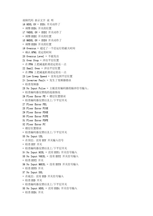
故障代码表示文字说明16 HDSL ON - SXD1 开关动作了- 调整SXD1 开关的位置17 VHDSL ON - SXD2 开关动作了- 调整SXD2 开关的位置18 MHDSL ON - SXD3 开关动作了- 调整SXD3 开关的位置19 Overrun - 超过了一个层运行的最大时间- 确认GPM1 设定的时间20 Overrun Level - 不能发出21 Over Stop - 冲出平层位置- 在PPM 上把减速距离设定的长一点22 Small Over - 冲出平层位置- 在PPM 上把减速距离设定的长一点23 Low Creep Speed - 没有达到平层位置24 Inverter Fault - 发生了变频器错误- 检查变频器25 No Input Pulse - 主板没有编码器的脉冲信号输入。
- 检查编码器反馈线的连接情况26 Floor Error PE - 楼层位置错误- 检查编码器反馈以及上/下平层开关27 Floor Error PEL28 Floor Error PUOE29 Floor Error PDOE30 Floor Error PUFE31 Floor Error PDFE32 Floor Error FC- 楼层位置错误- 检查编码器反馈以及上/下平层开关33 No Input USL- 在顶层,没有SXY 开关输入信号- 检查SXY 开关- 检查编码器反馈以及上/下平层开关34 No Input HUSL - 没有SXY1 开关信号输入35 No Input VHUSL - 没有SXY2 开关信号输入- 检查SXY2 开关36 No Input MHUSL - 没有SXY3 开关信号输入- 检查SXY3 开关37 No Input DSL- 在底层,没有SXD 开关信号输入- 检查SXD 开关- 检查编码器反馈以及上/下平层开关38 No Input HDSL - 没有SXD1 开关信号输入- 检查SXD1 开关39 No Input VHDSL - 没有SXD2 开关信号输入- 检查SXD2 开关40 No Input MHDSL - 没有SXD3 开关信号输入- 检查SXD3 开关SC-MCB系列电气调试手册宁波宏大电梯有限公司 Ningbo HongDa Elevator Co., Ltd. 第 38 页共 40 页故障代码表示文字说明41 No Input IUS - 没有输入上平层开关信号- 检查编码器反馈以及上平层开关42 No Input IDS - 没有输入下平层开关信号- 检查编码器反馈以及下平层开关43 No Input IUS/IDS - 上/下平层开关都没有输入信号- 检查编码器反馈以及上/下平层开关44 No Input DZONE- 没有输入门区开关信号- 不使用提前开门时在【OPT】上,把Door Zone SW 设定在【No】- 检查门区开关45 Not Off IUS - 上平层开关信号没有关闭- 检查上平层开关46 Not Off IDS - 下平层开关没有关闭- 检查下平层开关47 Not Off IUS/IDS - 上/下平层开关都没有关闭- 检查上/下平层开关48 Not Off DZONE - 门锁信号没有关闭- 检查门锁信号49 Failed leveling - 找不到平层。
宏大SC-MCB系统内部调试文件
SC-MCB系统内部调试文件文件号:1J0008006版本号:Ae5日期:2011.08OPP-2000 (操作器使用说明)1. OPP-2000产品概要1-1. 产品概要本产品是对电梯进行运行状态监示、变更运行模式及各种参数设定的小型手提操作器。
1-2. OPP-2000 外观图2.OPP-2000 菜单2-1. 主菜单在主菜单下,按【ENT】键两秒以上,进入项目选择菜单。
2-2. 项目选择菜单在OPP-2000所有的菜单操作上,按【ENT】键是设定,【ESC】键是取消或退出。
3. OPP-2000 菜单说明3-1. 主菜单固定菜单窗可变菜单窗信息窗3-1-1. 固定菜单窗1) MOD : 显示电梯运行模式(只读)- STARTUP : 系统运行准备中- INSPECTION : 检修运行模式- OPP INSPECTION : 操作器内部检修运行模式- CALIBRATION : 楼层高度测定模式- PARKING : 停梯模式- AUTO : 自动运行模式- OPP AUTO : 操作器自动运行模式- AUTO REPEAT : 反复运行模式- INDEPENDENT : 独立运行模式- ATTENDANT : 司机运行模式- FIREMAN CONTROL : 消防运行模式- EACH FLOOR STOP : 每站停运行模式- FIRE CONTROL : 火灾管制运行模式- SEISMIC VERY LOW : 地震管制运行模式- SEISMIC LOW : 地震管制运行模式- SEISMIC HIGH : 地震管制运行模式- UPS CONTROL : 停电管制运行模式- GENERATOR CONTROL : 发电机运行模式- MOVING HOUSE : 搬家运行模式2)FLR : 表示电梯现在所在的楼层3)DIR : 表示电梯运行方向,停止时表示为“-” M O D : A U T OF L R : 1 A C T : D o o r O p e n D R V : D r i v e O f f D A T : 1 9 9 8 / 0 4 / 2 7 M O N T I M : P m 0 5 : 4 0 : 5 5 D o o r s a r e o p e n i n gD I R : —4)ACT : 表示运行状态和错误记录- System Check : 系统检测中- Not Calibration : 没有楼层高度测定(自动运行一定需要楼层高度测定) - Run Up : 楼层高度测定中- Run Down : 电梯运行到最低层- Run Down DL : 为了测定楼层高度,电梯移动到DL(下限位开关) - Leveling : 电梯移动到最近层- Auto Stop : 开关门信号停止的状态- Ready : 关门待梯中- Acceleration : 加速运行中- High : 高速运行中- Deceleration : 减速运行中- Inspection Up : 检修上行运行中- Inspection Down : 检修下行运行中- Inspection Stop : 检修停止中- Door Open : 开门中- Door Close : 关门中- Door Stop SW On : 门机停止开关动作中- Emergency Stop : 紧急停止开关动作中- Control Finished : 停止、火灾、地震或停电等管制运行处理完毕- Group E-Stop : 群控指令停止5)DRV :表示电梯速度指令。
SC-MCB调试说明-Ae8(2013.3)
目 录第一章调试前的准备工作 (3)第二章主机自学习 (3)第三章慢车调试 (4)1.现场机械装配的检查及确认 (4)2.电气装配检查及确认 (4)3.通电检查 (5)4.开关门的调整 (7)5.机房紧急电动操作 (7)6.轿顶检修操作 (8)第四章快车调试 (8)1.现场机械装配的再次检查及确认 (8)2.电气装配的再次检查及确认 (9)3.电梯井道层楼自学习 (9)4.串行外呼板的调试方法: (9)第五章电梯试运行 (10)1.再平层功能运行 (10)2.单层运行 (10)3.多层运行 (10)4.开、关门运行的确认 (10)5.光幕功能的确认 (11)6指令登记及自保功能的确认 (11)7轿内误指令消除功能的确认 (11)8电梯平衡系数的确认 (11)9电梯轿内DOT-230M显示板中英文超载显示的设置 (12)10其它功能的确认(若无则无须确认) (12)第六章电梯平层及舒适感的调整 (13)1.平层位置的调整 (13)2.电梯起动舒适感的调整 (13)3.电梯停止时舒适感的调整 (14)附录一:变频器的操作说明 (15)1.施耐德频器(ATV71L) (15)2.艾默生变频器(CT‐ES) (23)3.乐邦变频器(LB90G) (27)附录二:主机自学习方法 (31)1.施耐德变频器(无齿同步电机) (31)2. 艾默生变频器 (33)附录三:变频器常见故障说明 (34)1.施耐德变频器(ATV71L) (34)2. 艾默生变频器(CT‐ES) (36)3. 乐邦变频器(LB90G) (38)附录四:MCU主板故障代码说明 (39)本调试说明书仅适用于我司配SC‐MCB系列的电气原理图,梯速在0.5M/S~2.5M/S之间。
第一章 调试前的准备工作1.调试人员中至少有一人能读懂本电梯的全部随机文件;2.调试人员必须熟悉变频变压调速电梯的原理、结构及操作方法;3.调试人员必须熟悉MCU主板的控制原理;4.调试人员必须具有熟练的故障判断、分析、排除能力;5.调试人员在调试过程中务必认真负责、细致周到、严格做好安全工作;6.调试所需仪器(一般情况下):a)万用表;b)转速表;c)直尺;d)常用电工工具;e)钳形表。
ALMCB调试指导书

调试指导书2013年5月目录1.产品介绍-------------------------------------------------------------------------------------------------------------------------- 11.1 产品名称 ------------------------------------------------------------------------------------------------------------------ 11.2 产品图片 ------------------------------------------------------------------------------------------------------------------ 21.3 产品结构 ------------------------------------------------------------------------------------------------------------------ 21.4 串行通信 ------------------------------------------------------------------------------------------------------------------ 92.工作条件-------------------------------------------------------------------------------------------------------------------------103.调试说明------------------------------------------------------------------------------------------------------------------------- 115.1 检修模式运行条件检查 ----------------------------------------------------------------------------------------------- 115.2 上电检查------------------------------------------------------------------------------------------------------------------ 115.3 驱动部分参数设置 -----------------------------------------------------------------------------------------------------135.4 驱动部分调试------------------------------------------------------------------------------------------------------------205.5 电梯运行方向检查 -----------------------------------------------------------------------------------------------------235.6 点动运行模式------------------------------------------------------------------------------------------------------------235.7 位置参考系统调整 -----------------------------------------------------------------------------------------------------245.8 首次正常运行准备 -----------------------------------------------------------------------------------------------------255.9 井道位置自学习---------------------------------------------------------------------------------------------------------255.10 正常运行 ----------------------------------------------------------------------------------------------------------------265.11. 正常运行的平层位置的调整---------------------------------------------------------------------------------------275.12 启动舒适感的调整----------------------------------------------------------------------------------------------------285.13 快车舒适感的调整(高速段低频抖动)------------------------------------------------------------------------285.14 ARD功能调试说明 ---------------------------------------------------------------------------------------------------28 4.逻辑功能和驱动参数表 ------------------------------------------------------------------------------------------------------306.1 逻辑参数及设置---------------------------------------------------------------------------------------------------------306.2 驱动参数设置及监控 --------------------------------------------------------------------------------------------------71 5.常见故障及排除方法 ---------------------------------------------------------------------------------------------------------767.1 常见逻辑故障表---------------------------------------------------------------------------------------------------------767.2 常见驱动故障表---------------------------------------------------------------------------------------------------------797.3 其它系统故障------------------------------------------------------------------------------------------------------------861. 产品介绍1.1 产品名称控制柜引用了ALMCB(逻辑控制板)作为电梯控制系统的核心,使用模块化设计技术,利用高可靠性的串行通讯系统,将电梯的各个部件紧密的连接在一起。
SB控制系统调试说明书
目 录序----------------------------------------------------------1 一. 电气线路连接及准备工作-----------------------------------2 二. 试上电及联机检查工作--------------------------------------2 三. 三轴读数头的位置调整--------------------------------------4 四. 通用参数设置--------------------------------------------------4 五. 各轴参数设置内容及相关提示信息 ---------------------11 六. 投入运行过程-------------------------------------------------15 七. 三轴 PID 参数优化方法及步骤---------------------------17 八. 手操器的参数设置-------------------------------------------19 九. 测头控制系统的调试----------------------------------------20 十. 更换 C NC0X 时的注意事项--------------------------------20SB控制系统调试说明书序三坐标测量机专用控制系统德国SB公司SB系列——德国先进技术和中国理念的完美结合——性能卓越、超强的抗干扰能力● 德国知名的三坐标测量机专用控制系统。
● 采用国际上先进的上、下位机式的双计算机控制系统。
● 支持多种侧头系统。
● 内置控制技术软件,可实现四轴伺服驱动及运动状态的优化调整。
● 具用伺服参数的调整可进行自动优化配置。
● 内含RENISHAW侧头控制器,可支持RENISHAW全系列侧头系统。
- 1、下载文档前请自行甄别文档内容的完整性,平台不提供额外的编辑、内容补充、找答案等附加服务。
- 2、"仅部分预览"的文档,不可在线预览部分如存在完整性等问题,可反馈申请退款(可完整预览的文档不适用该条件!)。
- 3、如文档侵犯您的权益,请联系客服反馈,我们会尽快为您处理(人工客服工作时间:9:00-18:30)。
SC-MCB系统内部调试文件文件号:1J0008006版本号:Ae5日期:2011.08OPP-2000 (操作器使用说明)1. OPP-2000产品概要1-1. 产品概要本产品是对电梯进行运行状态监示、变更运行模式及各种参数设定的小型手提操作器。
1-2. OPP-2000 外观图2.OPP-2000 菜单2-1. 主菜单在主菜单下,按【ENT】键两秒以上,进入项目选择菜单。
2-2. 项目选择菜单在OPP-2000所有的菜单操作上,按【ENT】键是设定,【ESC】键是取消或退出。
3. OPP-2000 菜单说明3-1. 主菜单固定菜单窗可变菜单窗信息窗3-1-1. 固定菜单窗1) MOD : 显示电梯运行模式(只读)- STARTUP : 系统运行准备中- INSPECTION : 检修运行模式- OPP INSPECTION : 操作器内部检修运行模式- CALIBRATION : 楼层高度测定模式- PARKING : 停梯模式- AUTO : 自动运行模式- OPP AUTO : 操作器自动运行模式- AUTO REPEAT : 反复运行模式- INDEPENDENT : 独立运行模式- ATTENDANT : 司机运行模式- FIREMAN CONTROL : 消防运行模式- EACH FLOOR STOP : 每站停运行模式- FIRE CONTROL : 火灾管制运行模式- SEISMIC VERY LOW : 地震管制运行模式- SEISMIC LOW : 地震管制运行模式- SEISMIC HIGH : 地震管制运行模式- UPS CONTROL : 停电管制运行模式- GENERATOR CONTROL : 发电机运行模式- MOVING HOUSE : 搬家运行模式2)FLR : 表示电梯现在所在的楼层3)DIR : 表示电梯运行方向,停止时表示为“-” M O D : A U T OF L R : 1 A C T : D o o r O p e n D R V : D r i v e O f f D A T : 1 9 9 8 / 0 4 / 2 7 M O N T I M : P m 0 5 : 4 0 : 5 5 D o o r s a r e o p e n i n gD I R : —4)ACT : 表示运行状态和错误记录- System Check : 系统检测中- Not Calibration : 没有楼层高度测定(自动运行一定需要楼层高度测定) - Run Up : 楼层高度测定中- Run Down : 电梯运行到最低层- Run Down DL : 为了测定楼层高度,电梯移动到DL(下限位开关) - Leveling : 电梯移动到最近层- Auto Stop : 开关门信号停止的状态- Ready : 关门待梯中- Acceleration : 加速运行中- High : 高速运行中- Deceleration : 减速运行中- Inspection Up : 检修上行运行中- Inspection Down : 检修下行运行中- Inspection Stop : 检修停止中- Door Open : 开门中- Door Close : 关门中- Door Stop SW On : 门机停止开关动作中- Emergency Stop : 紧急停止开关动作中- Control Finished : 停止、火灾、地震或停电等管制运行处理完毕- Group E-Stop : 群控指令停止5)DRV :表示电梯速度指令。
3-1-2. 可变菜单窗1)可变菜单窗表示各项开关输入和控制输出的状态等。
2)可变菜单窗是在初期画面下按【ESC】键两秒以上,变成可变菜单选择位置模式,由【▲】,【▼】键选择所需位置按【ENT】键,出来可变菜单选择窗。
这时用【▲】,【▼】键选择所需的表示项目,按【ENT】键,进入所选择的项目。
3)可变菜单窗说明。
- DAT : 表示今天的日期- TIM : 表示现在的时间- SPD : 表示系统最高运行速度- RPM : 表示马达的运行速度- PLS : 表示电梯现在所处在的位置,编码器的脉冲数- DSW : 表示主控板子上的DIP SW的设定状态*下面是系统运行状态的监控,ON 是运行, OFF是关闭- DORDOL : 未定义DCL : 未定义HCD : 未定义DOR : 门关着时 "ON"- IUDIUS : 表示平层上行开关的ON/OFF状态IDS : 表示平层下行开关的ON/OFF状态DOZ : 在使用门区(DOOR ZONE)开关的时候,表示门区开关的ON/OFF状态在不使用的时候“ON”表示在门区LEV : 电梯平层时“ON”- LT0UL : 表示UL(UP LIMIT)的ON/OFF状态USL : 表示USL(LONG RUN UP强制减速)的ON/OFF状态DSL : 表示DSL(LONG RUN DOWN强制减速)的ON/OFF状态DL : 表示DL(DOWN LIMIT)的ON/OFF状态- LT1HUS : 表示HUS(3 RUN UP强制减速)的ON/OFF状态VUS : 表示VUS(4 RUN UP强制减速)的ON/OFF状态VDS : 表示VDS(4RUN DOWN强制减速)的ON/OFF状态HDS : 表示HDS(3 RUN DOWN强制减速)的ON/OFF状态- LT2 :MUS : 表示MUS(5RUN UP强制减速)的ON/OFF状态SUS : 表示SUS(SHORT RUN UP强制减速)的ON/OFF状态SDS : 表示SDS(SHORT RUN DOWN强制减速)的ON/OFF状态MDS : 表示MDS(5 RUN DOWM强制减速)的ON/OFF状态- RSV :PAK : 表示锁梯运行的ON/OFF状态SCH : 表示自运回基站运行的ON/OFF状态EFS : 表示每站运行ON/OFF状态NSF : 未定义- OUT :OPN : 在有开门信号输出时ONCLS : 在有关门信号输出时ONACT : 在运行中ONBRK : 在抱闸开放状态时ON- DR2 :EOP : 在允许开门的状态下ONECL : 在允许关门的状态下ONF2D : 在消防运行状态时,DOOR COMMON信号输出时ONALD : 在平层状态时,DOOR COMMON信号输出时ON - DR3 :OP : 表示开门开关的ON/OFF状态HOP : 表示开放开关的ON/OFF状态AOP : 表示残障人开门开关的ON/OFF状态SFT : 表示安全门开关的ON/OFF状态- DR4 :PTO : 表示光电开关的ON/OFF状态OVL : 表示超载开关的ON/OFF状态DST : 表示门停止开关的ON/OFF状态ETC : 未定义* 下列是对输入输出端口的状态表示 1是“ON”, 0是“OFF”⑧⑦⑥⑤④③②①- IP0 : MCB-2003 Board 输入① : INS输入状态(1) 是检修模式 (0) 是正常模式② : IUP输入状态(检修上行开关)③ : IDN输入状态(检修下行开关)④ : IUS输入状态(上平层感应开关)⑤ : IDS输入状态(下平层感应开关)⑥ : DOL输入状态(开门限位开关)⑦ : DCL输入状态(关门限位开关)⑧ : 未定义- IP1 : MCB-2003 Board 输入① : 大厅和轿厢门机开关的输入状态② : 平层间感应开关的输入状态(DZONE)③ : 接触器监督开头输入状态(MK1K2)④ : 未定义⑤ : UL开关的输入状态(UP限位开关)⑥ : USL开关输入状态(2 RUN UP 限位开关)⑦ : HUSL开关的输入状态(3RUN UP限位开关)⑧ : VHUSL开关的输入状态(4RUN UP限位开关)- IP2 : MCB-2003 Board 输入① : MVHUSL开关的输入状态(5RUN UP限位开关)② : DL开关输入状态(DOWN限位开关)③ : DSL开关的输入状态(2RUN DOWN限位开关)④ : HDSL开关的输入状态(3RUN DOWN限位开关)⑤ : VHDSL开关的输入状态(4RUN DOWN限位开关)⑥ : MVHDSL开关的输入状态(5RUN DOWN限位开关)⑦ : PKS开关的输入状态(停车开关)⑧ : FIREMAN(RECALL)开关的输入状态(紧急呼叫开关,BS第二)- IP3 : MCB-2003 Board 输入① : 紧急停止开关的输入状态② : IOC的输入状态(变频器错误输入)③ : 停电管制运行输入状态④ : 抱闸输入状态(BRAKEM 输入)⑤ : 开门再平层,提前开门输入状态⑥ : 地震输入状态(SL输入)⑦ : 未定义⑧ : 火灾管制运行输入状态(FIRE输入,BS第一)- OP0 : MCB-2003 Board 输出① : 上行运行指令输出状态(FWD输出)② : 下行运行指令输出状态(REV输出)③ : 多段速指令X1输出状态(X1输出)④ : 多段速指令X2输出状态(X2输出)⑤ : 多段速指令X3输出状态(X3输出)⑥ : 多段速指令X4输出状态(X4(EXT1 输出)⑦ : 多段速指令X5输出状态(X5输出)⑧ : 变频器使能指令输出(RST输出)- OP1 : MCB-2003 Board 输出① : 开门信号输出(OP1输出)② : 关门信号输出(CL1输出)③ : 运行状态输出(ACT1,运行时ON)④ : 一般关门信号输出(CL2输出)⑤ : 残障人关门信号输出(CL3输出)⑥ : 强制关门(NUDGING CLOSE)信号输出(CL4输出)⑦ : 未使用⑧ : 未使用- OP2 : MCB-2003 Board 输出① : 变频器电源隔断信号输出状态(ICUT输出)② : 开门再平层,提前开门信号输出(DCOM输出)③ : 辅助刹车信号输出状态(BR1输出)④ : 刹车强制隔断信号输出(BRUCT输出)⑤ : 地震传感器再设定信号输出(EQRST输出)⑥ : Door Solenoid 信号输出状态(DSOL输出)⑦ : 接触器控制输出状态⑧ : DCOMR 输出状态(在使用Retreating CAM时,门强制Common输出)- BI0 : COB-101 Board 输入① : 未定义② : 未定义③ : 未定义④ : 安全门开关输入状态(SAFETY输入)⑤ : 超载开关输入状态(OVERLOAD输入)⑥ : 满载输入状态(FULL输入)⑦ : 未定义⑧ : 轻载开关输入状态(LOAD 30%开关输入)- BI1 : COB-101 Board 输入① : 未定义② : 司机运行时PASS开关输入状态(APASS输入)③ : 未定义④ : 司机运行下行开关输入状态(ADOWN输入)⑤ : 司机运行上行开关输入状态(AUP输入)⑥ : 选择司机运行开关输入状态(ATT输入)⑦ : 未定义⑧ : 未定义- BI2 : COB-101 Board 输入① : 门强制停止开关输入状态(DRST输入)② : 未定义③ : 未定义④ : 选择独立运行开关输入状态(IND输入)⑤ : 未定义⑥ : 未定义⑦ : 关门开关输入状态(CLOSE输入)⑧ : 开门开关输入状态(OPEN 输入)- BO0 : COB-101 Board 输出① : 未定义② : 未定义③ : 未定义④ : 未定义⑤ : 未定义⑥ : 未定义⑦ : 未定义⑧ : 未定义- BO1 : COB-101 Board 输出① : 蜂鸣器信号输出状态② : 上行到站钟信号输出状态③ : 下行到站钟信号输出状态 ④ : 风扇信号输出状态(电梯内部风扇)⑤ : 照明信号输出状态(电梯内部灯光)⑥ : 开门按钮的灯输出状态⑦ : 关门按钮的灯输出状态⑧ : 未定义3-2. 项目选择菜单3-2-1. 运行模式(MODE )菜单1)AUTO· 电梯自动响应轿内或外呼指令的运行模式。