L4000 智能控制器使用说明
K-49LVCN4000系列导电水位传感器控制器说明书
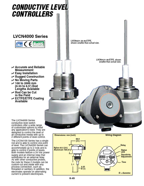
Electrodes: 316 SS Electrode Length: 100 to 2000 mm (3.9 to 6.5') Output Voltage of Electrodes: 12V to 100 Hz Weight: Approx. 2.7 kg (6 lb) for 1.2 m (4') Protection Class: NEMA 4 (IP65)
metallic tank wall or another rod for non-metallic tanks.
Options
Ordering Suffix
Description
A-Process Connection
1
1⁄2 NPT thread
2
3⁄4 NPT thread
3
1 NPT thread
LVCN42(A)(B)-(C) Custom conductive level controller, dual rod, select process connection (A), enclosure (B), and rod length in inches (C)
* Rods must be coated when using the probes above 82°C (180°F). All conductive applications must have a reference point, such as the
Specifications
Power Supply: 24 Vdc (±10%) Current Consumption: Maximum 2 VA Temperature Range:
316 SS: -10 to 82°C (-14 to 180°F) ETFE: -10 to 120°C (-14 to 248°F) Maximum Pressure: 290 psi (20 bar) Wetted Materials: 316 SS Enclosure Material: Glass-filled nylon standard, aluminum optional
智能控制器使用手册

智能控制器使用手册一概述智能控制器是框架式空气断路器的核心部件,适用于50~60Hz电网,主要用作配电、馈电或发电保护,使线路和电源设备免受过载、短路、接地/漏电、电流不平衡、过压、欠压、电压不平衡、过频、欠频、逆功率等故障的危害;通过负载监控,需量保护,区域连锁等功能实现电网的合理运行。
同时也用作电网节点的电流、电压、功率、频率、电能、需量、谐波等电网参量的测量;故障、报警、操作、电流历史最大值、开关触头磨损情况等运行维护参数的记录;当电力网络进行通讯组网时,智能控制器可用为电力自动化网络的远程终端实现遥测,遥信,遥控,遥调等,智能控制器支持多种协议以适用不同的组网要求。
二基本功能对于M型无任何可选功能(加*的项目)时其功能配置为基本功能,如表1所示:表1 基本功能配置2.1.3 通讯功能通讯功能为可选项,对于M型没有通讯功能,对于H 型通讯协议可根据需要选择为Modbus,Profibus-DP,Device net.2.1.4增选功能选择增选功能为可选项,M型,H型都可以选择增选功能配置,不同增选功能代号与增选功能内容如表2所示。
表2 增选功能配置表2.1.5 区域连锁及信号单元的选择“区域连锁及信号单元”为可选项,M型、H型都可以选择信号单元的功能配置,当信号单元选择为S2,S3时,控制器具备区域连锁功能。
2.2 技术性能2.2.1 适用环境工作温度:-10℃~+70℃(24h•内平均值不超过+35℃)储存温度:-25℃~+85℃安装地点最湿月的月平均最大相对湿度不超过90%,同时该月的月平均最低温度不超过+25℃,允许由于温度变化产生在产品表面的凝露。
污染等级:3级。
(在和断路器装配在一起的情况下)安装类别:Ⅲ。
(在和断路器装配在一起的情况下)2.2.2工作电源由辅助电源和电源互感器同时供电,保证负载很小和短路情况下控制都可以可靠工作。
控制器的供电方式有下面3种方式:a.电源CT供电额定电流大于等于400A时,一次电流单相不低于0.4In,三相不低于0.2In时控制器正常工作。
L4000 智能控制器使用说明

L-4000智能控制器使用说明L4000智能控制器基本参数工作电压:220V外型尺寸:390*235*80 (H*W*D)最大负载:6000W单路负载:可调灯光1500W 开关灯光3000W功能简介L-4000灯光/空调智能控制器是专为KTV设计的一款具备灯光亮度调节、中央空调控制、可编程的智能型灯光/空调控制器。
1、设有6路大功率可调光及4路大功率继电器,满足各种灯光应用的需求2、可直接通过串口与机顶盒或电脑连接3、可直接连接灯光控板,脱离点歌系统及中控盒独立运行4、可对任一模式下的灯光状态进行编程,实现任意灯光搭配5、灯光控制器上可直接按键操作选择灯光模式及调节灯光亮度6、灯光亮度均衡,通过在不同模式下设置不同的亮度,实现场景效果切换,减少了灯光的开关次数,延长灯光使用寿命7、可外接遥控器对灯光进行遥控控制(选配)8、中央空调智能控制,配合点歌系统可实现远程开关空调9、配盒空调墙板通过温度探测,可智能控制风机及阀门的开关,减少能源浪费10、设有2组空调控制11、根据室温与设定温的比对,自动调节风速12、采用串口光电隔离技术,避免设备间的互相干扰灯光控制的设置一、灯光模式对应组的编程先关闭灯光控制器电源,按住设置及确认键不放,打开电源,等待约1秒,灯光控制器显示01并闪烁,表示01组,按△或▽键选择所要编程的组。
1、选择需要编程的组按△或▽键选择需要编程的组,按确认键进入该组编程设置;2、设置该组对各路灯光的控制状态数码管显示J1,对应指示灯指示出该模式下灯光的控制状态,亮表示控制,闪烁表示不控制,不亮表示强制关。
按▽键选择要设置的灯光,J1-JA表示灯光控制器的10路,按设置键进行设置,按确认键进入下一步设置;3、设置组的开关模式显示H1表示固定模式,显示H0表示开关模式(固定模式:例如,当按K歌时1、2、3路亮,再次按K歌时还是1、2、3路亮;开关模式:例如,当按K歌时1、2、3路亮,再次按K歌时1、2、3路灭),按设置键进行选择,按确认键进入下一步设置;4、设置组的亮度继承方式显示L1表示固定亮度,显示L0表示继承亮度(固定亮度,例如:进入K歌模式后,将其亮度由60调到80,第二次进入K歌模式时它的默认亮度还原为60;继承亮度,例如:进入K歌模式后,将其亮度由60调到80,第二次进入K歌模式时它的默认亮度为80)。
IR4000系列压力调节器产品说明说明书

Value Proposition:The IR4000 Series regulator offers high pressure capability with an inlet pressure up to 4,000 psig. Its large, convoluted Hastelloy ® C-22 diaphragm provides stable pressure control and corrosion resistance. Close tolerances and tight alignment of moving components minimize hysteresis and improve cycle life.IR4000 SeriesSingle-Stage, General Purpose Pressure RegulatorInternal Threadless • Stainless SteelProduct Features:• U nique compression member loads the seal to the body without requiring a threaded nozzle or additional seals • Internally threadless design reduces particle generation; low internal volume reduces purge times • Positive upward and downward stops increase cycle life by preventing over stroking of the diaphragm •Selection of seat materials for media compatibility and temperature applicationsINSTRUMENTATION PRODUCTS DIVISIONSpecifications:For additional information on materials of construction, functional performance and operating conditions, please contact factory.Hastelloy ® is a registered trademark of Haynes International, Inc.PEEK™ is a trademark of Victrex plc.Vespel ® is a registered trademark of DuPont Performance Elastomers L.L.C.Inconel ®is a registered trademark of Special Metals Corporation2IR4000 Series Lit.# 25000226 03/18Instrumentation Products Division2468101214O u t l e t P r e s s u r e (p s i g )N 2 Flow (slpm) IR4000 .06 C V10203040506070O u t l e t P r e s s u r e (p s i g )N 2 Flow (slpm)IR4002 .06 C V102030405060708090100110120O u t l e t P r e s s u r e (p s i g )N 2 Flow (slpm)IR4003 0.15 CWhen setting the delivery pressure,ensure that the maximum outlet pressure of the regulator is not exceeded for any operating condition including increases in delivery pressure due to flow shutoff and supply pressure effect. Supply pressure effect will result in a significant rise in outlet pressure as the inlet pressure decreases.The stop settings will be adjusted to accommodate typical inlet and outlet pressure ranges. Please contact the factory if specific stop settings are required.Flow Curve:*1,250 max. pressure for PEEK and Vespel seatsOrdering Information:IR4000 Series Lit.# 25000226 03/18Instrumentation Products DivisionOffer of SaleThe items described in this document are available for sale by Parker Hannifin Corporation, its subsidiaries or its authorized distributors. Any sale contract entered by Parker will begoverned by the provisions stated in Parker's standard terms and conditions of sale (copy available upon request).©2018 Parker Hannifin Corporation | Instrumentation Products Division Literature #: 25000226 Mar 2018Parker WorldwideAE – UAE, Dubai Tel: +971 4 8875600********************AR – Argentina, Buenos Aires Tel: +54 3327 44 4129******************AT – Austria, Wiener Neustadt Tel: +43 (0)2622 23501-0*************************AT – Eastern Europe, Wiener NeustadtTel: +43 (0)2622 23501 970****************************AU – Australia, Dandenong Tel: +61 (0)3 9768 5555******************************AZ – Azerbaijan, Baku Tel: +994 50 2233 458****************************BE/LX – Belgium, Nivelles Tel: +32 (0)67 280 900*************************BR – Brazil, Sao Jose dos Campos Tel: +55 12 4009 3504******************BY – Belarus, Minsk Tel: +375 17 209 9399*************************CA – Canada, Grimsby, Ontario Tel +1 905-945-2274*********************CH – Switzerland, Etoy Tel: +41 (0) 21 821 02 30*****************************CL – Chile, Santiago Tel: +56 (0) 2 2303 9640******************CN – China, Shanghai Tel: +86 21 2899 5000*****************************CZ – Czech Republic, Klecany Tel: +420 284 083 111*******************************DE – Germany, Kaarst Tel: +49 (0)2131 4016 0*************************DK – Denmark, Ballerup Tel: +45 43 56 04 00*************************ES – Spain, Madrid Tel: +34 902 33 00 01***********************FI – Finland, VantaaTel: +358 (0)20 753 2500*************************FR – France, Contamine s/Arve Tel: +33 (0)4 50 25 80 25************************GR – Greece, Athens Tel: +30 210 933 6450************************HU – Hungary, Budapest Tel: +36 1 220 4155*************************ID – Indonesia, Tangerang Tel: +62 (0)21 7588 1906********************IE – Ireland, DublinTel: +353 (0)1 466 6370*************************IN – India, MumbaiTel: +91 22 6513 7081-85IT – Italy, Corsico (Ml)Tel: +39 02 45 19 21***********************JP – Japan, Tokyo Tel: +(81) 3 6408 3900******************KR – South Korea, Seoul Tel: +82 2 559 0400*******************KZ – Kazakhstan, Almaty Tel: +7 7272 505 800****************************LV – Latvia, Riga Tel: +371 6 745 2601************************MX – Mexico, Toluca Tel: +52 722 275 4200*******************MY – Malaysia, Selangor Tel: +603 784 90 800*******************NL – The Netherlands, Oldenzaal Tel: +31 (0)541 585 000********************NO – Norway, Stavanger Tel: +47 (0)51 826 300************************NZ – New Zealand, Mt Wellington Tel: +64 9 574 1744PL – Poland, Warsaw Tel: +48 (0)22 573 24 00************************PT – Portugal, Leca da Palmeira Tel: +351 22 999 7360**************************RO – Romania, Bucharest Tel: +40 21 252 1382*************************RU – Russia, Moscow Tel: +7 495 645-2156************************SE – Sweden, Spånga Tel: +46 (0)8 59 79 50 00************************SG – Singapore,Tel: +65 6887 6300*******************SK – Slovakia, Banská Bystrica Tel: +421 484 162 252**************************SL – Slovenia, Novo Mesto Tel: +386 7 337 6650**************************TH – Thailand, Bangkok Tel: +66 2 186 7000*********************TR – Turkey, Istanbul Tel: +90 216 4997081************************TW – Taiwan, Taipei Tel: +886 2 2298 8987*************************UA – Ukraine, Kiev Tel: +380 44 494 2731*************************UK – United Kingdom, Warwick Tel: +44 (0)1926 317878********************USA – IPD, Huntsville Tel: +1 256 881 2040*****************USA – Autoclave Engineers, Erie Tel: +1 814 860 5700*******************VN – Vietnam, Hochi Minh City Tel: +84 (0)8337 546 51**********************ZA – South Africa, Kempton Park Tel: +27 (0)11 961 0700*****************************WARNINGFAILURE, IMPROPER SELECTION OR IMPROPER USE OF THE PRODUCTS AND/OR SYSTEMS DESCRIBED HEREIN OR RELATED ITEMS CAN CAUSE DEATH,PERSONAL INJURY AND PROPERTY DAMAGE.This document and other information from Parker Hannifin Corporation, its subsidiaries and authorized distributors provide product and/or system options for further investigation by users having technical expertise. It is important that you analyze all aspects of your application and review the information concerning the product or system in the current product catalog. Due to the variety of operating conditions and applications for these products or systems, the user, through its own analysis and testing, is solely responsible for making the final selection of the products and systems and assuring that all performance, safety and warning requirements of the application are met. The prod-ucts described herein, including without limitation, product features, specifications, designs, availability and pricing, are subject to change by Parker Hannifin Corporation and its subsidiaries at any time without notice.Proposition 65 Warning: This product contains chemicals known to the state of California to cause cancer or birth defects or other reproductive harm.Instrumentation Products Division 1005 A Cleaner WayHuntsville, AL 35805 • USA Tel: 256 881 2040Fax: 256 881 5072******************** /ipdMobile Application: /ipdIR4000 SERIES: Single Stage, General Purpose Pressure Regulator。
发电机智能控制器操作

目录1.概述22.控制器外形结构与连线23.操作面板64.安装指南75.控制与操作说明76.测量显示数据97.警告和停机故障108.参数设置119.LCD显示和菜单系统1410.通讯功能1611.控制器启用前的准备工作2012.技术参数211 .概述:ACCESS4000X智能控制器是由一个微电脑处理器作为柴油发电机组的主要控制系统。
此控制器采用了最先进的电脑线路板,同时提供了强大而操作简单的系统,它集测量、控制、保护、四遥等众多功能于一体,完全满足发电机使用者或专业组装厂对不同类型的发电机组自动控制需求。
控制器测量显示发电机输出的所有电参数,采用真有效值测量,确保数据更准确。
中英文菜单选择,大屏幕LCD显示各测量参数和状态。
多至16组类比式或数位式故障讯号输入。
所有启动及停机执行程序、机组运作状态及故障保护状态等功能都可以显示于控制器上。
当发电机组发生了紧急的故障,发电机组会立刻停机作保护,20组故障记录,设定参数内容不会流失。
一系列的选择性配套可供客户选择,通讯协议完全公开及RS-485通讯接口,可以达到中央监控系统要求BMS或SCADA监控系统,亦可配备遥距监测状态传导器作机组状态监测。
控制器模块是使用坚固的铁壳作为外壳,安装于控制屏的屏面上。
控制器的所有连线都通过针式带锁的端子连接,令设备的连线、移动、维修、更换非常容易和方便。
2 .控制器外形结构与连线:2.1详细尺寸如下:本说明书只适用卜ACCESS4 Hill X发电机智能控制器,凡使用者必须先详阅本说明书。
操作面板W280mmH215mm安装开孔口W250mH185m厚度D65.5mm(未连线)ACCESS4000X 280X)用。
E2.2接线端口:控制器“D/C”直流接线端控制器“RS485”通讯接线端23典型接线图:i ncx-g*>p*lx¥ucm,•二”・p口X。
口222.nn D<"BJr«!o i23g>-<-8:48:ETr-一E“gw jg:3JP¥^-J Alw—IX93』夕革”§▼S8Ss SME,岑F u8G Mn?•X En y cj d?A3M«d Au?cAT-4mU4Am3操作面板整个操作面板分三部分:测量参数LCD显示、操作开关和运行状态发光二极管指示。
Omega CN4000系列温度控制器用户指南说明书

e-mail:**************For latest product manuals: CN4000 SERIESTemperature ControllersShop online at User’s G ui d e***********************Servicing North America:U.S.A. Omega Engineering, Inc.Headquarters: Toll-Free: 1-800-826-6342 (USA & Canada only)Customer Service: 1-800-622-2378 (USA & Canada only)Engineering Service: 1-800-872-9436 (USA & Canada only)Tel: (203) 359-1660 Fax: (203) 359-7700e-mail:**************For Other Locations Visit /worldwideThe information contained in this document is believed to be correct, but OMEGA accepts no liability for any errors it contains, and reserves the right to alter specifications without notice.CONTENTSMODEL CONFIGURATION (2)SPECIFICATIONS (3)PARAMETER AND SETTING (4)SYMBOL DESCRIPTIONS (7)INSTRUMENT INSTALLATION AND WIRING (8)DISPLAY AND OPERATIONS (9)OPERATION DESCRIPTION (10)MODEL CONFIGURATIONModel DescriptionCN4116 (*)-(**)-(***) 1/16 DIN controllerCN4216 (*)-(**)-(***) 1/16 DIN controller, with 0.0 decimalCN414 (*)-(**)-(***) 1/4 DIN controllerCN424 (*)-(**)-(***) 1/4 DIN controller, with 0.0 decimalCN418V (*)-(**)-(***) 1/8 DIN Vertical controllerCN428V (*)-(**)-(***) 1/8 DIN Vertical controller, with 0.0 decimalCN418H (*)-(**)-(***) 1/8 DIN Horizontal controllerCN428H (*)-(**)-(***) 1/8 DIN Horizontal controller, with 0.0 decimal*Specify controlling output code from Output Options table below**Specify alarm code from Alarm Options table below***Low voltage power supply option (-LV)Controlling Output OptionsOption Type CodeRelay -R1DC SSR driver -DC1Alarming Output OptionsOption Type CodeRelay -R2DC SSR driver -DC2Low voltage power supply optionHz50/60AC/DC,-LV 24VSPECIFICATIONSThermocouple RTD Input TypeK S R E J N PT100Range ℃/ ℉0 to1300 ℃32 to 2372 ℉0 to1700℃32 to 3092 ℉0 to1600℃32 to 2412 ℉0 to1000℃32 to 1832 ℉0 to1200℃32 to 2192 ℉0 to 1300℃32 to 2372 ℉-200 to 800℃-328 to 1472 ℉Accuracy:CN 4116/CN414/CN4180.3%FS ± 1℃/1.8°FCN4216/CN424/CN428 0.3%FS ± 0.1℃/0.18°FTemperature Display ResolutionCN 4116/CN414/CN4181℃/1℉CN4216/CN424/CN4280.1℃/0.1℉ON / OFF ControlControl MethodAI PID Control with Auto Tuning (AT)Relay Output (1A/250VAC)Output TypeVoltage Output for SSR(12V/30mA)Limit High / LowAlarm(Modularization) High deviation/Low deviation100~240VAC (-15%, +10%), or 24VDC Supply Voltage50 to 60HzPower Consumption ≦ 3WOperating EnvironmentsTemperature: -10 to +60℃ / 14 to 140℉Humidity: 0~90RH%Electromagnetic compatibility (EMC) IEC61000-4-4: ± 4KV/5KHz IEC61000-4-5: 4KVPARAMETER AND SETTINGField parameter table (Primary parameters)Code Description Remarks SettingRange DefaultHIAL High limit alarm Alarm on when PV>HIALalarm off when PV<HIAL- AHYS-999~+3000 3000LoAL Low limit alarm Alarm on when PV<LoAL;alarm off when PV>LoAL + AHYS-999~+3000 -999HdAL Deviation highalarmAlarm on when PV-SV>HdAL;alarm off when PV-SV<HdAL - AHYS-999~+3000 3000LdAL Deviation lowalarmAlarm on when PV-SV<LdAL;alarm off when PV-SV>LdAL + AHYS-999~+3000 -999Loc Parameter LockLocAutoTuningSVPrimaryParameterSecondaryParameter0 X1 X X2 X X X3 X X X X808: allow to modify data or execute ATX : not allow to modify data or execute AT0~255 0System parameter table (Secondary parameters)Scb Input Shift Parameter Scb is used to make input shift tocompensate the error produced by sensor or inputsignal itself.PV-after-compensation=PV-before-compensation + Scb.-199~+400FILt PV input filter The value of FILt will determine the ability offiltering noise.When a large value is set, the measurement inputis stabilized but the response speed is slow.Generally, if great interference exists, then youcan increase parameter “FILt” gradually to makemomentary fluctuation of measured value lessthan 2 to 5.When the meter of the instrument is beingexamined at laboratory, “FILt” should be set to 0or 1 to short the response time.0~40 1Fru Selection of powerfrequency andtemperature scale50C: 50Hz, ℃50F: 50Hz, ℉60C: 60Hz, ℃60F: 60Hz, ℉50C, 50F,60C, 60F50CSPL Low limit of SV -999~3000SPH Upper limit of SV -999~3000400SYMBOL DESCRIPTIONS Symbol DescriptionorAL Input specification setting is incorrectOrInput wiring is disconnected/ thermocouple problem OrShort circuitedHIAL High limit alarm LoAL Low limit alarm HdAL Deviation high alarm LdAL Deviation low alarm EErr IC Software error 8888 IC Software errorINSTRUMENT INSTALLATION AND WIRINGWiring graph for instruments with dimension 1/4 DIN; 1/8 DIN Vertical and HorizontalNote: The compensation wires for different kinds of thermocouple are different, and should be directly connect to the terminals. Connecting the common wire between the compensation wire and the t e r m i n a l s w i l l c a u s e m e a s u r e m e n t e r r o r.Wiring graph for 1/16 DIN dimension instruments :DISPLAY AND OPERATIONS①Upper display window, displays PV,parameter code, etc.②Lower display window, displays SV,parameter value, or alarm③Setup key, for accessing parametertable and conforming parametermodification.④Data shift key, and auto tuning.⑤Data decrease key⑥Data increase key⑦LED indicator. MAN, PRG, MIO,COM, OP2, AL2, AU1 and AU2Com indicators is non-applicable.OP1 and AL1 will indicate I/O operation of the corresponding module.Basic display status:When power on, the upper display window of the instrument shows the process value (PV), and the lower window shows the set-point (SV). This status is called basic display status.When the input signal is out of the measurable range (for example, the thermocouple or RTD circuit is break, or input specification sets wrong), the upper display window will alternately display “orAL” and the high limit or the low limit of PV, and the instrument will automatically stop output. If the lower display window alternately display “HIAL”, “LoAL”, “HdAL” or “LdAL”, it means high limit alarm, low limit alarm, deviation high alarm, and deviation low alarm happening.OPERATION DESCRIPTIONz Set Value Setting:In basal display status, if the parameter lock “Loc” isn't locked, we can set setpoint (SV) by pressing 、 or . Press key to decrease the value, key to increase the value, and key to move to the digit expected to modify. Keep pressing or , the speed of decreasing or inscreasingvalue get quick. The range of setpoint is between the parameter SPL and SPH.The default range is 0~400.z Parameter Setting:In basal display status, press and hold for about 2 seconds can accessField Parameter Table. Pressing can go to the next parameter; pressing 、 or can modify a parameter. Press and hold can return tothe preceding parameter. Press (don't release) and then press key simultaneously can escape from the parameter table. The instrument will escape auomatically from the parameter table if no key is pressed within 30 seconds. Setting Loc=808 and then press can access System Parameter Table.●AI artificial intelligence control and auto tuningWhen AI artificial intelligence control method is chosen (CtrL=APId), the PID parameters can be obtained by running auto-tuning. In basal display status,press for 2 seconds, the “At” parameter will appear. Press to changethe value of At from “oFF” to “on”, then press to active the auto-tuning process. During auto tuning, the instrument executes on-off control. After 2-3 times of on-off action, the instrument will obtain the optimal control parametervalue. If you want to escape from auto tuning status, press and hold thekey for about 2 seconds until the "At" parameter appear again. Change “At”from “on” to “oFF”, press to confirm, then the auto tuning process will be cancelled.Note 1: If the setpoint is different, the parameters obtained from auto-tuning are possible different. So you’d better set setpoint to an often-used value ormiddle value first, and then start auto-tuning. For the ovens with goodheat preservation, the setpoint can be set at the highest applicabletemperature. Depending on the system, the auto-tuning time can befrom several seconds to several hours.Note 2: Parameter Ctl (on-off differential, control hysteresis) has influence on the accuracy of auto-tuning. Generally, the smaller the value of Ctl, thehigher the precision of auto tuning. But Ctl parameter value should belarge enough to prevent the instrument from error action around setpointdue to the oscillation of input. Ctl is recommended to be 2.0.Note 3: The instrument has the function of self-learning. It is able to learn the process while working. The control effect at the first run after auto tuningis probably not perfect, but excellent control result will be obtained after aperiod of time because of self-learning.10OMEGA’s policy is to make running changes, not model changes, whenever an improvement is possible. T his affords our customers the latest in technology and engineering.OMEGA is a trademark of OMEGA ENGINEERING, INC.© Copyright 2018 OMEGA ENGINEERING, INC. All rights reserved. T his document may not be copied, photocopied, reproduced, translated, or reduced to any electronic medium or machine-readable form, in whole or in part, without the prior written consent of OMEGA ENGINEERING, INC.FOR WARRANTY RETURNS, please have the following information available BEFORE contacting OMEGA:1. P urchase Order number under which the product was PURCHASED,2. M odel and serial number of the product under warranty, and3. Repair instructions and/or specific problems relative to the product.FOR NON-WARRANTY REPAIRS, consult OMEGA for current repair charges. Have the following information available BEFORE contacting OMEGA:1. Purchase Order number to cover the COST of the repair,2. Model and serial number of the product, and 3. Repair instructions and/or specific problems relative to the product.RETURN REQUESTS/INQUIRIESDirect all warranty and repair requests/inquiries to the OMEGA Customer Service Department. BEFORE RET URNING ANY PRODUCT (S) T O OMEGA, PURCHASER MUST OBT AIN AN AUT HORIZED RET URN (AR) NUMBER FROM OMEGA’S CUST OMER SERVICE DEPART MENT (IN ORDER T O AVOID PROCESSING DELAYS). The assigned AR number should then be marked on the outside of the return package and on any correspondence.T he purchaser is responsible for shipping charges, freight, insurance and proper packaging to preventbreakage in transit.WARRANTY/DISCLAIMEROMEGA ENGINEERING, INC. warrants this unit to be free of defects in materials and workmanship for a period of 25 months from date of purchase. OMEGA’s WARRANTY adds an additional one (1) month grace period to the normal two (2) year product warranty to cover handling and shipping time. This ensures that OMEGA’s customers receive maximum coverage on each product.If the unit malfunctions, it must be returned to the factory for evaluation. OMEGA’s Customer Service Department will issue an Authorized Return (AR) number immediately upon phone or written request. Upon examination by OMEGA, if the unit is found to be defective, it will be repaired or replaced at no charge. OMEGA’s WARRANT Y does not apply to defects resulting from any action of the purchaser, including but not limited to mishandling, improper interfacing, operation outside of design limits, improper repair, or unauthorized modification. T his WARRANT Y is VOID if the unit shows evidence of having been tampered with or shows evidence of having been damaged as a result of excessive corrosion; or current, heat, moisture or vibration; improper specification; misapplication; misuse or other operating conditions outside of OMEGA’s control. Components in which wear is not warranted, include but are not limited to contact points, fuses, and triacs.OMEGA is pleased to offer suggestions on the use of its various products. However, OMEGA neither assumes responsibility for any omissions or errors nor assumes liability for any damages that result from the use of its products in accordance with information provided by OMEGA, either verbal or written. OMEGA warrants only that the parts manufactured by the company will be as specified and free of defects. OMEGA MAKES NO OTHER WARRANTIES OR REPRESENTATIONS OF ANY KIND WHATSOEVER, EXPRESSED OR IMPLIED, EXCEPT THAT OF TITLE, AND ALL IMPLIED W ARRANTIES INCLUDING ANY W ARRANTY OF MERCHANTABILITY AND FITNESS FOR A PARTICULAR PURPOSE ARE HEREBY DISCLAIMED. LIMITATION OF LIABILITY: The remedies of purchaser set forth herein are exclusive, and the total liability of OMEGA with respect to this order, whether based on contract, warranty, negligence, indemnification, strict liability or otherwise, shall not exceed the purchase price of the component upon which liability is based. In no event shall OMEGA be liable for consequential, incidental or special damages.CONDITIONS: Equipment sold by OMEGA is not intended to be used, nor shall it be used: (1) as a “Basic Component” under 10 CFR 21 (NRC), used in or with any nuclear installation or activity; or (2) in medical applications or used on humans. Should any Product(s) be used in or with any nuclear installation or activity, medical application, used on humans, or misused in any way, OMEGA assumes no responsibility as set forth in our basic WARRANT Y /DISCLAIMER language, and, additionally, purchaser will indemnify OMEGA and hold OMEGA harmless from any liability or damage whatsoever arising out of the use of theProduct(s) in such a manner.Where Do I Find Everything I Need forProcess Measurement and Control?OMEGA…Of Course!Shop online at TEMPERATUREM U Thermocouple, RTD & Thermistor Probes, Connectors,Panels & AssembliesM U Wire: Thermocouple, RTD & ThermistorM U Calibrators & Ice Point ReferencesM U Recorders, Controllers & Process MonitorsM U Infrared PyrometersPRESSURE, STRAIN AND FORCEM U Transducers & Strain GagesM U Load Cells & Pressure GagesM U Displacement TransducersM U Instrumentation & AccessoriesFLOW/LEVELM U Rotameters, Gas Mass Flowmeters & Flow ComputersM U Air Velocity IndicatorsM U Turbine/Paddlewheel SystemsM U Totalizers & Batch ControllerspH/CONDUCTIVITYM U pH Electrodes, Testers & AccessoriesM U Benchtop/Laboratory MetersM U Controllers, Calibrators, Simulators & PumpsM U Industrial pH & Conductivity EquipmentDATA ACQUISITIONM U Communications-Based Acquisition SystemsM U Data Logging SystemsM U Wireless Sensors, Transmitters, & ReceiversM U Signal ConditionersM U Data Acquisition SoftwareHEATERSM U Heating CableM U Cartridge & Strip HeatersM U Immersion & Band HeatersM U Flexible HeatersM U Laboratory HeatersENVIRONMENTALMONITORING AND CONTROLM U Metering & Control InstrumentationM U RefractometersM U Pumps & TubingM U Air, Soil & Water MonitorsM U Industrial Water & Wastewater TreatmentM U pH, Conductivity & Dissolved Oxygen InstrumentsM4545/0418。
DEC-1000和DEC-4000控制器操作说明书讲述
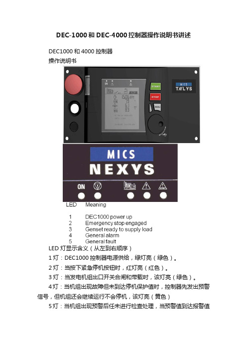
DEC-1000和DEC-4000控制器操作说明书讲述DEC1000和4000控制器操作说明书LED 灯显示含义(从左到右顺序)1灯:DEC1000控制器电源供给,绿灯亮(绿色)。
2灯:当按下紧急停机按钮时,红灯亮(红色)。
3灯:当发电机组出口开关合闸和带载时,该灯亮(绿色)。
4灯:当机组出现故障但未到达停机保护值时,控制器先发出预警信号,但机组还会继续运行不会停机,该灯亮(黄色)5灯:当机组出现预警后任未进行检查处理,当预警值到达报警值时,机组立即自动停止运行进行保护,该灯亮(红色)当机组运行时,RPM:显示机组运转的速度(1500转/分);同时显示机组运行时,充电机输出电压值:13.6V(直流)。
显示:控制器运行累计时间:23589小时;显示:发电机组输出电源频率:50Hz;显示:电池电压13.6V显示:柴油量在油箱的百分比值:37%显示:冷却液温度:85℃(水温)显示:机组运行中机油压力:3.2BAR以上为公制单位显示:柴油量在油箱的百分比值:37%显示:冷却液温度:85F(水温)显示:机组运行中机油压力:40-60PSI以上为英制单位显示:L1-L2相电压:404V;显示:L2-L3相电压:403V;显示:L3-L1相电压:401V显示:L1-N线电压233V;显示:L2-N线电压233V;显示:L3-N线电压232V.显示:L1相电流530A显示:L2相电流537A显示:L3线电流548A机侧启动1、将控制器上钥匙开关从左侧向右侧旋转,打开控制器电源,控制指示灯亮及液晶屏出现文字显示,控制器并读取程序;2、控制器绿色灯亮,说明机组无故障,准备就绪;3、按下“START”绿色按钮,机组立即进行预热10秒,10秒后机组立即启动,机组启动成功允许;4、读取机组允许参数:按下“左侧白色按钮”,每按一次,显示一组参数,其中参数包括:发动机转速、水温、机油压力、3相电压及频率、3相电流、电池电压等;5、按下“STOP”按钮,机组立即停止运转。
Philips 超自动咖啡机4000系列使用指南说明书

s lLeer atentamente antes de utilizar la máquina.Registre su producto y obtenga asistencia en/welcomeMáquina de café exprés superautomática4000 series INSTRUCCIONES DE USO HD8844E S05053Ajuste de la salida de café (27)Ajuste de la cantidad de café en taza (28)SUMINISTRO DE CAFÉ EXPRÉS Y CAFÉ EXPRÉS LARGO (29)Suministro de café exprés y café exprés largo con café en grano (29)Suministro de café exprés y café exprés largo con café premolido (30)SUMINISTRO DE CAFÉ LARGO (CLASSIC COFFEE) (31)Suministro de café largo (Classic Coff ee) con café en grano (31)Suministro de café largo (Classic Coff ee) con café premolido (32)CÓMO ESPUMAR LECHE Y PREPARAR UN CAPUCHINO (34)Cómo espumar leche (34)Cómo preparar un capuchino (37)SUMINISTRO DE AGUA CALIENTE (37)LIMPIEZA Y MANTENIMIENTO (39)Limpieza diaria de la máquina (39)Limpieza semanal de la máquina (41)Limpieza del depósito de agua (41)Limpieza diaria del Montador de leche Automático (42)Limpieza mensual del Montador de leche Automático (43)Limpieza semanal del grupo de café (49)Lubricación mensual del grupo de café (52)Limpieza mensual del grupo de café con pastillas desengrasantes (54)Limpieza mensual del contenedor de café en grano (56)DESCALCIFICACIÓN (57)Fase de preparación (57)Fase de descalcifi cación (59)Fase de enjuague (60)Interrupción del ciclo de descalcifi cación (63)PROGRAMACIÓN (64)Parámetros que pueden ajustarse (64)Cómo programar la máquina (65)SIGNIFICADO DE LOS SÍMBOLOS DE LA PANTALLA (67)RESOLUCIÓN DE PROBLEMAS (71)AHORRO ENERGÉTICO (75)Stand-by (75)CARACTERÍSTICAS TÉCNICAS (75)CONFIGURACIÓN DE FÁBRICA (76)GARANTÍA Y ASISTENCIA (76)Garantía (76)Asistencia (76)PEDIDO DE PRODUCTOS PARA EL MANTENIMIENTO (77)4ESPAÑOLESPAÑOL5• No tocar las superfi cies calientes. Usar los asideros y man-dos correspondientes.• Apagar la máquina por medio del interruptor general situa-do en la parte trasera y desconectar el enchufe de la toma: - si se producen anomalías;- si la máquina no va a utilizarse durante un largo perío-do;- antes de proceder a la limpieza de la máquina.• Tirar del enchufe y no del cable de alimentación.• No tocar el enchufe con las manos mojadas.• No utilizar la máquina si el enchufe, el cable de alimenta-ción o la propia máquina han sufrido daños.• No alterar ni modifi car de ninguna forma la máquina o el cable de alimentación. Para evitar riesgos, todas las repa-raciones deberán ser efectuadas por un centro de asistencia técnica autorizado por Philips.• La máquina no está destinada a ser utilizada por niños de edad inferior a 8 años.• La máquina puede ser utilizada por niños de 8 años de edad (y superior) siempre que previamente hayan sido instruidos en el correcto uso de la máquina y sean conscientes de los peligros asociados o la utilicen bajo la supervisión de un adulto.• La limpieza y el mantenimiento no deben ser llevados a cabo por niños salvo que tengan más de 8 años y estén su-pervisados por un adulto.• Mantener la máquina y su cable de alimentación lejos del alcance de los menores de 8 años.• La máquina puede ser utilizada por personas con capaci-dades físicas, mentales o sensoriales reducidas o que no dispongan de una sufi ciente experiencia y/o competencias siempre que previamente hayan sido instruidas en el co-rrecto uso de la máquina y sean conscientes de los peligros6ESPAÑOLESPAÑOL710ESPAÑOL. Pulsar elEn caso de necesidad, puede interrumpirse el ciclo por medio del botón “”.8 La máquina visualiza la pantalla adyacente y está lista para el suminis-tro.5 Pulsar el botón “” para aumentar el valor y el botón “” para dismi-nuirlo.6 Pulsar el botón “” para confi rmar la confi guración.7 Pulsar el botón “” para salir del MENÚ de programación.4 Introducir el fi ltro de agua “INTENZA+” en el depósito de agua vacío. Empujarlo hasta el punto más bajo posible.5 Llenar el depósito de agua con agua fresca y volver a introducirlo en la máquina.6 Suministrar toda el agua contenida en el depósito mediante la función de agua caliente (ver capítulo “Suministro de agua caliente”).7 Volver a llenar el depósito de agua.8 Pulsar el botón “” y pasar las opciones pulsando el botón “” hasta que se visualice la pantalla adyacente.9 Pulsar el botón “” para entrar en la función.10 Pulsar el botón “” para seleccionar “ON” y, a continuación, pulsar el botón “” para confi rmar.11 Para salir, pulsar el botón “”.12 La máquina visualiza la pantalla adyacente y está lista para el suminis-tro.Tras estos pasos, la máquina ya está programada para informarle de cuán-do debe sustituir el fi ltro de agua “INTENZA+”.. botón “” o un café exprés largo pulsando el botón “”..En esta posición se puede suministrar un café largo (Classic Coff ee) pulsando el botón “”.ee) con la palanca situada en lagurado. Es posible confi gurar 5(), para un molido grueso(), para un molido fi no y un saborcar la confi-Es posible salir de la programación pulsando el botón “como se muestre “”Se puede memorizar la cantidad del producto desde el instante en queaparezca el símbolo “2 Pulsar el botón “” para seleccionar la función de café premolido.3 Levantar la tapa del compartimento correspondiente y añadir unacucharada rasa de café premolido. Utilizar únicamente la cuchara do-sifi cadora suministrada con la máquina. A continuación, cerrar la tapa del compartimento de café premolido.Atención:Verter sólo café premolido en el compartimento de café premolido. La introducción de otras sustancias u objetos puede causar graves daños a la máquina. Dichos daños no estarán cubiertos por la garantía.4 Pulsar el botón “” para un café largo (Classic Coff ee). Se activará elciclo de suministro.5 El suministro de café se detiene automáticamente al alcanzarse el nivelprogramado; para interrumpirlo con antelación, pulsar el botón “”. Una vez fi nalizado el suministro, la máquina vuelve al menú principal. Para suministrar otros cafés con café premolido, repetir las operaciones que se acaban de describir.Nota:En caso de no haber introducido café premolido en el compartimento de café premolido, sólo se suministrará agua.Si se añade más de una cucharada, la máquina no suministrará el productoy el café molido se descargará en el cajón de recogida de posos.cie exterior delPulsar el botón “” para detener el suministro.El suministro de leche espumada se interrumpe tras 3 minutos. Pulsar el botón “” para un nuevo suministro.gura.Pulsar el botón “” para comenzar a espumar la leche.2 Colocar un recipiente bajo el tubo de vapor.6 La máquina necesita un tiempo de precalentamiento; durante esta fase se visualiza el símbolo adyacente.7 Suministrar la cantidad de agua caliente deseada. Para interrumpir el suministro de agua caliente, pulsar el botón “”.3 Pulsar el botón “”; la pantalla mostrará el símbolo adyacente.4 Pulsar el botón “”; la pantalla mostrará el símbolo adyacente.5 Pulsar el botón “” para poner en marcha el suministro de agua calien-te.124 Volver a colocar el cajón de recogida de posos en la bandeja de goteoe introducirla en la máquina.Nota:Vaciar la bandeja de goteo también cuando el indicador de bandeja de goteo llena se eleve.Nota:Si estas acciones se llevan a cabo con la máquina apagada, al volver a encenderla seguirá apareciendo la alarma adyacente.Nota:El resto de operaciones de mantenimiento deben efectuarse únicamente con la máquina apagada y desconectada de la red eléctrica.7 Durante el suministro se visualiza el símbolo adyacente. Una vez que sehaya suministrado toda la solución, pulsar el botón “” para detener el suministro.Atención:No beber la solución suministrada durante este proceso.8 Enjuagar bien el recipiente y llenarlo con ½ l de agua fresca, que seráutilizada para el ciclo de enjuague.9 Introducir el tubo de aspiración en el recipiente.10 Vaciar el recipiente y volver a colocarlo bajo el Montador de lecheAutomático.11 Pulsar el botón “” para suministrar vapor.12 La máquina necesita un tiempo de precalentamiento; durante esta fasese visualiza el símbolo adyacente.se haya suministrado toda el agua, pulsar el botón “” para detener elgura.gura.123ltro superior.。
- 1、下载文档前请自行甄别文档内容的完整性,平台不提供额外的编辑、内容补充、找答案等附加服务。
- 2、"仅部分预览"的文档,不可在线预览部分如存在完整性等问题,可反馈申请退款(可完整预览的文档不适用该条件!)。
- 3、如文档侵犯您的权益,请联系客服反馈,我们会尽快为您处理(人工客服工作时间:9:00-18:30)。
L-4000智能控制器使用说明
L4000智能控制器基本参数
工作电压:220V
外型尺寸:390*235*80 (H*W*D)
最大负载:6000W
单路负载:可调灯光1500W 开关灯光3000W
功能简介
L-4000灯光/空调智能控制器是专为KTV设计的一款具备灯光亮度调节、中央空调控制、可编程的智能型灯光/空调控制器。
1、设有6路大功率可调光及4路大功率继电器,满足各种灯光应用的需求
2、可直接通过串口与机顶盒或电脑连接
3、可直接连接灯光控板,脱离点歌系统及中控盒独立运行
4、可对任一模式下的灯光状态进行编程,实现任意灯光搭配
5、灯光控制器上可直接按键操作选择灯光模式及调节灯光亮度
6、灯光亮度均衡,通过在不同模式下设置不同的亮度,实现场景效果切换,减少了灯光的开关次
数,延长灯光使用寿命
7、可外接遥控器对灯光进行遥控控制(选配)
8、中央空调智能控制,配合点歌系统可实现远程开关空调
9、配盒空调墙板通过温度探测,可智能控制风机及阀门的开关,减少能源浪费
10、设有2组空调控制
11、根据室温与设定温的比对,自动调节风速
12、采用串口光电隔离技术,避免设备间的互相干扰
灯光控制的设置
一、灯光模式对应组的编程
先关闭灯光控制器电源,按住设置及确认键不放,打开电源,等待约1秒,灯光控制器显示01并闪烁,表示01组,按△或▽键选择所要编程的组。
1、选择需要编程的组按△或▽键选择需要编程的组,按确认键进入该组编程设置;
2、设置该组对各路灯光的控制状态数码管显示J1,对应指示灯指示出该模式下灯光的控制状
态,亮表示控制,闪烁表示不控制,不亮表示强制关。
按▽键选择要设置的灯光,J1-JA表示灯光控制器的10路,按设置键进行设置,按确认键进入下一步设置;
3、设置组的开关模式显示H1表示固定模式,显示H0表示开关模式(固定模式:例如,当按
K歌时1、2、3路亮,再次按K歌时还是1、2、3路亮;开关模式:例如,当按K歌时1、
2、3路亮,再次按K歌时1、2、3路灭),按设置键进行选择,按确认键进入下一步设
置;
4、设置组的亮度继承方式显示L1表示固定亮度,显示L0表示继承亮度(固定亮度,例如:
进入K歌模式后,将其亮度由60调到80,第二次进入K歌模式时它的默认亮度还原为60;
继承亮度,例如:进入K歌模式后,将其亮度由60调到80,第二次进入K歌模式时它的默认亮度为80)。
按设置键进行选择,按确认键进入下一步设置;
5、设置组的默认亮度数码管显示亮度值,且两个小数点都是亮的,按△或▽键调节到想要的
默认值,按确认键进入下一步设置;
6、设置该组参与自动闪烁的灯光参与自动闪烁的灯光会在组启用10秒后进入自动闪烁状态,
让灯光更具动感。
按▽键选择要设置的灯,按设置键进行设置,对应的指示灯亮表示参与,不亮表示不参与,按确认键进入下一步设置;
7、参与闪烁的灯乐闪烁速度设置灯光的闪烁速度共有6级可调,按设置键进行选择,按确
认键进入下一步设置;
8、该组灯光可调节的上限数码管显示亮度值,且第一个小数点是亮的。
设置了灯光可调上限
后,该组灯光只可在上限范围以内进行调节。
按△或▽键调节到想要的上限值,按确认键进入下一步设置;
9、该组灯光可调节的下限数码管显示亮度值,且第二个小数点是亮的。
设置了灯光可调下限
后,该组灯光只可在下限范围以上进行调节。
按△或▽键调节到想要的下限值,按确认键返回组选择。
重复上面1至9步骤对所有需要编程的组进行编程,最后关机即可保存设置。
注:00组为灯光控制器的开机默认组。
二、灯光亮度均衡的设置
为丰富KTV包房内的灯光色彩,通过在不同模式下改变其亮度方法来改变包房内的灯光搭配,不仅减少了灯光频繁开闭带来的灯具损坏且丰富了灯光的色彩。
先关闭灯光控制器电源,按住▽及设置键不放,打开电源,等待约1秒,灯光控制器显示01,表示01组。
1、选择需要设置的组按△或▽键选择需要设置的组,按确认键进入该组亮度均衡设置。
2、按设置键选择需要设置的灯光按△或▽键调节灯光亮度均衡值。
设置完成后按确认键返回组选择状态。
重复上面两步对所有需要设置的组进行设置,最后关机即可保存设置。
三、灯光控制器的串口波特率设置
先关闭灯光控制器电源,按住△及设置键不放,打开电源,等待约1秒,灯光控制器显示为--,按▽键选择到C-,按确认键进入,按设置键进行选择,有4800和9600可选。
四、灯光控制器设置内容的对传
设置好的灯光控制器可以将设置内容对传到另一台新灯光控制器上,对传将覆盖新灯光控制器上的所有设置内容。
1、设置好的灯光控制器先关闭电源,将一根网线一端插在灯光控制器的灯光墙板口上,另一端先不要插,按住△及设置键不放,打开电源,等待约1秒,灯光控制器显示为--,按▽键选择到0-,并按下确认键,灯光控制器进入等待传输状态,显示为01;
2、需要对传的灯光控制器先关闭电源按住△及设置键不放,打开电源,等待约1秒灯光控制器显示为--,按▽键选择到1-,这时将主灯光控制器和从灯光控制器间的网线连接上,按下从灯光控制器上的确认键,灯光控制器进入对传状态,传输完成后主灯光控制器显示A0,从灯光控制器显示88。
此时主灯光控制器不必关机,重复第2步操作继续对传新的灯光控制器。
空调控制的设置
空调控制共设有3个指示灯(制冷、制热、预设),2个按键(模式、预设/取消)
1、制冷指示灯亮表示当前空调控制器工作在制冷模式,制热指示灯亮表示当前空调控制器工作在
制热模式,制冷、制热指示灯都不亮表示当前工作在送风模式,通过按住控制器上的模式键3秒进行制冷、制热、送风三种工作模式的切换;
2、使用带温度控制的控板时需根据空调的状态设定制冷或制热,使用不带温度控制的控板时需将
空调控制器设定为送风模式;
3、预设/取消的设定,预设可以把当前空调控制器的状态存储为开机默认状态。
例如:当前工作在
2档、送风模式,此时按下预设/取消键3秒,预设指示灯亮,下次开机时空调就会工作在2档、送风模式。
L-4000智能控制器灯光、空调接线图:
警告:
※本产品内有高压,必须由专业人员详细阅读说明书后接线,接错线可能会导致线路烧毁或设备损毁。
※根据说明中的功率范围使用,禁止过载使用。
※严禁带电接线。
L-4000与中控盒、机顶盒的接线示意图。