elex静电发生器操作手册
静电放电发生器安全操作及保养规程

静电放电发生器安全操作及保养规程1. 简介静电放电发生器是一种能生成高电场强度的设备,它能够通过放电的方式用于检测材料表面或接地点的电荷量,通常应用于静电带电检测、电气性能测量及一些特殊实验。
由于静电放电发生器具有高压高电场等危险性质,因此在操作过程中需要格外注意安全。
本文主要介绍静电放电发生器的安全操作及保养规程。
2. 安全操作规程2.1 电源1.静电放电发生器的电源应使用与标识一致的交流电源或直流电源。
2.在使用交流电源时,应保证电源与配电箱的电气参数一致,并注意电源线路的绝缘保护。
3.在使用直流电源时,应注意极性,确保正负极接线正确。
4.不得在高温、多尘、潮湿等恶劣环境下使用电源。
2.2 操作前准备1.操作前应先了解静电放电发生器的基本结构、工作原理及使用方法。
2.操作前应检查电源及接线,并用万用表等工具测试电流电压等参数是否正常。
3.操作前应穿戴带有橡胶底的鞋子、橡胶手套等防护用品。
4.操作前应将其它电子设备从操作区域中移除。
2.3 操作过程中的安全注意事项1.操作过程中不得触碰静电放电发生器的高压电极及高压电缆。
2.操作过程中应避免在电源开启的情况下拆卸或移动电子设备。
3.操作过程中应使用符合规定的工具和材料,严禁使用损坏或未检验合格的工具,以及切割、焊接、加工等手段破坏设备。
4.操作过程中应严格遵守安全防范措施,如使用警示标识,设置安全栏杆等。
2.4 操作后的处理1.操作结束时应及时关闭电源及电极开关。
2.操作结束后应将设备清理干净并进行检查,根据使用情况及时更换易损件。
3.操作结束后应关闭设备与电源,拆卸设备并存储到指定的位置。
3. 保养规程3.1 设备存放1.静电放电发生器应存放于干燥通风、无腐蚀性气体、低温环境下。
2.静电放电发生器应被存放在盒子或者袋子中,并严格遵守存放注意事项。
3.2 设备保养1.定期检查设备绝缘性能,保持设备表面清洁。
2.定期对电极及电缆进行检查并进行必要的更换及修理。
静电放电发生器操作指导书

静电放电发生器操作指导书1. 引言静电发生器是一种产生高电压的设备,用于模拟和测试静电放电现象。
本操作指导书将详细介绍如何正确操作静电放电发生器,以确保安全和有效性。
2. 设备准备在操作静电放电发生器之前,确保已经准备好以下设备和材料: - 静电放电发生器 - 接地电极 - 防静电手套 - 防静电垫 - 清洁布 - 静电检测仪器3. 操作步骤3.1 安全操作•穿戴防静电手套,并确保其完整无损。
•将静电放电发生器放置在防静电垫上,以确保良好的接地。
•在操作前,检查所有电缆和连接是否正常并处于良好状态。
•确保工作区域无静电积聚的物体,并保持干净整洁。
3.2 连接设备•将静电放电发生器的电源线插入适配器并插入电源插座。
•将静电放电发生器的输出线连接至接地电极。
•将接地电极安装在需要进行静电放电测试的对象上,并确保与对象表面紧密接触。
3.3 设置参数•打开静电放电发生器的电源开关,确保指示灯亮起。
•根据需要进行调整,设置合适的放电时间、放电电压和频率等参数。
•注意,根据不同类型的设备或测试要求,可能需要特殊的参数设置。
请参考相关设备说明书或专业人员的建议。
3.4 进行操作•当所有准备工作完成后,将防静电手套穿戴好,确保手部与设备的直接接触。
•轻轻触摸接地电极,并确保皮肤与接地电极接触良好。
•确保操作时不要接触到其他导电物体,以免发生意外。
3.5 静电放电测试•在进行静电放电测试前,使用静电检测仪器进行测试,确保工作区域的静电水平符合要求。
•按下静电放电发生器的放电按钮,开始进行静电放电测试。
•观察并记录测试结果,包括放电时间、放电电压以及可能的反应或损坏情况。
3.6 结束操作•放电测试完成后,将静电放电发生器的电源开关关闭。
•将接地电极从测试对象上移除,并将其放置在防静电垫上,以防止静电积聚。
•清洁静电放电发生器和接地电极,使用清洁布擦拭表面。
4. 维护保养为确保静电放电发生器的长期可靠性和性能,需要进行定期维护保养: - 每次使用后,清洁发生器表面,确保没有灰尘或污垢积聚。
静电发生器安全操作保养规程

静电发生器安全操作保养规程
静电发生器是一种非常常见的电子元件,其作用是产生静电电荷,通常用于实验室、生产线、工厂等环境中。
由于操作不当可能会产生安全隐患,因此本文将介绍静电发生器的安全操作保养规程,以确保人员和设备安全。
安全操作规程
1. 确保设备安装牢固
在使用静电发生器之前,需要确保设备已经安装牢固,不会在使用过程中产生移动或倾倒。
同时,设备的电源线应该固定好,不得出现松动或接触不良现象。
2. 切勿将手指或金属物品接触静电发生器
静电发生器的作用是产生静电电荷,因此在使用过程中,不要将手指或金属物品接触静电发生器。
这样做有可能会导致静电电荷迅速释放,造成人身安全隐患。
3. 将静电发生器置放于整洁、干燥、避光的环境中
静电发生器应该置放在整洁、干燥、避光的环境中,同时应该离其他电子设备远离,以避免其他设备对静电发生器产生影响,从而影响操作效果。
静电放电发生器操作保养规程

静电放电发生器操作保养规程一、概述静电放电发生器是用于模拟静电放电的设备,在电子产品研发、生产和检测中起着重要作用。
为了确保设备正常稳定工作,保证产品质量,需要严格遵守以下操作保养规程。
二、设备操作规程1.电源接线(1)静电放电发生器必须加接地线,第一次启动时,接地先接好,然后再插电,开启机器;(2)接地线为绿黄两色线,请确认线路无误后接入。
2.操作前检查(1)若发现损坏,应及时联系维修人员进行修理;(2)操作前,必须先清洁设备表面、转轮、环形静电极、瞬时放电极及与测试产品接触的部分;(3)试验前应维护好发生器的绝缘性能。
3.操作(1)静电放电发生器必须在稳定的温度和湿度环境下工作,如果温度和湿度不稳定,则无法得到满意的放电效果,同时也会影响测试结果;(2)操作时电极头要放在待测试物体表面上,不得空离待测试表面,当然在测量中不应向外斜移;(3)测试工作完成后要先调整电弧间隙到最小范围,清理测试表面,然后再进行下一次测试。
4.关机(1)停用时,先关闭电源开关,然后再拔掉电源线;(2)长时间不会使用时,要将发生器外部保护罩盖好,并把发生器内部清理干净,最好放进塑料袋里封存(需在湿度适宜的环境下进行,并注意放在合适的地方,以防摔坏或被碰撞)。
三、设备保养规程1.日常保养(1)使用之后要及时清洗,保证表面不被油污等物质污染;(2)清洗不用清洁剂或水,可用棉花棒沾酒精进行清洗,然后用专业擦拭剂进行擦拭;(3)必须保证机器表面无杂质,且瞬时放电极不应划伤;(4)定期检查静电放电发生器的连接线是否完好,避免因为连接线松动或老化而影响电器元件工作;(5)确保设备运行环境稳定,防止过低温度或过高湿度等因素对发生器的损害。
2.定期保养(1)每半年左右可以对瞬时放电器进行检查和维护,对瞬时放电极进行微调和磨损部位进行更换;(2)若发现放电效果较差,可以对电极进行清洗或调整,对毛细管进行细心检查;(3)对柔性电极的线路进行检查,如发现线路老化、连接部分脱落等情况,需要及时进行维修;(4)经常保持环形电容的清洁,同时检查电容的连接是否牢固。
静电放电发生器操作指导书

静电放电发生器操作指导书静电放电发生器操作指导书一、前言静电放电发生器是一种用于产生高压和高频电场的设备,主要用于模拟雷击、静电放电等环境,对于测试和评估电子元器件及系统的抗干扰能力具有重要意义。
本操作指导书旨在帮助用户正确使用静电放电发生器,保证测试结果的准确性和安全性。
二、设备介绍1. 设备外观静电放电发生器通常采用桌面式或机柜式设计,外观上常见的颜色为灰色或白色。
设备上方通常会配有一个显示屏幕,下方为控制面板。
2. 设备参数静电放电发生器主要参数包括输出峰值电压、输出脉冲宽度、输出脉冲频率等。
根据不同的测试需求,可以设置不同的参数值。
3. 设备接口静电放电发生器通常具有多种接口,包括BNC接口、USB接口、RS232接口等。
用户可以通过这些接口与其他设备进行连接和通信。
三、操作步骤1. 准备工作a. 确认设备所处环境是否符合要求:应该避免在潮湿或有腐蚀性气体的环境中使用设备。
b. 确认设备接口是否正确连接:应该检查设备的各种接口是否与其他设备正确连接。
c. 确认设备参数是否设置正确:应该根据测试需求设置合适的参数值。
2. 开机操作a. 按下电源开关,等待设备自检完成。
b. 在显示屏幕上确认设备当前状态和参数设置。
3. 测试操作a. 将被测样品与静电放电发生器连接,通常采用BNC接口连接。
b. 根据测试需求,设置合适的输出参数值。
c. 按下“开始测试”按钮,观察被测样品是否正常工作,并记录测试结果。
4. 关机操作a. 在控制面板上按下“关机”按钮。
b. 等待设备关闭完成,断开所有接口连接。
四、注意事项1. 静电放电发生器产生高压和高频电场,使用时应该遵守相关安全规定和操作指导书。
2. 在进行任何操作之前,应该先确认所有接口连接是否正确,并检查设备状态和参数设置是否符合要求。
3. 在进行测试时,应该遵循相关标准和规范,并记录详细的测试结果和过程。
4. 在关闭设备之前,应该先断开所有接口连接,并按照操作指导书进行关机操作。
静电放电发生器配置安全操作及保养规程

静电放电发生器配置安全操作及保养规程1. 引言静电放电发生器是一种常见的工业设备,用于控制静电放电,防止静电积聚引发的火灾和爆炸危险。
本文档旨在介绍静电放电发生器的配置、安全操作和保养规程,以确保设备的正常运行和工作场所的安全性。
2. 配置2.1 设备安装•静电放电发生器应安装在通风良好、干燥、无腐蚀性气体和化学品的房间内。
•设备应固定在水平坚固的支架上,以保持稳定。
•安装地点应远离易燃易爆物品,并确保离其他设备的距离符合国家安全标准。
2.2 电源连接•使用专用电源线连接设备,确保电源与静电放电发生器适配。
•电源线应保存完好无损,并远离设备的运动部件。
•在连接电源前,确保设备的电源开关处于关闭状态。
2.3 电极配置•根据工作场所的需求,正确选择和配置合适的电极。
•电极应与设备连接牢固,确保电极和设备之间接触良好。
•定期检查电极的磨损程度,如有明显磨损或损坏,应及时更换。
3. 安全操作3.1 操作前准备•操作人员应穿戴符合安全标准的防护服装和静电放电防护用具。
•确保操作区域内无易燃易爆物品。
•根据操作手册和设备标识了解设备的工作原理和操作方法。
3.2 操作流程•在操作前,确保设备的电源开关处于关闭状态。
•按照设备操作顺序逐步进行,不得越过任何操作步骤。
•在操作过程中,注意密切观察设备运行状况,并注意异常情况的发生。
•在发生电气故障、设备异响或异常情况时,立即停止操作,并及时报告维修人员。
3.3 静电放电安全•静电放电发生器必须定期检测并校准,确保放电电流符合安全要求。
•不得在易燃易爆气体或液体周围使用静电放电发生器。
•操作过程中,不得触摸静电放电电极或与电极带有直接接触。
4. 保养规程4.1 日常保养•定期清洁设备表面,确保无尘垢附着。
•定期检查电源线和连接线,如有磨损或老化,应及时更换。
•年度维护,包括内部清洁、电路检修和部件更换。
4.2 维修与更换•所有维修操作必须由经过培训和授权的维修人员进行。
P331-2带ESD发生器(IEC 61000-4-2)用户手册说明书

User manualP331-2 setESD generator(IEC 61000-4-2)Copyright © January 2017LANGER EMV-Technik GmbHTable of Contents Page1Declaration of Conformity (3)2General Information (4)2.1Storage of the User Manual (4)2.2Reading and Understanding the User Manual (4)2.3Local Safety and Accident Prevention Regulations (4)2.4Images (4)2.5Limitation of Liability (4)2.6Errors and Omissions (4)2.7Copyright (4)3Scope of delivery (5)4Technical Parameters (6)4.1P331-2 ESD generator (6)4.2BPS 203 Burst Power Station (6)4.3SM 02-01 Shunt (7)5Safety (8)5.1Labels and Signs (8)5.2Intended Use (8)5.3Reasonably foreseeable Misuse (8)5.4Staff Requisition (9)5.5Safety Instructions (9)6P331-2 ESD Generator (IEC 61000-4-2) (10)6.1Design and Function of the P331-2 probe (10)6.2Characteristics (11)7Operational Notes (12)8System Set-Up (13)9Verifying the Waveform (15)10Warranty (16)1 Declaration of ConformityManufacturer:Langer EMV-Technik GmbHNöthnitzer Hang 3101728 BannewitzGermanyLanger EMV-Technik GmbH herewith declares that theP331-2 set, ESD generatorwith P331-2, BPS 203conforms with the following relevant regulations:-EMC Directive 2014/30/EU-Low-Voltage Directive 2014/35/EU-Restriction of certain Hazardous Substances 2011/65/EUThe following applicable standards were used to implement the requirements specified by the aforementioned directives:-EN 61000-6-1:2007-10 (EMC)-EN 61000-6-3:2011-09 (EMC)-EN 61010-1:2011-07 (Safety)-DIN EN 50581:2013-02 (Restriction of hazardous substances)Name of the person authorized to compile the technical file:Gunter LangerBannewitz, 2020-03-02Signature:_________________G. Langer, Managing Director2 General Information2.1 Storage of the User ManualThis user manual enables the safe and efficient use of the P331-2 set. It must be kept close at hand and accessible to the user.2.2 Reading and Understanding the User ManualRead the user manual carefully, observe the safety information (Chapter 5) and follow the instructions given in this manual before putting the device into service.2.3 Local Safety and Accident Prevention RegulationsThe local accident prevention and general safety regulations also apply to ensure that the P331-2 set is used for its intended purpose.2.4 ImagesFigures have been included in this user manual to assist the reader's understanding but may differ from the device's actual version.2.5 Limitation of LiabilityIn the following cases, Langer EMV-Technik GmbH can assume no liability for damage to property and personal injury if:- The information given in this user manual has not been observed.- P331-2 set was operated by staff not qualified in the field of EMC.- P331-2 set was subjected to unauthorized modifications or technical changes.- P331-2 set was not used according to its intended purpose.- Spare parts or accessories were used that had not been approved byLanger EMV-Technik GmbH.The actual scope of delivery may deviate from the illustrations and texts in this user manual due to the customization of orders or due to technical changes and innovations.2.6 Errors and OmissionsThe information in this manual has been carefully checked and is believed to be accurate; however, the Langer EMV-Technik GmbH assumes no responsibility for any clerical, typographical, or proofreading errors, or omissions.2.7 CopyrightThe content of this user manual is protected by copyright law and may only be used in connection with the P331-2 set. This user manual may not be used for any other purpose without the prior written approval of Langer EMV-Technik GmbH.3 Scope of deliveryItem Designation Type Parameter Pcs.01 ESD Generator (probe) P331-2 102 Burst Power Station BPS 203 103 Control software BPS 203-Client 104 Shunt SM 02-010.1 R 105 Control cable FBK 12P 1 m 106 High-voltage cable HV FI-FI 1 m 107 USB cable type A-B USB-AB 108 Measuring cable SMA-SMB 1 m 109 Power supply unit 12 V / 1 A 110 System case P331 case 111 User manual 112 Quick guide 1 Important: The scope of delivery may deviate depending on the respective order.4 Technical Parameters 4.1 P331-2 ESD generator4.2 BPS 203 Burst Power Station4.3 SM 02-01 Shunt5 Safety5.1 Labels and SignsGeneral warning sign Warning; Electricity Prohibition sign; No access for people with active implantedcardiac devices.Table 5: Safety signsSafety instructions in this user manual are marked by symbols (Table 5). Observe the safety precautions and act cautiously to avoid accidents as well as personal and material damages.5.2 Intended UseThe P331-2 set is used for conducted coupling of ESD pulses into ICs. The P331-2 probe sizing orientates itself by mechanisms of the ESD coupling into electronic assemblies (according to IEC 61000-4-2 / HMM1). The BPS 203 burst power station supplies and controls the probe.The P331-2 probe and BPS 203 burst power station are built according to their specified use therefore they should be used only for the following purposes:- Injection of ESD pulses into IC pins or balls with P331-2 powered by BPS 203.- Control of the P331-2 via BPS 203-Client or DLL.- The P331-2 set must be used in conjunction with the ICE1 set from Langer EMV-Technik GmbH. Any use beyond these specifications is considered contrary to the intended use.5.3 Reasonably foreseeable MisuseDanger resulting from misuse!Misuse of the P331-2 set can lead to dangerous situations!-Use of the product outside of the given specifications.-Modification or changing of the product without consent of Langer EMV-Technik GmbH.-Operating the product with a technical fault.1 HMM – Human Metal ModelWarning!5.4 Staff RequisitionOnly qualified staff with training, knowledge, and experience in the field of EMC is allowed to operate the P331-2 set.Persons whose ability to perform is influenced or impaired by alcohol, drugs, or pharmaceuticals, are not allowed to operate the P331-2 set.Certain functions may only be carried out by qualified personnel of Langer EMV-Technik GmbH. 5.5 Safety InstructionsDanger resulting from Electricity!Risk of injury by electrocution!Warning; ElectricityOnly connect the high-voltage cable to the P331-2 probe before operation.Don’t touch the probe tip of a P331-2 probe while it is in operation.-If insulation is damaged, the power supply has to be disconnected immediately.- Replace damaged parts with undamaged parts before operation. Contact Langer EMV-Technik GmbH for proper replacements.-Protect live parts from moisture to avoid short circuits.Never leave a Langer EMV-Technik GmbH product unattended while this is in operation.Danger resulting from electromagnetic fields!Risk of affecting a cardiac device!Prohibition; Noaccess for peoplewith active implantedcardiac devicesPersons with a cardiac device, such as a pacemaker, are not allowed to work on or approach the P331-2 set while it is in operation.6 P331-2 ESD Generator (IEC 61000-4-2)The probe is used to generate standard ESD pulses according to IEC 61000-4-2 for ESD injection into the device under test via conductors (Figure 2: P331-2 pulse form).The P331-2 probe allows the user to couple ESD into IC pins via conductors according to the standard IEC 61000-4-2 both directly and indirectly via coupling networks (standard). Coupling networks are used for coupling into interface connections or special high-speed interfaces such as USB, LVDS, Ethernet, etc. Inductive or capacitive couplers are suitable coupling networks (Information: Langer EMV-Technik GmbH).6.1 Design and Function of the P331-2 ProbeFigure 1: Description of the P331-2 probeThe pin contact is the P331-2 probe's high-voltage (HV) output that is used to inject the ESD pulse into the test IC.The test pulse is generated in the probe through a high-voltage switch and the coupling networks that are required by the standard (Figure 2). The high voltage that is needed for the pulse generation is generated in the BPS 203 and led to the HV port of the P331-2 probe via a high-voltage cable. The BPS 203 controls the P331-2 probe. The signals are led to the control cable port via a control cable. The pulse/contact LED indicates when an ESD pulse is triggered and the device under test is contacted. The LED lights up green as soon as there is a galvanic connection between the pin contact and the device under test. A red light signals the triggered pulses.The Power LED signals the P331-2 probe’s power supply. The probe's GND contact area ensures low impedance, all-over contact with the GND 25 ground plane. Magnets that are integrated in the probe hold it on the ground plane.6.2 CharacteristicsFigure 2: P331-2 pulse form Figure 3: P331-2 equivalent circuit diagramThe ESD pulse is characterized by its current characteristic which is shown in Figure 2. Figure 3 shows the equivalent circuit diagram of the P331-2 probe. Both are in accordance with the standard IEC 64000-4-2. Please refer to Table 6 for the respective waveform parameters.HV [kV] I (max) [A] +/- 10%0.5 1.86The respective short-circuit peak current can be calculated on the basis of the generator voltage U VG when the probe is in operation.I P = U VG· K where: K = 3.7 A / kVThe equation reveals that the probe supplies 3.7 A per kV of the generator voltage.Note: The pulse form is only guaranteed if the P331-2 probe is operated at a minimum voltage of 200 Volt.7 Operational Notes- The test set-up should always be operated via a filtered power supply.-Attention! Functional near fields and interference emissions may occur when operating EMC test set-ups. The user is responsible for taking measures to prevent any interference to the correct function of products outside the EMC environment of the test set-up (in particular through radiated interference).This can be achieved by:- observing an appropriate safety distance,- use of shielded or shielding rooms.- The disturbances that are injected into the ICs can destroy (latch-up) the device under test if their intensity is too high. Protect the device under test by:- increasing the disturbance gradually and stopping when a functional fault occurs,- interrupting the power supply to the device under test in the event of a latch-up.-Attention! Make sure that internal functional faults are visible from outside. The device under test may be destroyed due to an increase in the injection intensity if the faults are not visible outside. Take the following measures as necessary:- monitoring of representative signals in the device under test,- special test software,- visible reaction of the device under test to inputs (reaction test of the device under test).We cannot assume any liability for the destruction of devices under test!8 System Set-UpFigure 4: System set-up with P331-2 probe and the ICE1 setThe components marked with an asterisk (*) are not included in the scope of delivery.Figure 4 shows the set-up of the IC test system with the ICE1 set2 (Fehler! Verweisquelle konnte nicht gefunden werden.) and the P331-2 set. The BPS 203 burst power station generates a high voltage and supplies this to the P331-2's HV input via the HV FI-FI 1 m cable. In addition, the BPS 203 also controls the P331-2 via the FBK 12P 1m control cable. The PC in turn controls the BPS 203 via the USB-AB cable. The BPS 203-Client software is installed on the PC.The ESD current pulse is generated from the high voltage in the P331-2 probe (Figure 3). The current pulse (Figure 2) flows into the test IC when contact to the pin is made.The test IC is mounted on a special test board3. The test board is inserted into the GND 25 ground plane and connected to the CB 0708 connection board.The ground plane and the connection board are integral parts of the ICE1 set. The evaluation of signals from the test IC may require external devices such as an oscilloscope or special test hardware (Figure 5).2 For details of the ICE1 set please see the appropriate user manual.3 For manufacturing of the test board: "Guideline IC EFT immunity", Langer EMV-Technik GmbHFigure 5: Test set-up with the P331-2 set and ICE1 setThe tasks and devices listed in the table below are described in their respective manuals: Tasks and Devices Manuals∙Instructions for the development of the test board∙Test process Guide line IC EFT immunity (Langer EMV-Technik GmbH)∙GND 25 ground plane∙CB 0708 connection board∙OA 4005 oscilloscope adapterICE1 set user manual9 Verifying the WaveformThe SM 02-01 shunt can be used to verify the waveform of the current pulse. The shunt has a bandwidth of 3 GHz and can be loaded with a maximum pulse current of 180 A in the single-pulse mode of the BPS 203.The shunt is inserted into the GNDA 02 ground adapter (Figure 6). The SMA output is connected to the 50R input of an oscilloscope with a corresponding bandwidth. The oscilloscope's attenuator is set to 26 dB (x20). 1 V at the display corresponds to a current of 1 A in the probe. When using an oscilloscope with a bandwidth > 3 GHz, please note that this is limited to 3 GHz.The waveform has to be verified prior to every major measuring job. Provided the waveform does not deviate from the given parameters, the P331-2 probe only has to be calibrated every two years by Langer EMV-Technik GmbH.Figure 6: Measurement set-up with P331-2 and SM 02-01 to verify the pulse form10 WarrantyLanger EMV-Technik GmbH will remedy any fault due to defective material or defective manufacture, either by repair or by delivery of spare parts, during the statutory warranty period.This warranty is only granted on condition that:- the information and instructions in the user manual have been observed.The warranty will be forfeited if:- an unauthorized repair is performed on the product,- the product is modified,- the product is not used according to its intended purpose.。
操作规程_静电放电发生器
6.RIGHT 向右
7.SELECT 设定 8.RUN/PAUSE 运行/暂停
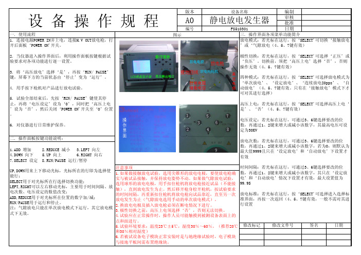
放电次数:若光标在这行,可通过3、6键选择要改的位 数,再通过1、2键来增大或减小该数字,若为0,则默认为 最大值9999且只在‘设定放电’和‘自动放电’下设置才 有效
UP,DOWN用来上下移动光标,光标所在的行即为选择使 能行; SELECT用于对光标所在行选择切换功能; LEFT,RIGHT可以左右移动光标,主要用于时间间隔、放 电次数、电压设定的数值改变; ADD,REDUCE用于对光标所在位置的数字加/减; RUN/PAUSE用于运行和停止。 注:气隙放电只能在单次放电模式下运行,其它放电模 式下无效。
6. 对仪器进行日常维护保养。
极性切换:若光标在这行,按‘SELECT'可选择‘正压’或 ‘负压’。切换前,须把‘高压上电’选择‘否’,否则 操作无效(4、5、7键有效)
四种模式:若光标在这行,按‘SELECT'可选择放电模式为 ‘单次放电’、‘设定放电’、‘连续放电20pps’、‘自 动放电’(4、5、7键有效。只有在‘接触放电’模式下才 可对其进行选择)
设备操作规程
一. 使用流程 1. 连接电源POWER IN并上电,连接H.V OUT放电枪,打 开后面板‘POWER ON'开关。
版本
A0
编号 图示
设备名称
编制静电放电发生器审核 批准FS510301
日期
三. 操作界面各项菜单功能简介
放电模式:若光标在这行,按‘SELECT'可切换‘接触放电
’或‘气隙放电(4、5、7键有效)
注意事项 1.如果做接触放电试验,选用尖锥形的放电电极,要使放电枪确 实与被试品接触,并保持放电姿势不动。如果做气隙放电试验, 选用球形的放电电极,用手扣住枪机将放电枪接近试品(不能接 触),直到放电发生为止。然后移开枪身松开枪机,按试验要求 的时间间隔,再重新扣住枪机将放电枪向试品靠近,直至另一次 放电发生为止(气隙放电选用手动的单次放电模式)。 2.换放电电极及插入放电枪必须在断电情况下进行。 3.极性切换之前,高压上电须选择‘否’,否则无法切换。 4.试验应在正常操作时,操作人员可能触摸到被测设备表面上的
- 1、下载文档前请自行甄别文档内容的完整性,平台不提供额外的编辑、内容补充、找答案等附加服务。
- 2、"仅部分预览"的文档,不可在线预览部分如存在完整性等问题,可反馈申请退款(可完整预览的文档不适用该条件!)。
- 3、如文档侵犯您的权益,请联系客服反馈,我们会尽快为您处理(人工客服工作时间:9:00-18:30)。
elex静电发生器操作手册
使用说明:
1、试验过程中,屏上有闪烁的高压符号显示,时刻提醒操作人员注意安全;
2试验结果显示功能,可自动判断试验结果(试验通过或试验失败),并能可靠记录试品过电流、闪洛或击穿时的电压;
3、试验结果声音报警功能,试验通过或试验失败时,设备会发出不同的报警声音,试验人员可直接由报警声音辨认试验的结果;
4、暂停功能,自动控制时,此功能可做到在任意点实现升压或降压的暂停,暂停时间可由试验人员灵活掌握,方便观察试品状态
5、自动计时功能,自动控制时,当电压自动上升至设定值时,设备自动开始计时,当计时时间到,显示试验结果,设备自动回到零
6、手动计时功能,手动控制时,计时器可手动启动,当耐压时间到,设备自动回到零位(仅台式设备有此功能);
7、手动控制模式,此模式类似于传统的电动升/降压方式,上升/下降由按钮控制,设备自动判断上/下限位,有过电压保护;
8、升压速度智能控制,当电压达到目标电压80%时,升压速度会自动减慢,当达到目标电压90%时,升压速度进一步减慢。