高压静电发生器外文翻译、中英文翻译、外文文献翻译
A 10 kW high-voltage pulse generator

I. INTRODUCTION
Worldwide research and development on corona plasma techniques for pollution control and sustainable development are gradually leading to industrial applications. Investigations range from odor treatment, indoor air cleaning, volatile organic compound ͑VOCs͒ abatement, and flue gas cleaning to CO2 conversion and biogas cleaning.1–3 To successfully promote these industrial applications, the availability of highly efficient and reliable high-voltage-pulsed power sources is critical. In previous work,2,4 we have reported that by using various voltage pulses and/or corona reactors pulsed streamer coronas may develop into two phases, corresponding to primary and secondary streamers. Energy transfer during these two phases depends on the voltage rise rate and the pulse duration. Optimized relationships among the voltage rise time, the peak voltage, the pulse duration, the size of corona reactor, the output impedance of the highvoltage pulse generator, the stray capacitance of the corona reactor, and the corona energy transfer per unit length of reactor are also discussed.3–5 Most critical elements of the corona-induced plasma system, such as high-voltage switching, transmission line transformer, electrical diagnostics, and costs of the voltage pulse generator are discussed in separate papers.6,7 A general principle for designing a corona plasma system has been proposed in order to improve the initial radical production and to increase the total energy transfer efficiency.7 According to the proposed design principle, in this article we discuss a 10 kW repetitive high-voltage pulse generator. The ultimate objective of this work is to develop an industrial corona-induced plasma system with an average power of 50–100 kW. Characteristics of corona plasma in a wire-plate reactor, the triggered spark-gap switching, and the spark-gap lifetime evaluation will be reported in separate papers.
蒸汽发生器水位控制中英文对照外文翻译文献

中英文资料外文翻译文献Research on Fuzzy Control for Steam Generator Water LevelI. INTRODUCTIONThe steam generator is one of the main devices in PWR nuclear power plant, in order to ensure the safety of nuclear power plant during operation; the steam generator‟s water level must be controlled in a certain range. When the nuclear power plant is running, as the steam flow or the water flow changing, the amount of boiling bubbles in the steam generator will change due to local pressure or temperature change, the instantaneous water level showed “false water level” phenomenon .The existence of “false water level” made it difficult to control the water level. The introduction of feed-forward control to the traditional single-loop PID control can, in a certain extent, overcome the "false water level" phenomenon. But the conventional PID control method in the process of steam generator water level control has some shortcomings. To the steam generator that has highly complex, large time-delay and nonlinear time-varying characteristics, the PID parameters tuning is a tedious job and the control effect is very poor. Furthermore, to achieve good control performance still as conditions changing, it often needs to change the PID controller parameters. But the analog PID controller parameters are difficult to regulate online. Fuzzy control is a kind of nonlinear control strategy based on fuzzy reasoning, which express operating experience of skilled manipulation men and common sense rules of inference through vague language. Fuzzy control do not need to know precise mathematical model of controlled object, is not sensitive to the change of process parameters, is highly robust and can overcome non-linear factors, so, fuzzy control has faster response and smaller ultra- tone, can get better control effect. Based on understanding above, this paper design a steam generator water level fuzzy controller, the simulation shows that thecontroller has good control performance and practical value.II. DYNAMIC CHARACTERISTICS OF STEAM GENERATORThe transfer function of PWR steam generator‟s mathematical model of the general form shows below:y(s)=GW(s)QW(s)+GS(s)QS(s) (1)where y is the steam generator water level; QW for the water flow; QS for the steam flow; GW (s) for the impact of the water flow to the steam generator water level; GS (s) for the effect of the steam flow (load) to the steam generator water level.The balance of the steam generator water level is maintained through the match between the water flow and steam flow. The process that water level changes with the steam flow or water flow changing can be regarded as a simple integration process, but impact of the water flow and steam flow …s change on water level is different.A. Dynamics Characteristics under Water Flow DisturbanceSuppose steam flow GS remains unchanged, and water flow GW step increases, on the one hand because the temperature of feed water is much lower than the temperature of saturated water in the steam generator, so that , when feed water entering, it will absorb a lot of extra heat, the vapor phase bubble contents will reduce, resulting in water level decreasing; on the other hand, the increase in water flow GW made it greater than steam load, and cause water level increases linearly. Comprehensive two factors, after the step increase of the water flow, the water level rise has a time delay process, showing a down then up.B. Dynamic Characteristics under Steam Load DisturbanceSuppose feed water flow GW remains unchanged, and steam load GS step increases, on the one hand the water level will flow down because the steam flow rate is greater than the water flow rate. On the other hand, as the steam load increased, vapor pressure is reduced; the bubble volume on the liquid surface increases, causing the water level increased. Comprehensive two factors, after the step increase of the steam flow rate, the water level down has a time delay process, showing a up then down.The impact on the water level of water flow or steam flow stepping decreased has similar principle as above.As analysis can be seen as above, when the water flow or steam load change, the water level did not follow the change immediately, but there is an opposite process at first. This phenomenon is called "false water level" phenomenon.III. DESIGN OF W ATER LEVEL FUZZY CONTROLLERThe conventional PID controller has a poor control performance to the steam generator that exist“false water level” characteristics, showing a greater overshoot in the tracking time. But a well-designed fuzzy controller is able to overcome the "false water level" phenomenon, and has good control performance.A. Sstructure of Fuzzy ControllerThe structure showed in Figure 1.Figure 1. Structure of steam generator water level fuzzy controllerChoose the water level error (e) and change rate of error (ec) as input of the fuzzy controller, the output of the fuzzy controller is the added value of the valve opening signal Δu. Meanwhile, use the steam flow feed-forward to overcome the "false water level" phenomenon, use water flow feedback to overcome fluctuations in water supply side . k1, k2 were water flow and steam flow transmitter conversion factor. To ensure the water flow to match the steam flow, k1 and k2 values should be equal to.B. Fuzzy theory, fuzzy subset and Membership FunctionThe fuzzy Analects of e, ec and u are [-6, 6], both with seven fuzzy sets NB (negative big), NM (negative middle), NS (negative small), ZO (zero), PS (positive small), PM (positive middle) and PB (positive big) to describe. e, ec and, Δu are all using triangular membership function (see Figure 2).Figure 2. Input and output variable membership functionC. Fuzzy control rule tableThe establishment principle of fuzzy control rules are: when the error is large, the output control volume should give priority to eliminate error as soon as possible; when the error is small, the output control volume should givepriority to prevent overshoot. Where ec is negative ,it shows that water level has a rising trend, if the water level is high at this time, then we should reduce the valve opening signal; whereas, we should open the valve more. Through a comprehensive analysis of expertise, the establishment of rule table shown in Table 1.Table 1. Fuzzy control rule tableD. Fuzzy Reasoning and SolutionThis fuzzy inference system uses Mamdani. The basic properties of fuzzy inference system set to: "and" operation with a very small operation; "or" operation uses the maximum operation. Using a very small operation fuzzy implication, fuzzy rules integrated with great operations center Defuzzification method used. IV . SIMULATION EXAMPLESA pressurized water reactor steam generator in Chinese Qinshan nuclear power station has empirical model G1 (s), G2 (s) below:()()()()⎪⎪⎩⎪⎪⎨⎧+⋅++++==---7%15,)128(415.0)13)(129(19.36%90,)13)(129(19.3)()(551Ps s s s s e Ps s s s e e s G s G s ssp τ()()8%90,14398.0)124(819.3)(2Ps s s s s e s G +++--=where Ps denote the rated load. When load at 15% ~ 90% Ps, use (6) and (8); when load less than 15% Ps, use (7) and (8).Figure 3. Expected water level step response diagramThe coefficients in Control system are k1=k2=0.5. Water control valve is a king of linear valve, its gain is 4. The quantitative coefficients of e and ec are 6 and 60 respectively; the scale factor of u is 0.5. We limit water flow the range of 0 kg / s to the rated flow 258kg / s when simulation. Consider the expected level step from the initial 0m to 10m, water level response is shown use the solid line in Figure 3. For contrasting the increase effect of fuzzy controller, we also carried out using the traditional PID control simulation. We can see, compared with traditional PID control, fuzzy controller has reported significant improvements in overshoot, settling time, steady degrees.V. CONCLUSIONThis paper designed a water level fuzzy control system aimed at steam generator…s characteristics of large time delay and model uncertainty. We also gave a simulation to the steam generator of Qinshan nuclear power plant, and achieved satisfactory results. The method can also be used for other large time -delay and time-varying process control model, and has broad application prospects.蒸汽发生器水位模糊控制研究1.导论蒸汽发生器是压水反应堆式核电厂里的一个重要的设备。
英文版直流高压发生器说明书

User manual book--High V oltage DC GeneratorWarningPeople who use of this product must have a "high-voltage test certificate".Please read the 168 regulation of "electric power regulatory" when you use this product,and install two apparently disconnected point between power and the tester, when replacing the tester or Connecting line, you should break the two disconnect point of power supply.Check tester control box, the high-voltage cylinder and the grounding wire is connected together before testing. The grounding wire should be connected rightly to the earth.The large capacitor loader must discharged through the resistor of 100Ω/ V. Don’t contact the rod resistor with the loader immediately, you should put the rod resistor close to the sample gradually, keep a certain distance, and then discharge with hiss. When there is no sound, we can use rod resistor finally discharge by connecting to earth.If the loader is a capacitive loader, before test you must connect with resistor.When the voltage is more than 200kV, although the test personnel wear insulated shoes and at a safe distance from the outside area, but because of the effects of high voltage DC ion distribution of space electric field, it can lead to different DC potential of standing people nearby. Don’t handshake each other or touch any grounding body, otherwise there will be a mild electric shock phenomenon, this phenomenon happens in dry areas and winter commonly, but it generates little energy, so it can do no harm to people.After finishing the test, you must connect the grounding wire to the end of high voltage output, and then you can remove the lead wire off.CATALOGIntroduction (4)Principle of operation (4)Technical parameter (4)Function (7)Operation steps (9)Fault resolve (13)Product complete sets (13)Quality assurance (14)Service Promise (14)Introduction The high voltage DC generator is a new product designed according to the new China electric power industry standard DL / T848.1-2004 "DC high voltage generator general technical conditions". This product is mainly used for DC endure experiment to high voltage device such as Electric Power Cooperation, Metallurgy, Iron and Steel enterprises.Principle of operationAC 220outTechnical parameter1. Technical character● The control box is used of aluminum alloy structure.● It uses the new technology such as PWM pulse-wide modulation, middlefrequency high voltage and high power IGBT device.● It uses voltage feedback; output stability is less than 3%.● Full range of voltage output, voltage regulating accuracy is less than 1%, thestability of voltage error is less than 1.5%, the voltage error ± (1.5% ±2 words), the current error ± (1.5% ± 2 words).●Raise voltage from zero voltage potentiometer.●The 0.75UDC/1mA function button is convenient for zinc oxide arrester test, andthe accuracy is ±(3%±2words).●Over voltage protection uses dialing number set, and the error is ±1%.●High voltage cylinder is used of new materials, lightweight and sturdy. It’s co atedwith special insulating materials, electrical performance and moisture-proof ability is good.●The product conforms to DL / T848.1-2004 technology requirements, and passedthe center test of electrical equipment quality inspection, strictly according to the enterprise standard.2. Technical parametersNote: As the product update, we don’t notice any more, according to the sample, the company reserves the right of interpretation.Function(1)Control box Panel1、Ground terminal: When testing, the grounding terminal of control box and high-voltage cylinder should be connected together, and then connected with the earth. 2、Output port is used for the connection of the control box and high-voltagecylinder . We only rotate the cable pressing plug clockwise in place when connecting, only rotate the cable plug anti-clockwise when broking.3、V oltage setting switch: Used for setting the over-voltage protection value. Thedisplay unit of dial switch is kV, set values is 1.1 times of the test voltage.4、Power input socket: A random configuration of power line and the power inputsocket. (AC voltage 220V±10%, socket with fuse.)5、Digital voltage meter: Digital display high voltage DC output voltage.6、Digital current meter: Digital display high voltage DC output current.7、Power switch: Forward press, the power is on, the red lights, conversely toshutdown.8、Yellow light button: This function is designed for zinc oxide arrester formeasurement of 0.75UDc1mA. It’s effective when the green lights. After pressing the button, output voltage reduce to the original 0.75%, and keeps this state. Press the red button, red light and green light all out, high pressure cuts off and exits0.75 times state.9、The green button: High-voltage output button, high voltage indicator lamps. In redlight state, press the green button, the green light and red light out, this means high voltage circuit is switched on, then we can raise voltage. It’s Effective that thisbutton must be on voltage regulating potentiometer zero state. If press the green button, the green light is bright red, at the same time the red light is brighter, but release the green button, green light out and red light, it means Internal protection circuit has been working.10、Red button: the red light shows that the power is switched on and the high voltageis cut off .In the green state ,press the red button, red light is bright, high voltage is cut off.11、V oltage adjusting potentiometer: The potentiometer is a multi-turn potentiometer.Rotate clockwise to boost, and conversely to Step-down. The potentiometer has the function of controlling electronic zero protection, so must firstly return to zerobefore boosting.(2)High-voltage cylinder1、High voltage terminals (connect Microampere meter and water resistance orcurrent-limiting resistor)2、Equipotential shielding for HV3、High-voltage cylinder4、Grounding terminal5、Intermediate frequency output terminal6、Base(3)Testing connectionOperation steps(If capacitive load, should access the current-limiting resistor)1、 Check integrity before using the tester, make sure that there is no circuit breakeror short circuit in connecting cable, and equipment without rupture damage.2、Put the control box and High-voltage cylinder in place, then respectively connectpower line, control cable and grounding line ,protect all grounding wire separatelyconnecting to the sample point (one point tie to the earth ).Forbids the groundingwire connected in series. For this purpose, you should use the DHV specialgrounding wire.3、Keep power switch off and check voltage potentiometer at zero. Over voltageprotection setting value is generally 1.1 times of the testing voltage.4、No load ,step-up to verify the sensitivity of over voltage protection setting.5、Put power on, the red light, it means power on.6、Press the green button, then the green light, it means high voltage is outputting7、Regulate pressure regulating potentiometer clockwise direction smoothly, outputend is raised from zero to a desired voltage, according to the prescribed timerecording current meter readings, and check the control box and high voltageoutput line has no abnormal phenomenon or sound.8、 Reduce voltage ,regulate pressure regulating potentiometer to zero, then press )the red button, cut off the high voltage and then turn the power switch off.9、To test for leakage and DC voltage endurance, check test confirmation testerwithout exception, you can start test for leakage and DC voltage endurance test.Connect the test items and grounding wire, and then can open power s before thereis no mistake.10、Raise to the required voltage or current. The suitable raising speed is 3 - 5kV testvoltage per second. For large capacitance, we need to monitor of ammetercharging current not exceed the maximum charging current tester while raisingvoltage. For small capacitive products such as zinc oxide arrester, lightningarrester, we firstly raise to a desired voltage (current) at 95%, then slowly raiseto a desired voltage (current).From the digital display meter, we can read outvoltage (current) value. For zinc oxide arrester 0.75UDC - 1mA measurement, we firstly rise to UDC1mA voltage value, and then press the yellow button, when the voltage is reduced to the original 75%, and remains in this state. At this time, current value can be read. After the measurement, regulate pressure regulating potentiometer anticlockwise to zero, press the green button. Press green button.When you need raising voltage againYou can use external High Voltmeter to measure the output voltage if necessary.11、Reduce voltage and turn off the power after finish testing.12、Several methods for measuringa. Normal, when the wires are connected, suspend wires of tester, rising to thetesting voltage with no load ,Read stray current I’first, and then try to read the total currentⅠ1 with load, sample leakage current: Io =Ⅰ1—I’b.When we need an accurate measurement of sample leakage current, we should connect the high voltage micro ammeter to the high side (see below).Microampere meter must have a metal shielding; shielding line should be connected with test. The shielding of High voltage lead should be closely connected with end shielding. If the sample surface is dirty, we should exclude effect of samplesurface leakage current. In samples of high potential end, several times around with bare metal cords (see below).c.For sample such as zinc oxide, magnetic blow-out arrester, the grounding end can be breaked up; also can measure by connecting ammeter to the bottom (ground potential side) of test items. when we exclude effect of sample surface leakage current,we can use soft of bare copper wire in the sample to end the last laps around the shield ,and connect shielding line (see below)13、For small capacitive products ,such as zinc oxide and lightning arrester ,itdischarges quickly through pressure resistance. For large capacitive products such as cable, while test voltage self discharging to the test voltage is below 20%, then it can discharge by supporting the discharging rod. Keep connect the grounding wire to the capacitive products before voltage discharging completely, and then we can remove high voltage lead and other wire.14、If green light is off, red light is bright, voltage is dropping, which is relatedprotection to the product .You should turn off the power switch, panel lights are not bright. Turn the pressure regulating potentiometer to zero position, while low voltage capacitor discharging completely, then open the power switch a minute later. If you start a no loading test again, you can begin raising voltage test before checking all situations.Fault resolveComplete sets of products1. Control box 12. High-voltage cylinder 13. Use’s manual book 14. Fuse some5. Power cable 16. Special grounding wire 17. Discharging rod 18. Water resistance or current limiting resistor 19. Microampere ammeter 1Quality assurance1. The equipment made by the company can meet the requirements of the buyer, andprovide free pre-sale technical services.2. Products of the company have effective inspection and control, strictly productaccording to ISO9001 quality system of production service.3. The quality of our products is according to the standards of our company andrelevant national standards.Service PromiseThe product’s warrant time is one year, the implementation of "Three Guarantees", life-long repairing, all of the equipment of the company quality problem, we can provide free repair in the warranty period. Improper operation due to the user or accidental damage, we can provide preferential services. We’ll be looking forward to your valuable opinions to our products.。
电子类文献中英文翻译发电机
电子类文献中英文翻译发电机Electricity is the backbone of modern society, and it is generated by using various methods, with one of the most common ways being through the use of generators. This article explores the concept of generators and their role in electricity production.GeneratorA generator is a device that transforms mechanical energy into electrical energy. It works on the principle of electromagnetic induction, which was discovered by Michael Faraday in the early 19th century. A generator consists of two parts: the rotor and the stator. The rotor is the rotating part of the generator, while the stator is the stationary part. The two parts are separated by an air gap.When the rotor rotates inside the stator, it produces a magnetic field that cuts across the wires in the stator. This creates an electric current. The amount of electric current generated by the generator depends on the speed of the rotor and the number of wire turns in the stator.Types of GeneratorsThere are two main types of generators: AC generators and DC generators. AC generators generate alternating current, while DC generators generate direct current.AC GeneratorsAC generators are the most common type of generators used in modern society. They produce electrical power by rotating a coil of wire around a magnetic field. This creates a changing magnetic field, which induces a current in the coil. The current flows back and forth at a set frequency, resulting in an alternating current.The advantage of AC generators is that the voltage and frequency can be easily controlled. This makes it possible to build large power plants that can produce electricity at high voltage and transmit it over long distances.DC GeneratorsDC generators are less common than AC generators, but they are still used in some applications. They generate a constant DC voltage by rotating a coil of wire around a magnetic field. The voltage produced by a DC generator is proportional to the speed of the rotor and the number of wire turns in the coil.The main disadvantage of DC generators is that the voltage cannot be easily changed. This makes them unsuitable for large power plants and long-distance transmission.ConclusionGenerators play a vital role in the production of electricity, and the development of more efficient and effective generators has greatly improved the quality of life for people all over the world. The ability to generate electricity has enabled people to access a wide range of electronic devices that improve communication, enable faster transportation, and enhance safety and security. As technology continues to advance, the generators of the future will undoubtedly become even more efficient and effective, providing sustainable, reliable, and affordable energy for generations to come.。
南韩GXR高压发生器说明书KV与mA校准部分中文
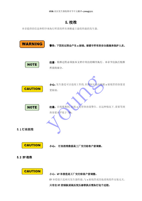
5.校准
本章提供的信息和程序来执行所需的所有调整建立最优性能的发生器。
警告:下面的过程会产生 x 射线。请遵守所有的安全措施来保护人员。
5.1 灯丝校准
注意:校准过程必须按本文档中列出的顺序执行。本章节仅执行校准 所需的部分。
小心:发生器是可以连续工作的,但期间安装应根据 x 射线管的容量设 置限制。
‘*’星号标志将会消失。在这个阶段,HT 控制板自动计算其他千伏设置值。
9. 千伏校准完成。
检查其他千伏的千伏峰值测量步骤,改变千伏值通过使用千伏向上/向下按钮(
),
重复步骤 2 到步骤 3。千伏校准,向上/向下改变 10 补偿值将导致 1 kV 的变化。
young
GXR 高压发生器校准章节中文翻译--youngyyzz
n 消息
TEST
u PASSED yo OK
描述
为具体的校准步骤表明初次校准。校准步骤:在处 理 校准过程之前通过了要求:如果第一次安装发生 器,或移动到不同的位置,或 x 射线输出不是设定 值后,然后忽略该消息并执行新的校准。 表明校准后的反馈值在误差范围内:继续下一步 校准
ABNORMAL
表明校准后的反馈值超过误差范围:改变偏移值, 重复当前的校准步骤
如果补偿值被修改在现场校准,这不同于工厂设置补偿值,然后星号(*)将添加在补偿值后面。如果修
改后的设置用于 x 射线曝光,然后将它保存为新的设置和星号(*)的迹象将会消失。
执行校准过程从低 kV、mA 开始。参考附录 c·mA 校准档位表所示。
g 在屏幕的右侧, 显示关于 mA 校准的状态消息。如下表消息描述所示。
GXR 高压发生器校准章节中文翻译--youngyyzz
工业类英语词汇_21
器electo-hydraulic servocontrolled fatigue testing machine,电液伺服疲劳试验机electro-optical distance meter,光电测距仪electroacoustic transducer,电声换能器electroacoustical reciprocity theorem,电声互易定理electrochemical analysis,electrochemical analyzer,电化学式分析器electrochemical transducer[sensor],电化学式传感器electrode,电极electrode potential,电极电位electrode signal,电极信号electrode type salinometer,电极式盐度计electrode with a mobile carrier,流动载体电极electrodeless-discharge lamp,无极放电灯electrodialysis method for desalination,电渗析淡化法electrodynamic instrument,电动系仪表electrodynamic meter,电动系电度表electrodynamic vibrator,电动振动器electroence-phalographic transducer[sensor],EEG传感器electrogravimetric analysis,electrohydraulic control,电液执行机构electrohydraulic control,电液伺服阀electrolysis humidity transducer[sensor],电解式湿度传感器electrolytic cell,电解池electrolytic hygrometer,电解湿度计electromagnet,电磁铁electromagnet damping galvanometer,电磁阻尼振动子electromagnet fluid damping galvanometer,电磁液体阻尼振动子electromagnetic brake,电磁制动器electromagnetic braking,电磁制动electromagnetic counter,电磁计数器electromagnetic current meter,电磁海流计electromagnetic damper,电磁阻尼器electromagnetic deflector alignment system,电磁偏转对中系统electromagnetic distance meter,电磁波测距仪electromagnetic element,电磁元件electromagnetic flowmeter,电磁流量计electromagnetic gun,电磁枪electromagnetic induction,电磁感应electromagnetic interference,电磁感应法仪器electromagnetic imterference,电磁干扰electromagnetic lens,电磁透镜electromagnetic method instrument,电磁法仪器electromagnetic methods,电磁法electromagnetic radiation,电磁辐射electromagnetic screen,电磁屏蔽electromagnetic transducer[sensor],电磁式传感器electromagnetic unit,电磁单元electromagnetic vibrator,电磁振动器electromagnetic wave propagation logging instrument,电磁波传播测井仪electrometer,静电表electromotive force(EMF),electromyogrphic transducer[sensor],EMGelectron beam exposure apparatus,电子束曝光机electron beam processing machine,电子束加工机electron capture detector(ECD),电子捕获检测器electron channelling pattern,电子通道花样electron diffraction image,电子衍射象electron diffractometer,电子衍射谱仪electron energy lose spectroscopy(EELS),电子能量损失谱法electron gun,电子枪electron gun alignment adjustment,电子枪对中调节装置electron image intensifier,电子象增强器electron impact desorption(EID),电子轰击解吸electron impact ion source;EI source,电子轰击离子源electron induced desorption(EID),电子诱导解吸electron lens,电子透镜electron microscope,电子显微镜electron mobility detector,电子适移率检测器electron noise,电子噪声electron lperation desk of EPMA,电子探针的电子操纵台electron optical system of EPMA,电子探针的电子光学系统electron optics,电子光学electron paramagnetic resonance spectroscopy;EPR spectroscopy,电子顺磁共振波谱法electron probe,电子探针electron probe micro-analysis(EPMA)电子探针微分析electron probe X-ray microanalyzer,电子探针X射线微区分析仪electron spectrometer,电子能谱仪electron type rock ore densimeter,电子式岩矿密度仪electron wave length,电子波长electron-beam atomizer,电子束原子化器electron-diffraction method(EED),电子衍射法electron-energy analyzer,电子能量分析器electron-hole pairs,电子—空穴对electronic analogue-to-digital converter,电子模/数转[变]换器electronic automatic compensator,电子自动补偿仪electronic balance,电子天平electronic batching scale,电子配料秤electronic bathythermograph(EBT),电子深温计electronic belt conveyor scale,电子皮带秤electronic counting scale,电子计数秤electronic distance-meter theodolite,电子测距光学经纬仪electronic fluxmeter,电子磁通表electronic hoist[hanging] scale,电子吊秤electroinc hoist scale,电子料斗秤electronic integrating fluxmeter,电子积分式磁通表electronic level,电子水准仪electronic measuring instrument,电子测量仪器仪表electronic plane table equipment,电子平板仪electronic platform scale,电子平台秤electronic railway scale,电子轨道衡electronic sampling switch,电子采样开关electronic tacheometer,电子速测仪electronic tesing machine,电子式试验机。
高压静电场发生器
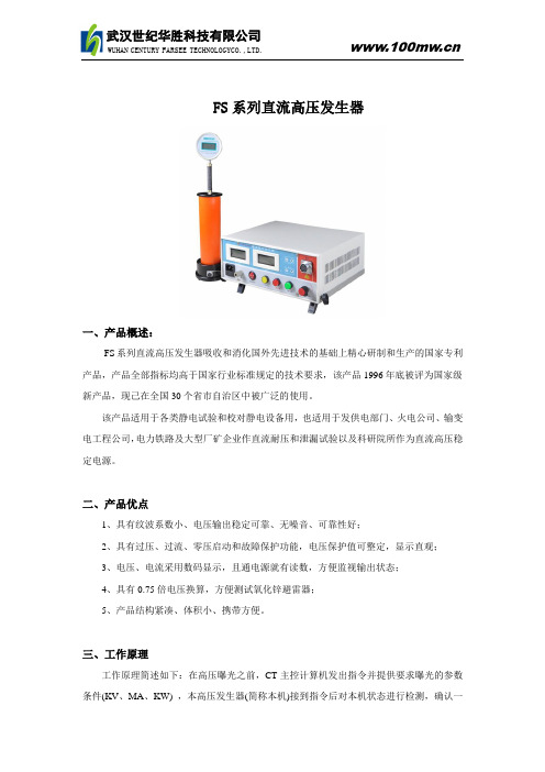
FS系列直流高压发生器
一、产品概述:
FS系列直流高压发生器吸收和消化国外先进技术的基础上精心研制和生产的国家专利产品,产品全部指标均高于国家行业标准规定的技术要求,该产品1996年底被评为国家级新产品,现己在全国30个省市自治区中被广泛的使用。
该产品适用于各类静电试验和校对静电设备用,也适用于发供电部门、火电公司、输变电工程公司,电力铁路及大型厂矿企业作直流耐压和泄漏试验以及科研院所作为直流高压稳定电源。
二、产品优点
1、具有纹波系数小、电压输出稳定可靠、无噪音、可靠性好;
2、具有过压、过流、零压启动和故障保护功能,电压保护值可整定,显示直观;
3、电压、电流采用数码显示,且通电源就有读数,方便监视输出状态;
4、具有0.75倍电压换算,方便测试氧化锌避雷器;
5、产品结构紧凑、体积小、携带方便。
三、工作原理
工作原理简述如下:在高压曝光之前,CT主控计算机发出指令并提供要求曝光的参数条件(KV、MA、KW) ,本高压发生器(简称本机)接到指令后对本机状态进行检测,确认一
切正常后发出高压准备好的信息给CT主机,本高压发生器(简称本机)接到指令后对本机状态进行检测,确认一切正常后发出高压准备好的信息给CT,随后CT主机下达曝光命令并传送曝光控制脉冲到本机,本机启动旋转阳极,激励灯丝电流,主机调整高压变压器初级电压达到CT要求参数值后,送出高压发生器OK信息并开始产生高压供给球管曝光,在整个曝光期间,不断根据管电流的变化,及时调整高压初级电压以保证整个曝光过程产生平稳的脉冲高压和较为恒定的管电流,一旦检测到高压参数异常,立即切断并报出错误代码。
四、技术指标。
高电压绝缘技术相关英文词汇
整理的高电压绝缘技术相关英文词汇Ambient air temperature 周围空气温度External insulation 外绝缘Internal insulation 内绝缘Self-restoring insulation 自恢复绝缘Non-self restoring insulation 非自恢复绝缘Disruptive discharge 破坏性放电Sulfur hexafluoride circuit breaker SF6断路器Rated value 额定值Applied voltage 外施电压Clearance 间距两个导电部件间的、沿这些导电部件间最短路径的直线距离Insulation level 绝缘水平Power frequency withstand voltage 工频耐受电压Impulse withstand voltage冲击耐受电压Switching impulse 操作冲击Lightning impulse withstand voltage(LIWV)雷电冲击Atmospheric conditions 大气条件Altitude correction 海拔修正Long air-gap 长空气间隙Correction coefficient 校正系数Plateau region of china 中国高原地区Relative atmospheric density 相对大气密度Absolute humidity 绝对湿度Triangulation 三角测量Transducer 转换器;变频器;换能器,转换装置;发送器;传感器Time delay histogramWave front time 波前时间Wave tail time 波尾时间Impulse generator (IG) 冲击电压发生器Marx’s circuit 马克斯回路Trigger gap 点火间隙Testing transformer 试验变压器Power transformer 电力变压器Cascade connection (变压器的)串级连接Cockcroft-Wolton电路(直流)串级整流电路Accreditation system 认证制度Sphere gap 球间隙Rod gap 棒间隙Ultra high voltage (UHV)特高压Extra high voltage (EHV)超高压Electric charge 电荷Electric field 电场Electric potential 电位Poission’s equation 泊松方程Permittivity in vacuum 真空中的介电常数Laplace’s equation 拉普拉斯方程Conformal mapping method 保角变换法Electric flux density 电通量密度Absolute dielectric constant 绝对介电常数Relative dielectric constant 相对介电常数Conductivity 电导率Current density 电流密度Difference method 差分法Taylor expansion 泰勒展开式Finite elements method 有限元法Charger superposition method 模拟电荷法Corona noise 电晕干扰Corona discharge 电晕放电Electric shock 电击Insulating material 绝缘体Dielectric 电介质Insulating property绝缘性质Dielectric breakdown 绝缘击穿Dielectric strength 介质强度Dielectric polarization 介质极化Polarized charge 极化电荷Bound charge 束缚电荷Dielectric loss 介质损耗Dielectric absorption 介质吸收Spontaneous charging current 瞬时充电电流Absorption current 吸收电流Leakage current 泄流电流Ionization 电离Diffusion and recombination (分子)扩散和复合Impact ionization 碰撞电离Electron avalanche电子雪崩First ionization coefficient 第1电离系数Criterion for spark discharge 汤逊火花放电条件Secondary ionization coefficient 第2电离系数Streamer theory 流注理论Plasma 等离子体Leader (放电)先导Main stroke 主放电Glow discharge 辉光放电Arc discharge 电弧放电Intrinsic breakdown 本征击穿Electronic thermal breakdown 电子热击穿Electronic avalanche breakdown场致发射击穿Partial discharge degradation 局部放电劣化Treeing degradation 树枝化劣化Electric tree 电树枝Water tree 水树枝Chemical tree 化学树枝Composite insulation 复合绝缘Surface discharge 沿面放电Insulation characteristics test 绝缘特性试验High voltage direct current test 直流高压试验Dielectric loss tangent test 介质损耗角正切试验Alternating current test 交流电流试验Type test型式试验Acceptance test 验收试验Test after installation 竣工试验Step by step voltage rising 逐步升压法Residual life 剩余寿命Schering bridge 西林电桥Acoustic emission sensor (AE)传感器Corss-linked polyethylene insulated polyvingl-chrolide sheathed cable 交联聚乙烯Ceramic varistor 陶瓷变阻元件Long wave frontsThe external insulation under high-altitude, icing, pollution and other adverse natural conditions need in-depth test studies.Semi-peak value resistance 半电压电阻Rationalization of insulation 绝缘配合gantry crane 龙门吊车航吊empirical 经验的,实验的empirical analysis / assumption / coefficient / comparison / constant经验分析/假设/系数/比较/常数smoothing capacitor 平波电抗器valve tower 分水塔loose flange 活套法兰mounting hole 安装孔o ring groove o 型坡口长间隙击穿long air gap,breakbown ofAuxiliary equipment 辅助设备Long term energisation at 855kV 在855kV下长期运行Water repellant properties of composite insulator负荷绝缘子的憎水性Resonant Test System 谐振试验系统Leader Propagation Model 先导发展模型Dielectric loss 介质损耗Series resonant 串联谐振Stochastic 随机性Oil impregnated paper bushing(OIP)油浸纸套管Epoxy resin impregnated bushing 环氧浸纸套管PASS (Plug and Switch System)Condenser 电容器Resin Impregnated Paper bushing(RIP) 树脂浸纸套管Bushings 套管Wall bushings 穿墙套管Routine and special tests 常规和特殊试验Power/dissipation factor 介质损耗因数chopped lightning impulse 雷电截波permanently hydrophilic insulator 憎水绝缘子artificial climate hall 人工气候室composite housed SF6 filled bushing SF6气体绝缘复合套管creeping distance 爬电距离(绝缘子的)Corrugate pipe 波纹管ultra-high frequency measurement 超高频法(测局放的一种方法)Capacitive voltage dividing principle 电容分压原理Electrolyte 电解液Bode diagram 波特图Environment humidity 环境湿度Non linearity characteristics 非线性特性Pollution duration 污秽持续时间(污秽试验中)Resonance potential 共振电压Glow discharge 辉光放电Electric arc discharge 电弧放电Dielectric breakdown discharge 电击穿强度Sparking voltage 火花电压Formation 老练处理Polarity effect 极性效应Edge effect 边缘效应Coaxial cylinder gap 同轴圆筒间隙Knife edge electrode 刃型电极Virtual front time 视在波前时间Virtual time to half value 视在波尾时间Peak value 峰值Time above 90% 90%持续时间Discharge ratio 放电概率50% flashover voltage 50%放电电压Main stroke 主放电Electronegative gas 电负性气体Lightning rod 避雷针Grounding/ eathling 接地Root mean square value 有效值(方均根值)Distortion factor 波形畸变率Cascade connection 串接(试验变压器)Ripple factor 纹波系数Multistage impulse voltage generator 多级冲击电压发生器Electromagnetic type potential transformer 电磁式电压互感器Capacitance potential device 电容式电压互感器Damped capacitor divider 阻尼电容分压器Scale factor 分压比Matching resistor 匹配电阻Multiple level method 多级法(测量50%放电电压的一种方法)Up and down method 升降法(测量50%放电电压的一种方法)Impulse peak voltmeter 峰值电压表Current measuring shunt 分流器Coaxial tubular shunt 同轴分流器Insulation characteristics test 绝缘特性试验Insulation resistance test 绝缘电阻试验Polarization 极化指数Leakage index 泄漏指数Schering bridge 西林电桥Oscillating impulse voltage OIV 振荡冲击电压波形Oscillating lighting impulse OLI 振荡雷电波Oscillating switching impulse OSI 振荡操作波。
- 1、下载文档前请自行甄别文档内容的完整性,平台不提供额外的编辑、内容补充、找答案等附加服务。
- 2、"仅部分预览"的文档,不可在线预览部分如存在完整性等问题,可反馈申请退款(可完整预览的文档不适用该条件!)。
- 3、如文档侵犯您的权益,请联系客服反馈,我们会尽快为您处理(人工客服工作时间:9:00-18:30)。
High Voltage Power Supplies for Electrostatic ApplicationsCliff Scapellati, Vice President of EngineeringAbstractHigh voltage power supplies are a key component in electrostatic applications. A variety of industrial and scientific applications of high voltage power supplies are presented for the scientist, engineer, specifier and user of electrostatics. Industrial processes, for example, require significant monitoring of operational conditions in order to maximize product output, improve quality, and reduce cost. New advances in power supply technology provide higher levels of monitoring and process control. Scientific experiments can also be influenced by power supply effects. output accuracy, stability, ripple and regulation are discussed.Contributing effects such as output accuracy, stability, ripple and regulation are discussed.I.IntroductionThe use of high voltage in scientific and industrial applications is commonplace. In particular, electrostatics can be utilized for a variety of effects. Broadly stated, electrostatics is the study of effects produced by electrical charges or fields. The applications of electrostatics can be used to generate motion of a material without physical contact, to separate materials down to the elemental level, to combine materials to form a homogeneous mixture and other practical and scientific uses. By definition, the ability of electrostatic effects to do work requires a difference in electrical potential between two or more materials. In most cases, the energy required to force a potential difference is derived from a high voltage source. This high voltage source can be a high voltage power supply. Today's high voltage power supplies are solid state, high frequency designs, which provide performance and control unattainable only a few years ago. Significant improvements in reliability, stability, control, size reductions, cost and safety have been achieved. By being made aware of these improvements, the user of high voltage power supplies for electrostatic applications can benefit. Additionally, unique requirements of high voltage power supplies should be understood as they can affect the equipment, experiments, process or product they are used in.II.Operational Principles of High Voltage Power SuppliesA simplified schematic diagram of a high voltage power supply is shown in Fig.1.The input voltage source may have a wide range of voltage characteristics. AC sources of 50Hz to 400Hz at <24V to 480V are common. DC sources ranging from 5V to 300V can also be found. It is critical for the user to understand the input voltage requirement as this will impact overall system use and design. Regulatory agencies such as Underwriters Laboratory, Canadian Standards Association, IEC and others are highly involved with any circuits connected to the power grid. In addition to powering the main inverter circuits of the power supply, the input voltage source is also used topower auxiliary control circuits and other ancillary power requirements.The input filter stage provides conditioning of the input voltage source. This conditioning is usually in the form of rectification and filtering in ac sources, and additional filtering in dc sources. Overload protection, EMI, EMC and monitoring circuits can also be found. The output of the input filter is typically a dc voltage source. This dc voltage provides the energy source for the inverter. The inverter stage converts the dc source to a high frequency ac signal. Many different inverter topologies exist for power supplies. The high voltage power supply has unique factors which may dictate the best inverter approach. The inverter generates a high frequency ac signal which is stepped up by the HV transformer. The reason for the high frequency generation is to provide high performance operation with reduced size of magnetics and ripple reduction storage capacitors. A problem is created when a transformer with a high step up ratio is coupled to a high frequency inverter. The high step up ratio reflects a parasitic capacitance across the primary of the high voltage transformer. This is reflected as a (Nsec:Npri)2 function. This large parasitic capacitor which appears across the primary of the transformer must be isolated from the inverter switching devices. If not, abnormally high pulse currents will be present in the inverter.Another parameter which is common to high voltage power supplies is a wide range of load operations. Due to the presence of high voltage, insulation breakdown iscommonplace. The inverter robustness and control loop characteristics must account for virtually any combination of open circuit, short circuit and operating load conditions. These concerns as well as reliability and cost, must be addressed in the High V oltage Power Supply Inverter topology.The high frequency output of the inverter is applied to the primary of the high voltage step-up transformer. Proper high voltage transformer design requires extensive theoretical and practical engineering. Understanding of magnetics design must be applied along with material and process controls. Much of the specific expertise involves managing the high number of secondary turns, and the high secondary voltages. Due to these factors, core geometry, insulation methods and winding techniques are quite different than conventional transformer designs. Some areas of concern are: volts/turn ratings of the secondary wire, layer to layer insulating ratings, insulating material dissipation factor, winding geometry as it is concerned with parasitic secondary capacitance and leakage flux, impregnation of insulating varnish to winding layers, corona level and virtually all other conventional concerns such as thermal margins, and overall cost.The high voltage multiplier circuits are responsible for rectification and multiplication of the high voltage transformer secondary voltage. These circuits use high voltage diodes and capacitors in a "charge pump" voltage doubler connection. As with the high voltage transformer, high voltage multiplier design requires specific expertise. In addition to rectification and multiplication, high voltage circuits are used in the filtering of the output voltage, and in the monitoring of voltage and current for control feedback. Output impedance may intentionally be added to protect against discharge currents from the power supply storage capacitors.These high voltage components are typically insulated from ground level to prevent arc over. The insulation materials vary widely, but typical materials are: air, SF6, insulating oil, solid encapsulants (RTV,epoxy,etc.). The insulating material selection and process control may be the most important aspect of a reliable high voltage design.Control circuits keep all of the power stages working together. Circuit complexity can range from one analog I.C. to a large number of I.C.s and even a microprocessor controlling and monitoring all aspects of the high voltage power. However, the basic requirement which every control circuit must meet is to precisely regulate the output voltage and current as load, input power, and commandrequirements dictate. This is best accomplished by a feedback control loop.Fig.2 shows how feedback signals can be used to regulate the output of the power supply. Conventional regulation of voltage and current can be achieved by monitoring the output voltage and current respectively. This is compared to a desired (reference) output signal. The difference (error) between the feedback and reference will cause a change in the inverter control device. This will then result in a change of power delivered to the output circuits.In addition to the voltage and current regulation, other parameters can be precisely regulated. Controlling output power is easily accomplished by an XY = Z function, (VI = W), and comparing it to the desired output power reference. Indeed, any variable found within Ohm's law can be regulated, (resistance, voltage, current and power). In addition, end process parameters can be regulated if they are effected by the high voltage power supply (i.e.coatings,flow rates, etc.).III. High V oltage RegulationThe importance of a regulated source of high voltage and/or constant current is critical to most applications involving electrostatics. Variations in output voltage or current can have direct effects on the end results and, therefore, must be understood as a source of error. In high voltage power supplies, the voltage references that are used to program the desired output can be eliminated as a source of significant error by the use of highly stable voltage reference ICs. Typical specifications of better than 5ppm/C are routine. Similarly, analog ICs (op amps, A/D D/A's, etc.). can be eliminated as a significant source of error by careful selection of the devices.There remains one component, unique to high voltage power supplies, which will be the major source of stability errors: the high voltage feedback divider. As seen in Fig.1, the high voltage feedback divider consists of a resistive divider network.This network will divide the output voltage to a level low enough to be processed by the control circuits.The problem of stability in this network results from the large resistance of the feedback resistors. Values of >100 megOhms are common. (This is to reduce power dissipation in the circuit and reduce the effects of temperature change due to self heating). The large resistance and the high voltage rating requires unique technology specific to high voltage resistors. The unique high voltage resistor must be "paired" with a low value resistor to insure ratio tracking under changes of temperature, voltage, humidity and time.In addition, the high value of resistance in the feedback network means a susceptibility to very low current interference. It can be seen that currents as low as 1 X 10⁻⁹ amps will result in >100ppm errors. Therefore, corona current effects must seriously be considered in the design of the resistor and the resistor feedback network. Also, since much of the resistor technology is based on a ceramic core or substrate, piezoelectric effects must also be considered. It can be demonstrated that vibrating a high voltage power supply during operation will impose a signal, related to the vibration frequency, on the output of the power supply.IV. Auxiliary Functions Involves With the High V oltage Power Supply In many applications of high voltage, additional control functions may be required for the instrument. The power supply designer must be as familiar with the electrostatics application as the end user. By understanding the application, the power supply designer can incorporate important functions to benefit the end process.A typical feature that can be implemented into a high voltage power supply is an "ARC Sense" control. Fig. 3 shows a schematic diagram of an arc sense circuit. Typically, a current sensing device such as a current transformer or resistor is inserted in the "low voltage side" of the high voltage output circuits.Typically, the arc currents are equal to: I = (E/R)————————————(1) where I = Arc current in amperes.E = V oltage present at high voltage capacitor.R = Output limiting resistor in ohms.The arc current is usually much greater than the normal dc current rating of the power supply. This is due to keeping the limiting resistance to a minimum, and thereby the power dissipation to a minimum. Once the arc event is sensed, a number of functions can be implemented. "Arc Quench" is a term which defines the characteristic of an arc to terminate when the applied voltage is removed.Fig. 4 shown a block diagram of an arc quench feature.If shutdown is not desired on the first arc event, a digital counter can be added as shown in Fig.5.Shutdown or quench will occur after a predetermined number of arcs have been sensed. A reset time must be used so low frequency arc events are not accumulated in the counter. Example: A specification may define an arc shutdown if eight arcs are sensed within a one minute interval.A useful application of the arc sense circuit is to maximize the applied voltage,just below the arcing level. This can be accomplished by sensing that an arc has occurred and lowering the voltage a small fraction until arcing ceases. V oltage can be increased automatically at a slow rate.(Fig. 6)Another feature which can be found in the high voltage power supply is a highly accurate current monitor circuit. For generic applications this monitor feature may only be accurate to milliamperes, or microamperes. However, in some electrostatic applications accuracy down to femtoamperes may be required. This accuracy can be provided by the high voltage monitoring circuits. However, the user of the power supply usually must specify this requirement before ordering.V. Generating Constant Current SourcesIn many electrostatic applications, a constant current created by corona effects is desirable. This can be accomplished in a number of unique ways. A constant current source can be broadly defined as having a source impedance much larger than the load impedance it is supplying. Schematically it can be shown as in Fig. 7:Practically stated, as R2 changes impedance there is negligible effect on the current through R1. Therefore, R1 and R2 have a constant current. In a single powersupply application, this can be accomplished two ways. The first is to provide an external resistor as the current regulating device. The second is to electronically regulate the current using the current feedback control as shown in Fig. 2.In applications where multiple current sources are required, it may not be practical to have multiple power supplies. In this case, multiple resistors can be used to provide an array of current sources. This is typically used where large areas need to be processed with the use of electrostatics. Fig. 8 shows this scheme.VI. ConclusionThis paper presented information useful to electrostatic applications using high voltage power supplies. The high voltage power supply has concerns which differentiate it from conventional power supplies. The designer of high voltage power supplies can be a key resource for the user of electrostatics. Significant control features can be offered by the high voltage power supply.In addition, safety aspects of high voltage use requires important attention. High voltage sources can be lethal. The novice user of high voltage should be educated on the dangers involved. A general guideline for safety practices is found in IEEE standard 510-1983 "Recommended Practices for Safety in High Voltages and High Power Testing [4]".References:[1] C. Scapellati, "High Voltage Power Supplies for Analytical Instrumentation", Pittsburgh Conference, March 1995.[2] D. Chambers and C. Scapellati , "How to Specify Today's High Voltage PowerSupplies", Electronic Products Magazine, March 1994.[3]D. Chambers and C. Scapellati, "New High Frequency, High Voltage Power Supplies for Microwave Heating Applications", Proceedings of the 29th Microwave Power Symposium, July 1994.[4]IEEE Standard 510-1983, IEEE Recommended Practices for Safety In High Voltage and High Power Testing.高压静电发生器Cliff Scapellati,工程副总裁摘要高压电源的关键组成部分是静电应用。