机械类数控车床外文翻译外文文献英文文献车床.doc
车床介绍外文资料翻译中英文对照
外文资料Lathe is introduced The lathe is mainly for the car round face and boring, car and so on a work and design of machine tools. Turning rarely in itsHe kinds of machine tools, and any other machine tools are not like lathe so easily turning processing. Because of the lathe can also be used to drilling and reaming, lathe versatility can make workpiece finish a few in a installationKind of processing. Therefore, in the production of various kinds of lathes use than any other kinds of machine tools.The basic parts are: lathe bed, spindle box components, the tailstock components, slip board components, screw and light poles.Bed is lathe based pieces. It can often is by after a full normalizing or aging treatment of ductile iron of grey or into. It is a strong rigid frame, all the other basic components are installed on the bed. Usually in bed body have inside.The two set of parallel guide. Some manufacturers are using to all four guide pointed toward the triangle on rails guide namelyYamagata prefecture, and some factory guide in a group or is in both groups are using a triangle guide and a rectangleGuide. Guide to machined to guarantee their straightness precision. In order to resist wear and scratches, most modernThe guide is through the surface machine hardening, but during operation should also be careful to avoid damage guide. Guide railAny error, often means the whole machine precision damaged.Spindle boxinstalled in the fixed position medial guide, usually left end of the bed. It provides power, and can make the workPieces of speed in turn. It basically consists of a installed in the hollow shaft and precision bearing a series of variable speed teethWheel similar to the truck gearbox together. Through the sliding gears, spindle can swim in the many kinds of rotating speed. mostlyCount lathe have 8 to 12 kinds of speed, general form. According to arrange series But in the modern machine just pull 2 ~ 4 handlesSo they can get all the speed. A growing trend is through the electrical or mechanical device withoutVariable.Due to the accuracy of machine tool depends largely on spindle, therefore, spindle structure size is larger, usually installedAfter the preloaded the heavy tapered roller bearings or ball bearings. Axis in a full-length through-hole throughout bar feeders, longThrough the hole by feeding. The size of the Lord when an important dimension is lathe, so when the work-piece must be when the principalThe materials, it confirms that can process the imum size of the blank bar feeders.The tailstock component mainly consists of three parts. The inside of the motherboard and lathe bed rails, can be in guide with the longitudinallyMobile. Floor has a can make whole the tailstock component clamping device at any position. The tailstock body installed in the endBoard, along some type of key slot in floor lateral movement, make the tailstock can and spindle box to the spindle is.The tailstock third part is the tailstock sleeve. It is a diameter usuallyat about 51 ~ 76mm 2 ~ 3 inchesThe steel hollow cylinder between. Through the handwheel and screw, the tailstock sleeve can in the tailstock body and move in a few longitudinal moveAn inch.The lathe with two dimensions specifications said. The first called lathe bed surface the largest machining diameter. This is in the latheCan the biggest diameter workpiece rotate. It is about two top attachment and guide rail of the distance of the nearest point two times. The second size is the imum distance between the two top. Lathe bed surface the largest machining diameter said on a latheThe biggest workpiece to turning diameter and the imum distance between the two top, said two top can be installed in betweenThe imum length of workpiece.Ordinary lathe is in the production of the most frequently used lathes type. They have all those front parts of SyracuseHeavy machine, and outside, all except for small knife tool sport has motor feed. They are usually the specifications: lathe bed face biggest process diameter for 305 ~ 610mm 12 to 24 inches; But, the bed surface the largest machining diameterAchieve 1270mm 50 inches and the distance between the two top 3658mm lathe to is not uncommon also. These carsBed most have scraps plate and a installed in internal cooling fluid circulation system. Small plain lathe bed face -- latheThe largest machining diameter usually less than 330mm 13 inches - is designed, and its bench-type lathe bed installation at workStations or on the cabinet.Although there are many USES, ordinary lathe is very useful, butthe machine tool and replacement and adjust to measure the work piece flowersFee much time, so they are not suitable for mass production application. Usually, their actual processing time less than its30% of total processing time. In addition, need skilled workers to operate ordinary lathe, the worker's salary highAnd difficult to hire. However, most of the time but operating workers spend on simply repeating adjustment and observation scraps process. Therefore, in order to reduce or totally not to hire this kind of skilled workers, hex lathe, threaded processing lathe and otherTypes of semi-automatic and automatic lathe has well developed, and has been widely applied in production.车床介绍车床主要是为了进行车外圆、车端面和镗孔等项工作而设计的机床。
机械类数控外文翻译外文文献英文文献数控.doc

Numerical ControlOne of the most fundamental concepts in the area of advanced manufacturing technologies is numerical control (NC).Prior to the advent of NC, all machine tools were manual operated and controlled. Among the many limitations associated with manual control machine tools, perhaps none is more prominent than the limitation of operator skills. With manual control, the quality of the product is directly related to and limited to the skills of the operator . Numerical control represents the first major step away from human control of machine tools.Numerical control means the control of machine tools and other manufacturing systems though the use of prerecorded, written symbolic instructions. Rather than operating a machine tool, an NC technician writes a program that issues operational instructions to the machine tool, For a machine tool to be numerically controlled , it must be interfaced with a device for accepting and decoding the p2ogrammed instructions, known as a reader.Numerical control was developed to overcome the limitation of human operator , and it has done so . Numerical control machines are more accurate than manually operated machines , they can produce parts more uniformly , they are faster, and the long-run tooling costs are lower . The development of NC led to the development of several other innovations in manufacturing technology:1.Electrical discharge machining.ser cutting.3.Electron beam welding.Numerical control has also made machine tools more versatile than their manually operated predecessors. An NC machine tool can automatically produce a wide variety of par4s , each involving an assortment of undertake the production of products that would not have been feasible from an economic perspective using manually controlled machine tools and processes.Like so many advanced technologies , NC was born in the laboratories of the Massachusetts Institute of Technology . The concept of NC was developed in the early 1950s with funding provided by the U.S Air Force .In its earliest stages , NC machines were able to make straight cuts efficiently and effectively.However ,curved paths were a problem because the machine tool had to be programmed to undertake a series of horizontal and vertical steps to produce a curve. The shorter is the straight lines making up the step ,the smoother is 4he curve . Each line segment in the steps had to be calculated.This problem led to the development in 1959 of the Automatically Programmed Tools (APT) language for NC that uses statements similar to English language to define the part geometry, describe the cutting tool configuration, and specify the necessary motions. The development of the APT language was a major step forward in the further development of NC technology. The original NC system were vastly different from those used punched paper , which was later to replaced by magnetic plastic tape .A tape reader was used to interpret the instructions written on the tape for the machine .Together, all /f this represented giant step forward in the control of machine tools . However ,there were a number of problems with NC at this point in its development.A major problem was the fragility of the punched paper tape medium . It was common for the paper containing the programmed instructions to break or tear during a machining process, This problem was exacerbated by the fact that each successive time a part was produced on a machine tool, the paper tape carrying the programmed instructions had to rerun thought the reader . If it was necessary to produce 100 copies of a given part , it was also necessary to run the paper tape thought the reader 100 separate times . Fragile paper tapes simply could not withstand the rigors of shop floor environment and this kind of repeated use.This led to the development of a special magnetic tape . Whereas the paper tape carried the programmed instructions as a series of holes punched in the tape , theThis most important of these was that it was difficult or impossible to change the instructions entered on the tape . To make even the most minor adjustments in a program of instructions, it was necessary to interrupt machining operations and make a new tape. It was also still necessary to run the tape thought the reader as many times as there were parts to be produced . Fortunately, computer technology become a reality and soon solved the problems of NC, associated with punched paper and plastic tape.The development of a concept known as numerical control (DNC) solve the paper and plastic tape problems associated with numerical control by simply eliminating tape as the medium for carrying the programmed instructions . In direct numerical control, machine tools are tied, via a data transmission link, to a host computer and fed to the machine tool as needed via the data transmission linkage. Direct numerical control represented a major step forward over punched tape and plastic tape. However ,it is subject to the same limitation as all technologies that depend on a host computer. When the host computer goes down , the machine tools also experience down time . This problem led to the development of computer numerical control.The development of the microprocessor allowed for the development of programmable logic controllers (PLC) and microcomputers . These two technologies allowed for the development of computer numerical control (CNC).With CNC , each machine tool has a PLC or a microcomputer that serves the same purpose. This allows programs to be input and stored at each individual machine tool. CNC solved the problems associated downtime of the host computer , but it introduced another problem known as data management . The same program might be loaded on ten different microcomputers with no communication among them. This problem is in the process of being solved by local area networks that connectDigital Signal ProcessorsThere are numerous situations where analog signals to be processed in many ways, like filtering and spectral analysis , Designing analog hardware to perform these functions is possible but has become less and practical, due to increased performance requirements, flexibility needs , and the need to cut down on development/testing time .It is in other words difficult pm design analog hardware analysis of signals.The act of sampling an signal into thehat are specialised for embedded signal processing operations , and such a processor is called a DSP, which stands for Digital Signal Processor . Today there are hundreds of DSP families from as many manufacturers, each one designed for a particular price/performance/usage group. Many of the largest manufacturers, like Texas Instruments and Motorola, offer both specialised DSP’s for certain fields like motor-control or modems ,and general high-performance DSP’s that can perform broad ranges of processingtasks. Development kits an` software are also available , and there are companies making software development tools for DSP’s that allows the programmer to implement complex processing algorithms using simple “drag ‘n’ drop” methodologies.DSP’s more or less fall into t wo categories depending on the underlying architecture-fixed-point and floating-point. The fixed-point devices generally operate on 16-bit words, while the floating-point devices operate on 32-40 bits floating-point words. Needless to say , the fixed-point devices are generally cheaper . Another important architectural difference is that fixed-point processors tend to have an accumulator architecture, with only one “general purpose” register , making them quite tricky to program and more importantly ,making C-compilers inherently inefficient. Floating-point DSP’s behave more like common general-purpose CPU’s ,with register-files.There are thousands of different DSP’s on the market, and it is difficult task finding the most suitable DSP for a project. The best way is probably to set up a constraint and wishlist, and try to compare the processors from the biggest manufacturers against it.The “big four” manufacturers of DSPs: Texas Instruments, Motorola, AT&T and Analog Devices.Digital-to-analog conversionIn the case of MPEG-Audio decoding , digital compressed data is fed into the DSP which performs the decoding , then the decoded samples have to be converted back into the analog domain , and the resulting signal fed an amplifier or similar audio equipment . This digital to analog conversion (DCA) is performed by a circuit with the same name & Different DCA’s provide different performance and quality , as measured by THD (Total harmonic distortion ), number of bits, linearity , speed, filter characteristics and other things.The TMS320 family DQP of Texas InstrumentsThe TLS320family consists of fixed-point, floating-point, multiprocessor digital signal processors (D[Ps) , and foxed-point DSP controllers. TMS320 DSP have an architecture designed specifically for real-time signal processing . The’ F/C240 is a number of the’C2000DSP platform , and is optimized for control applications. The’C24x series of DSP controllers combines this real-time processing capability with controller peripherals to create an ideal solution for control system applications. The following characteristics make the TMS320 family the right choice for a wide range of processing applications:--- Very flexible instruction set--- Inherent operational flexibility---High-speed performance---Innovative parallel architecture---Cost effectivenessDevices within a generation of the TMS320 family have the same CPU structure but different on-chip memory and peripheral configurations. Spin-off devices use new combinations of On-chip memory and peripherals to satisfy a wide range of needs in the worldwide electronics market. By integrating memory and peripherals onto a single chip , TMS320 devices reduce system costs and save circuit board space.The 16-bit ,fixed-point DSP core of the ‘C24x devices provides analog designers a digital solution that does not sacrifice the precision and performance of their system performance can be enhanced through the use of advanced control algorithms for techniquessuch as adaptive control , Kalman filtering , and state control. The ‘C24x DSP controller offer reliability and programmability . Analog control systems, on the other hand ,are hardwired solutions and can experience performance degradation due to aging , component tolerance, and drift.The high-speed central processing unit (CPU) allows the digital designer to process algorithms in real time rather than approximate results with look-up tables. The instruction set of these DSP controllers, which incorporates both signal processing instructions and general-purpose control functions, coupled with the extensive development time and provides the same ease of use as traditional 8-and 16-bit microcontrollers. The instruction set also allows you to retain your software investment when moving from other general-purp ose‘C2xx generation ,source code compatible with the’C2x generation , and upwardly source code compatible with the ‘C5x generation of DSPs from Texas Instruments.The ‘C24x architecture is also well-suited for processing control signals. It uses a 16-bit word length along with 32-bit registers for storing intermediate results, and has two hardware shifters available to scale numbers independently of the CPU . This combination minimizes quantization and truncation errors, and increases p2ocessing power for additional functions. Such functions might include a notch filter that could cancel mechanical resonances in a system or an estimation technique that could eliminate state sensors in a system.The ‘C24xDSP controllers take advantage of an set of peripheral functions that allow Texas Instruments to quickly configure various series members for different price/ performance points or for application optimization.This library of both digital and mixed-signal peripherals includes:---Timers---Serial communications ports (SCI,SPI)---Analog-to-digital converters(ADC)---Event manager---System protection, such as low-voltage and watchdog timerThe DSP controller peripheral library is continually growing and changing to suit the of tomorrow’s embedded control marke tplace.The TMS320F/C240 is the first standard device introduced in the ‘24x series of DSP controllers. It sets the standard for a single-chip digital motor controller. The ‘240 can execute 20 MIPS. Almost all instructions are executed in a simple cycle of 50 ns . This high performance allows real-time execution of very comple8 control algorithms, such as adaptive control and Kalman filters. Very high sampling rates can also be used to minimize loop delays.The ‘ 240 has the architectural features necessary for high-speed signal processing and digital control functions, and it has the peripherals needed to provide a single-chip solution for motor control applications. The ‘240 is manufactured using submicron CMOS technology, achieving a log power dissipation rating . Also included are several power-down modes for further power savings. Some applications that benefit from the advanced processing power of the ‘240 include:---Industrial motor drives---Power inverters and controllers---Automotive systems, such as electronic power steering , antilock brakes, and climatecontrol---Appliance and HV AC blower/ compressor motor controls---Printers, copiers, and other office products---Tape drives, magnetic optical drives, and other mass storage products---Robotic and CNC milling machinesTo function as a system manager, a DSP must have robust on-chip I/O and other peripherals. The event manager of the ‘240 is unlike any other available on a DSP . This application-optimized peripheral unit , coupled with the high performance DSP core, enables the use of advanced control techniques for high-precision and high-efficiency full variable-speed control of all motor types. Include in the event manager are special pulse-width modulation (PWM) generation functions, such as a programmable dead-band function and a space vector PWM state machine for 3-phase motors that provides state-of-the-art maximum efficiency in the switching of power transistors.There independent up down timers, each with it’s own compare register, suppo rt the generation of asymmetric (noncentered) as well as symmetric (centered) PWM waveforms.Open-Loop and Closed-Loop ControlOpen-loop Control SystemsThe word automatic implies that there is a certain amount of sophistication in the control system. By automatic, it generally means That the system is usually capable of adapting to a variety of operating conditions and is able to respond to a class of inputs satisfactorily . However , not any type of control system has the automatic feature. Usually , the automatic feature is achieved by feed.g the feedback structure, it is called an open-loop system , which is the simplest and most economical type of control system.inaccuracy lies in the fact that one may not know the exact characteristics of the further ,which has a definite bearing on the indoor temperature. This alco points to an important disadvantage of the performance of an open -loop control system, in that the system is not capable of adapting to variations in environmental conitions or to external disturbances. In the case of the furnace control, perhaps an experienced person can provide control for a certain desired temperature in the house; but id the doors or windows are opened or closed intermittently during the operating period, the final temperature inside the house will not be accurately regulated by the open-loop control.An electric washing machine is another typical example of an open-loop system , because the amount of wash time is entirely determined by the judgment and estimation of the human operator . A true automatic electric washing machine should have the means of checking the cleanliness of the clothes continuously and turn itsedt off when the desired degised of cleanliness is reached.Closed-Loop Control SystemsWhat is missing in the open-loop control system for more accurate and more adaptable control is a link or feedback from the output to the input of the system . In order to obtain more accurate bontrol, the controlled signal c(t) must be fed back and compared with the reference input , and an actuating signal proportional to the difference of the output and the input must be sent through the system to correct the error. A system with one or more feedback pat(s like that just described is called a closed-loop system. human being are probably the most complex and sophisticated feedback control system in existence. A humanbeing may be considered to be a control system with many inputs and outputs, capable of carrying out highly complex operations.To illustrate the human being as a feedback control system , let us consider that the objective is to reach for an object on aperform the task. The eyes serve as a sensing device which feeds back continuously the position of the hand . The distance between the hand and the object is the error , which is eventually brought to zero as the hand reacher the object. This is a typical example of closed-loop control. However , if one is told to reach for the object and then is blindolded, one can only reach toward the object by estimating its exact position. It isAs anther illustrative example of a closed-loop control system, shows the block diagram of the rudder control system ofThe basic alements and the bloca diagram of a closed-loop control system are shown in fig. In general , the configuration of a feedback control system may not be constrained to that of fig & . In complex systems there may be multitude of feedback loops and element blocks.数控在先进制造技术领域最根本的观念之一是数控(NC)。
数控机床改造中英文对照外文翻译文献

中英文对照外文翻译文献(文档含英文原文和中文翻译)原文:The Numerical Control Engine Bed TransformsHarvey B.M ackey First numerical control system development summary brief hi story and tendency.In 1946 the first electronic accounting machine was born the world,this indicated the humanity created has been possib le to strengthen and partially to replace the mental labor the tool. It with the humanity these which in the agricultu re, the industry society created only is strengthens the phy sical labor the tool to compare, got up the quantitive leap ,entered the information society for the humanity to laythe foundation.After 6 years, in 1952, computer technology applied to t he engine bed , the first numerical control engine bed were born in US. From this time on, the traditional engine bed has had the archery target change. Since nearly half centu ry, the numerical control system has experienced two stages and six generation of development.1.1 Numerical control (NC) stage (1952 ~ 1970)The early computer operating speed is low, was not big to then science computation and the data processing influence ,but could not adapt the engine bed real-time control reques t.The people can not but use numeral logic circuit "to buil d"to become an engine bed special purpose computer to take the numerical control system, is called the hardware connecti onnumerical control (HARD-WIRED NC), Jian Chengwei numerical c ontrol (NC). Along with the primary device development, this stage has had been through repeatedly three generations, na mely 1952 first generation of -- electron tube; 1959 second generation of -- transistor; 1965 third generation -- small scale integration electric circuit.1.2 Computer numerical control (CNC) stage (in 1970 ~ presen t)In 1970, the general minicomputer already appeared and th e mass production. Thereupon transplants it takes the numeric al control system the core part, from this time on entered the computer numerical control (CNC) the stage ("which should have computer in front of the general" two characters to ab breviate). In 1971, American INTEL Corporation in the world first time the computer two most cores part -- logic units and the controller, used the large scale integrated circuit technology integration on together the chip, called it the m icroprocessor (MICROPROCESSOR), also might be called the centr al processing element (to be called CPU).The microprocessor is applied to 1974 in the numerical c ontrol system. This is because minicomputer function too stro ng, controlled an engine bed ability to have wealthily (therefore once uses in controlling the multi- Taiwan engine bed at that time, called it group control), was inferior to use d the microprocessor economy to be reasonable. Moreover then small machine reliability was not ideal. The early microproce ssor speed and the function although insufficiently are also high, but may solve through the multi-processor structure. Because the microprocessor is the general-purpose calculator core part, therefore still was called the computer numerical control.In 1990, PC machine (personal computer, domestic custom had called microcomputer) the performance has developed tothe very high stage, may satisfiedly take the numerical cont rol system core part the request. Thenumerical control system henceforth entered based on the PC stage. In brief, the computer numerical control stage has also experienced three generations. Namely 1970 fourth generat ion of -- minicomputer; 1974 five dynasties -- microprocessor and 1990 sixth generation -- (overseas was called PC-BASED) based on PC.Also must point out, although overseas already renamed as the computer numerical control (namely CNC).Also must point out, although overseas already renamed as the computer numerical control (namely CNC), but our countr y still the custom called the numerical control (NC). Theref ore we daily say "numerical control", the materially already was refers to "computer numerical control".1.3 the numerical control future will develop tendency1.3.1 open style continues to, to develop based on the PC sixth generation of directionThe software and hardware resources has which based on P C are rich and so on the characteristic, the more numerical controls serial production factory can step onto this path. Uses PC machine to take at least its front end machine, pr ocesses the man-machine contact surface, the programming, the association .Question and so on net correspondence, undertakes the num erical control duty by the original system. PC machine has the friendly man-machine contact surface, will popularize to all numerical controls system. The long-distance communication, the long-distance diagnosis and the service will be more common.1.3.2 approaches and the high accuracy developmentThis is adapts the engine bed to be high speed and the high accuracy direction need to develop.1.3.3 develops to the intellectualized directionAlong with the artificial intelligence in the computer do mainunceasing seepage and the development, the numerical control system intellectualized degree unceasingly will enhance.(1) applies the adaptive control technologyThe numerical control system can examine in the process some important information, and the automatic control system related parameter, achieves the improvement system running sta tus the goal.(2) introduces the expert system instruction processingThe skilled worker and expert's experience, the processing general rule and the special rule store in the system, take the craft parameter database as the strut, the establishmenthas the artificial intelligence the expert system.(3)introduces the breakdown to diagnose the expert system(4) intellectualized numeral servo driveMay through the automatic diagnosis load, but the automat ic control parameter, causes the actuation system to obtain the best movement.Second, engine bed numerical control transformation necessi ty.2.1 microscopic looks at the transformation the necessityFrom on microscopic looked below that, the numerical cont rol engine bed has the prominent superiority compared to the traditional engine bed, moreover these superiority come from the computer might which the numerical control system contain s.2.1.1 may process the traditional engine bed cannot proce ss the curve, the curved surface and so on the complex com ponents.Because the computer has the excellent operation ability, may the instant accurately calculate each coordinate axis ins tant to be supposed the movement physiological load of exerc ise, therefore may turn round thesynthesis complex curve or the curved surface.2.1.2 may realize the processing automation, moreover is the flexible automation, thus the efficiency may enhance 3 ~ 7 times compared to the traditional engine bed.Because the computer has the memory and the memory prope rty, may the procedure which inputs remember and save, thenthe order which stipulated according to the procedure automat ic carries out, thus realization automation. The numerical co ntrol engine bed so long as replaces a procedure, may reali ze another work piece processing automation, thus causes the single unit and the small batch of production can automate, therefore is called has realized "flexible automation".2.1.3 processings components precision high, size dispersion d egree small, makes the assembly to be easy, no longer needs "to make repairs".2.1.4 may realize the multi- working procedures centralism, r educes the components in engine bed between frequent transpor ting.2.1.5 has auto-alarm, the automatic monitoring, automatic comp ensation and so on the many kinds of autonomy function, thu s may realize long time nobody to safeguard the processing.2.1.6 advantage which derives by above five.For example: Reduced worker's labor intensity, saved the labor force (a person to be possible to safeguard the multi - Taiwan engine bed), reduced the work clothes, reduced the new product trial manufacturing cycle and the production cycl e, might to the market demand make rapid reaction and so o n.Above these superiority are the predecessor cannot imagine, is an extremely significant breakthrough. In addition, the en gine bed numerical control carries out FMC (flexible manufact ure unit), FMS (flexible manufacture system) as well as CIMS (computer integration manufacture system) and so on the enter prise becoming an information based society transformation foundation. The numerical control technology already became the manufacturing industry automation the core technology and the foundation technology.2.2 great watches the transformation the necessityFrom on macroscopic looked that, the industry developed c ountry armed forces, the airplane weapon industry, in the en d of the 70's, at the beginning of the 80's started the l arge-scale application numerical control engine bed. Its essen ce is, uses the information technology to the traditional in dustry (including the armed forces, airplane weapon industry) carries on the technological transformations. Except that uses outside the numerical control engine bed, FMC, FMS in the m anufacture process, but also includes in the product developm ent carries out CAD, CAE, CAM, the hypothesized manufactureas well as carries out MIS in the production management (ma nagement information system), CIMS and so on. As well as in creases the information technology in its production product, including artificial intelligence and so on content. Because uses the information technology to the country foreign troops, the airplane weapon industry carries on the thorough transfor mation (to call it becoming an information based society), f inally causes them the product in the international military goods and in the goods for civilian use market the competit ive power greatly is the enhancement. But we in the informa tion technology transformation tradition industry aspect compar ed to the developed country to fall behind approximately for 20 years. Like in our country engine bed capacity, numerical control engine bed proportion (numerical control rate) to 199 5 only then 1.9%, but Japan has reached 20.8% in 1994, therefore every year has the massive mechanical and electrical products import. This also on from on macroscopic explained the engine bed numerical control transformation necessity. Tho rd, the numerical control transformation content and superiorl y lacks3.1 Transformation industry startingIn US, Japan and Germany and so on the developed countr y, their engine bed transforms took the new economical growt h profession, thrives abundantly, is occupying the golden age .As a result of the engine bed as well as the technical u nceasing progress, the engine bed transformation is "the eter nal" topic. Our country's engine bed transformation industry, also enters from the old profession to by the numerical c ontrol technology primarily new profession. In US, Japan, Ger many, have the broad market with the numerical control techn ological transformations engine bed and the production line, has formed the engine bed and the production line numerical control transformation new profession. In US, the engine be d transformation industry is called the engine bed regenerati on(Remanufacturing) industry. Is engaged in the regeneration ind ustry famous company to include: The Bertsche engineering fir m, the ayton engine bed company, Devlieg-Bullavd (are valuabl e) serves the group, the US equipment company and so on. T he American valuable company has set up the company in Chin a. In Japan, the engine bed transformation industry is calle d the engine bed to reequip (Retrofitting) industry. Is enga ged in the reequipment industry famous company to include: B ig indentation project group, hillock three mechanical companies, thousand substitute fields labor machine company, wild engineering firm, shore field engineering firm, mountain this engineering firm and so on. 3.2 Numerical control transformat ion contentThe engine bed and the production line numerical control transformation main content has following several points: First is extensively recovers the function, to the engine bed, the production line has the breakdown partially to carr y on the diagnosis and the restoration;Second is NC, the addend reveals the installment on the ordinary engine bed, or adds the numerical control system, transforms the NC engine bed, the CNC engine bed;Third is renovates, for increases the precision, the effi ciency and the automaticity, to the machinery, the electricit y partially carries on renovates, reassembles the processing to the machine part, extensively recovers the precision; Does not satisfy the production request to it the CNC system to carry on the renewal by newest CNC;Fourth is the technology renews or the technical innovati on, for enhances the performance or the scale, or in order to use the new craft, the new technology, carries on the b ig scale in the original foundation the technology to renew or the technical innovation, the great scope raises the leve l and the scale renewal transformation. The new electri cal system transforms after, how carries on the debugging as well as the determination reasonable approval standard, also is the technology preparatory work important link. The debugg ing work involves the machinery, the hydraulic pressure, the electricity, the control, and so on, therefore must carry onby the project person in charge, other personnel coordinate. The debugging step may conform to simplicity to numerous, fr om infancy to maturity, carries on from outside to in, afte r also may the partial overall situation, after first the s ubsystem the 3.3 The numerical control transformation superior ly lacks 3.3.1 reduced investment costs, the date of deliv ery are short With purchases the new engine bed to comp are, may save 60% ~ 80% expense generally, the transformatio n expense is low. Large-scale, the special engine bed especi ally is specially obvious. The common large-scale engine bed transforms, only spends the new engine bed purchase expense 1/3, the date of delivery is short. But some peculiar circu mstances, like the high speed main axle, the tray automatic switching unit manufacture and the installment too requires a lot of work, costs a great deal of money, often transforms the cost to enhance 2 ~ 3 times, with purchases the new engine bed to compare, only can economical invest about 50 %.3.3.2 machine capability stable are reliable, the structure i s limitedUses foundation and so on lathe bed, column all is heav y but the firm casting component, but is not that kind of welding component, after the transformation engine bed perform ance high, the quality is good, may take the new equipment continues to use many years. But receives the original mecha nism the limit, not suitably makes the unprecedented transfor mation. 3.3.3 familiar understood the equipment, is advantag eous for the operation serviceWhen purchases the new equipment, did not understand whether the new equipment can satisfy its processing request. Th e transformation then otherwise, may precisely calculate the engine bed the processing ability; Moreover, because many yea rs use, the operator already understood to the engine bed c haracteristic, uses and services the aspect to train the tim e in the operation short, effective is quick. The transforma tion engine bed as soon as installs, may realize the capaci ty load revolution. 3.3.4 may fully use the existing condi tionMay fully use the existing ground, does not need to lik e buys when the new equipment such to have reto construct the ground. 3.3.5 may use the newest control technology enhances the production equipment the automated level and the efficiency, improves the equipment quality and the scale, alters to the old engine bed now the horizontal engine bed. Fourth, numerical control system choiceWhen the numerical control system mainly has three kind of types, the transformation, should act according to the sp ecial details to carry on the choice.4.1 Step-by-steps the open system which the electrical ma chinery drivesThis system servo drive mainly is step-by-steps the elect rical machinery, the power step-by-steps the electrical machin ery, the battery solution pulse motor and so on. Entering s ends out which by the numerical control system for instructi on pulse, after the actuation electric circuit control and t he power enlargement, causes to step-by-step the electrical m achinery rotation, through gear vice- and ball bearing guide screw vice- actuation executive component. So long as the control command pulse quantity, the frequency as well as the circular telegram order, then may control the executive compo nent movement the displacement quantity, the speed and the h eading. This kind of system does not need the physical loca tion and the velocity feedback which obtains to the input e nd, therefore called it the open system, this system displac ement precision mainly decided in step-by-steps the electrical machinery angular displacement precision, transmission part and so on gear guide screw pitches the precision, therefore the system displacement precision is low.This system structure simple, debugging service convenient, work reliable, cost low, is easy to reequip successfully.4.2 The asynchronous motor or the direct current machine drive, diffraction grating survey feedback closed loop numer ical control system .This system and the open system difference is: Physical location feedback signal which by position detector set and so on the diffraction grating, induction synchromesh obtains, carries on the comparison as necessary with the given value, two interpolations enlargements and the transformation, the ac tuation implementing agency, by the speed which assigns turns towards the elimination deviation the direction movement, unti l assigns the position and the feedback physical location in terpolation is equal to the zero. The closed loop enters fo r the systemEnters for the system complex in the structure compared to the split-ring, the cost is also high, requests strictly to the environment room temperature. The design and the debu gging is all more difficult than the open system. But mayobtain compared to the split-ring enters for a system higher precision, quicker speed, actuation power bigger characteristic target. May act according to the product specification, decid ed whether uses this kind of system.4.3 The direct current servo electrical machinery drives, encoder feedback semi-closure link numerical control system .Half closed-loop system examination part installs in among passes in the moving parts, indirectly surveys the executive component the position. It only can compensate a system ring circuit interior part of part the error, therefore, its prec ision compared to closed-loop system precision low, but its structure and the debugging all compares the closed-loop syst em to be simple. In makes the angular displacement examinati on part and the speed examination part and the servo electr ical machinery time a whole then does not need to consider the position detector set installs the question.The current production numerical control system company fa ctory quite are many, overseas famous company like German SI EMENS Corporation,Japanese FANUC Corporation; Native corporation like China Mount Everest Corporation, Beijing astronautics eng ine bed numerical control system group company, Central China numerical control company and Shenyang upscale numerical contr ol country engineering research center.When choice numerical control system mainly is each kind of precision which the engine bed must achieve after the nu merical control transformation, actuates the electrical machine ry the power and user's request.Fifth in the numerical control transformation the mainmechanical part reequips the discussionA new numerical control engine bed, must achieve in the design that, Has the high static dynamic rigidity; Movement vice- between friction coefficient small, the transmission is ceaseless; The power is big; Is advantageous for the operati on and the service. When engine bed numerical control transf ormation should meet the above requirements as far as possib le. Cannot think the numerical control installment and the o rdinary engine bed connects in has met the numerical control engine bed requirements together, but also should carry on t he corresponding transformation to the major component to ena ble it to achieve the certain design request, can obtain th e anticipated transformation goal. 5.1 skids guide railSaid to the numerical control lathe that, the guide rail besides should have the conventional lathe guidance precision and the technology capability, but also must have good bears the friction, the attrition characteristic, and the reduction but sends the dead area because of the friction drag. At t he same time must have the enough rigidity, by reduces the guide rail to distort to processes the precision the influen ce, must have the reasonable guide rail protection and the lubrication.5.2 gearThe common engine bed gear mainly concentrates in the headstock and the gear box.In order to guarantee the transmission precision, on the numerical control engine bed uses the gear precision class i s all higher than the ordinary engine bed. Must be able to achieve the ceaseless transmissionin the structure, thus transforms time, the engine bed maingear must satisfy the numerical control engine bed the reque st, by guarantees the engine bed processing precision.5.3 skids the guide screw and the ball bearing guide screwThe guide screw transmission relates directly to the tran smission chain precision. The guide screw selects mainly is decided requests and drives the torque request in the job p recision. Is not used by job precision request Gao Shike skids the guide screw, but should inspect the original guide screw attrition situation, like the pitch error and the pitc h accumulative error as well as matches the nut gap. The o rdinary circumstances skid the guide screw to be supposed no t to be lower than 6 levels, the nut gap oversized then r eplaces the nut. Uses skids the guide screw relative ball b earing guide screw price to be low, but satisfies the pre cision high components processing with difficulty.The ball bearing guide screw rubs loses slightly, the ef ficiency is high, its transmission efficiency may above 90%; Precision high, the life is long; When start moment of forc e and movement the moment of force approaches, may reduce t he electrical machinery to start the moment of force. Theref ore may satisfiedly compare the high accuracy components proc essing request. 5.4 safe protectionThe effect must take the security as a premise. Transfor ms in the engine bed must take the corresponding measure ac cording to the actual situation, cuts noticeable. The ball b earing guide screw vice- is the precision part, when the wo rk must take strict precautions against the dust is speciall y the scrap and the hard sand grains enters the roller conveyer. On longitudinal guide screw also coca overall sheet i ron safety mask. The big carriage with skids two end surfac es which the guide rail contacts to have to seal, prevented absolutely the flinty granulated foreign matter enters the sl iding surface damage guide rail.Sixth, After the engine bed electrical system transformati on, to operates, the programmers inevitably brings the new r equest. Therefore ahead of time carries on new system knowle dge training to the operator and the programmers to be extr emely important, after otherwise will affect the transformatio n the engine bed rapid investment production. The training c ontent should include the new operation kneading board dispos ition, the function, the instruction meaning generally; New s ystem functional scope, application method and with old syste m difference; Maintenance maintenance request; Programming stan dard and automated programming and so on. The key point is makes, gets a good grasp of the operating manual and the p rogramming instruction booklet.the numerical control transforms se Transforms the scope according to each equipment differently, must beforehand desig n the connection partial transformations, if transforms comple tely, should design the electro-mechanical transformation conne ction, the operation kneading board control and the dispositi on, the interconnection partial contacts, the parameter measur ing point, services the position and so on, the request ope rates and services conveniently, reasonable, the line moves t owards, center the small junction smoothly few, the strong a nd the weak electrical noise is smallest, has the suitable allowance and so on. Partial transformation, but also needsto consider the new old system the performance match, the v oltage polarity and the size transformation, install the posi tion, the digital-analog conversion and so on, when the nece ssity must manufacture the transformation connection voluntaril y.veral examples1st, transforms the X53 milling machine with SIEMENS 810MIn 1998, the company invested 200,000 Yuan, with German Simens the 810M numerical control system, the 611A exchange servo drive system sds was the X53 milling machine carries on X, Y, the Z three axle numerical control transformation to a company's model; Retained the original main axle system and the cooling system; The transformation three axle has us ed the roller lead screw and the gear drive organization on the machinery. The entire transformation work including the m achine design, the electrical design, the PLC procedure estab lishment and the debugging, the engine bed overhaul, finally is the entire machine installment and the debugging. After t he milling machine transforms, processing effective stroke X/Y /The Z axis respectively is 88.0/270/28 billion mm; Maximum speed X/Y/The Z axis respectively is 5000/1500/800 mm/Min; Ma nual speed X/Y/The Z axis respectively is 3000/1000/500 mm/Mi n; The engine bed processing precision achieves ±0.001mm. The engine bed three coordinates linkage may complete each kind of complex curve or the curved surface processi ng.2nd, transforms the C6140 lathe with GSK980T and the exc hange servo drive system sds .In 2000, with Guangzhou numerical control plant production GSK980T numerical control system, the DA98 exchange servo uni t and 4 locations automatic tool rests to an electrical mac hinery branch factory C6140 lathe X, the Z two axes carries on the numerical control transformation; Retained the original main axle system and the cooling system; The transformation two axes have used the roller lead screw and with the ambu lacrum transmission system on the machinery. Entire transforma tion work including machine design, electrical design, engine bed overhaul and entire machine installment and debugging. Af ter the lathe transforms, processing effective stroke X/The Z axis respectively is 3.90/73 million mm; Maximum speed X/The Z axis respectively is 120.0/3 million mm/Min; The manual sp eed is 400mm/Min; Manual is fast is X/The Z axis respective ly is 120.0/3 million mm/Min; The engine bed smallest migrat ion unit is 0.001mm.3rd, transforms the X53 milling machine with SIEMENS 802SIn 2000, the company invests 120,000 Yuan, with German S imens the 802S numerical control system, step-by-steps the ac tuation system is the X53 milling machine carries on X, Y, the Z three axle numerical control transformation to company' s another model; Retained the original main axle system and the cooling system; The transformation three axle has used t he roller lead screw and the gear drive organization on the machinery. The entire transformation work including the machin e design, the electrical design, the engine bed overhaul, fi nally is the entire machine installment and the debugging. A fter the milling machine transforms, processing effective stro。
机械类数控车床外文翻译外文文献英文文献数控
机械类数控车床外文翻译外文文献英文文献数控原文来源:Zhao Chang-ming Liu Wang-ju (CNC Machining Process and equipment, 2002,China)一、摘要Equip the engineering level, level of determining the whole national economy of the modernized degree and modernized degree of industry, numerical control technology is it develop new developing new high-tech industry and most advanced industry to equip (such as information technology and his industry, biotechnology and his industry, aviation, spaceflight, etc. national defense industry) last technology and getting more basic most equipment. Numerical control technology is the technology controlled to mechanical movement and working course with digital information, integrated products of electromechanics that the numerical control equipment is the new technology represented by numerical control technology forms to the manufacture industry of the tradition and infiltration of the new developing manufacturing industry,Keywords:Numerical ControlTechnology, E quipment,industry二、译文数控技术和装备进展趋势及计策装备工业的技术水平和现代化程度决定着整个国民经济的水平和现代化程度,数控技术及装备是进展新兴高新技术产业和尖端工业〔如信息技术及其产业、生物技术及其产业、航空、航天等国防工业产业〕的使能技术和最差不多的装备。
数控车床--外国文献
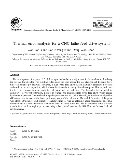
International Journal of Machine Tools&Manufacture39(1999)1087–1101Thermal error analysis for a CNC lathe feed drive system Won Soo Yun a,Soo Kwang Kim b,Dong Woo Cho a,*a Department of Mechanical Engineering,Pohang University of Science and Technology,San31Hyoja-dong,Nam-gu,Pohang,Kyungbuk790-784,South Koreab Group Department of Machine Industry,Pusan Information College,48-6Gupo-dong,Buk-gu,Pusan616-737,South KoreaReceived31March1998;received in revised form21September1998AbstractThe development of high-speed feed drive systems has been a major issue in the machine tool industry for the past few decades.The resulting reduction in the time needed for tool changes and the rapid travel time can enhance productivity.However,a high-speed feed drive system naturally generates more heat and resultant thermal expansion,which adversely affects the accuracy of machined parts.This paper divides the feed drive system into two parts:the ball screw and the guide way.The thermal behavior model for each part is developed separately,in order to estimate the position errors of the feed drive system caused by thermal expansion.The modified lumped capacitance method(MLCM)and genius education algorithm (GEA)are used to analyse the linear positioning error of the ball screw.Thermal deformation of the guide way affects straightness and introduces angular errors,as well as affecting linear positioning.Thefinite element method is used to estimate the thermal behavior of the guide way.The effectiveness of the proposed models is verified through experiments using a laser interferometer.©1999Elsevier Science Ltd.All rights reserved.Keywords:Angular error;Ball screw;Feed drive system;Guide way;Linear positioning error;Thermal deformationNomenclatureQ f(t)heat by frictionQ cl(t),Q cr(t),heat by conductionQ cn(t)*Corresponding author.Tel:ϩ82-562-279-2171;fax:ϩ82-562-279-5899;e-mail:dwcho@postech.ac.kr0890-6955/99/$-see front matter©1999Elsevier Science Ltd.All rights reserved.PII:S0890-6955(98)00073-X1088W.S.Yun et al./International Journal of Machine Tools&Manufacture39(1999)1087–1101Q h(t)heat by convectionmaterial densityT temperaturet timeV volumec specific heatK q torque coefficienti motor currentw¯rotational velocityT mea measured torqueT ana estimated torquefriction coefficientW distributed load along the nutr radius of the screw shaftqЉheatfluxk conduction coefficient1.IntroductionThe demand for high-speed/high-precision machine tools is rapidly increasing in response to the development of production technology that requires high-precision parts and high productivity. Research on high-speed machine tools can be approached from two directions:the main spindle or the feed drive system.In this research,a high-speed feed drive system was investigated in order to achieve rapid travel with improved precision.A high-speed feed drive system reduces non-cutting time and tool replacement time,making production more economical.However,it also generates more heat through friction at contact areas such as the ball screw and the guide ways,causing thermal deformation that subsequently degrades the accuracy of the machine tool. With this in mind,the thermal behavior of a feed drive system was investigated in order to develop a systematic method of analysis.It has been reported that thermal errors account for40ෂ70%of the total errors arising from various error sources[1].Research has considered a number of ways of reducing thermal error, including the thermally symmetric design of a structure,separation of the heat sources from the main body of the machine tool,cooling of the structure,compensation for the thermal error and so forth[2–9].However,accurate modelling of the heat source is quite difficult because of the constantly changing characteristics:the thermal inertia,the complexity of the machine tool struc-ture,etc.The research so far reported has therefore been unable to provide a satisfactory result. In the course of this research,thefinite element method(FEM)and thefinite difference method (FDM)have often been employed to estimate the thermal behavior of machine tools.However, they also show some significant differences between estimated and experimental results,which are attributed to the fact that it is difficult to establish the boundary conditions because of the complex shape of the structure and the varying heat generation rate[10,11].In the present research,the thermal error of the feed drive system was estimated by separately modelling the thermal behaviors of the ball screw and the guide way,and then subsequently evaluating the1089 W.S.Yun et al./International Journal of Machine Tools&Manufacture39(1999)1087–1101 eventual thermal deformation of the tool position.The ball screw was modelled by applying the modified lumped capacitance method(MLCM)[12,13]developed previously to estimate thermal deformation in real-time.The thermal deformation of the guide way was evaluated using FEM with boundary conditions obtained experimentally.The developed thermal model was applied to a CNC lathe to ascertain its effectiveness.2.Thermal error analysis for the ball screw systemTo meet the requirements of high accuracy and great rigidity,applying a preload between double nuts is used as a way to restrict the backlash of the ball screw[14].The frictional resistance between the screw shaft and the nut is increased by this preload.This generates greater heat, leading to thermal deformation of the ball screw and causing low positioning accuracy.Conse-quently,the accuracy of the main system,such as a machine tool,is degraded.Therefore,the thermal deformation of the ball screw is one of the most important things to consider for high-accuracy,high-speed machine tools[1,15,16].The present paper reports the development of a model that is able to estimate this thermal deformation in real-time.The deformation was assumed to occur only in the feed direction,caus-ing positioning error.2.1.Modified lumped capacitance method(MLCM)The thermal deformation of a ball screw can be compensated if the position of the nut can be accurately measured.However,m order measurement requires expensive equipment such as a laser interferometer,the actual implementation of which is not easy because of the effects of the hostile environment such as machine tool vibration and so on.Alternatively,if the temperature distribution can somehow be obtained,the corresponding thermal deformation can then be calcu-lated.However,to do so requires that the temperature be measured at all points on the screw shaft,which is almost impossible because of the structure of ball screws.The following describes the derivation of a proposed real-time heat transfer model that makes real implementation easier. The model was named the modified lumped capacitance method(MLCM).FEM analysis and experiments verified that both the nut and the screw have almost uniform temperature distribution in a radial direction[12,13].The real-time model estimates the tempera-ture of the screw by measuring the temperature only at those locations where sensors can be mounted even during feed motion,such as at the nut surface,inside the nut and at the support bearings at both ends.Simplifying the system into a lumped model,as shown in Fig.1,the following equation can be derived:Q f(t)ϩQ cl(t)ϩQ cr(t)ϪQ h(t)ϩQ cn(t)ϭcV dTdt(1)Using the above equation can produce large errors when estimating temperature,because of the inherent error involved with a lumped model and the inexact heat transfer coefficients.Therefore, compensation coefficients were introduced and multiplied to each and every term:1090W.S.Yun et al./International Journal of Machine Tools&Manufacture39(1999)1087–1101Fig.1.Schematic diagram for MLCM model.␣s Q f(t)ϩ␣lb Q flb(t)ϩ␣rb Q frb(t)ϩ␦Q cl(t)ϩ␦Q cr(t)Ϫ1b Q hs(t)(2)Ϫ2b Q hm(t)Ϫ1Q hs(t)Ϫ2Q hm(t)ϩ␥Q cn(t)ϭcV dTdtwhere␣s compensates for the inexact conjecture of the ratio of the power consumed by the friction between the screw and nut to the total motor,and for some unexpected heat generation.␣lb and ␣rb are the compensation coefficients for the heat generated at the left and right support bearings, respectively.1,2were introduced to compensate for environmental/shape factors and the heat transfer coefficients at the boundary.1b,2b represent the compensation coefficients at the support bearings in the same manner.␥compensates for the conduction coefficient.Finally,to compensate for any error due to simplifying the heat transfer between the screw and the nut,␦was introduced. Once the frictional heat source(Q f)and MLCM compensation coefficients are determined in Eq.(2),the temperature distribution on the screw and resulting thermal deformation can be obtained.2.2.Estimation of frictional heat(Q f)and MLCM compensation coefficientMotor torque must overcome basic motor torque for rotation,bearing friction and friction between the screw shaft and nut.Through some preliminary experiments,the portion of the total motor torque attributable to overcoming ball screw friction was assigned.Since the torque can be obtained by multiplying the measured motor current by the given torque coefficient,the fric-tional heat between the screw and the nut can be calculated byQ fϭ(K q·i)w¯(3)ϭT mea·w¯Fig.2shows a single axis feed drive system that consists of a ball screw and a feed motor. The ball screw was of grade C5,the backlash of which is less than0.005mm,and the maximumW.S.Yun et al./International Journal of Machine Tools&Manufacture39(1999)1087–11011091Fig.2.Testbed for the thermal behavior analysis of a ball screw system.feed speed was18m/min.Temperatures were measured during motion,with T-type thermocouples with0.1s response characteristics.After experimentally determining the frictional heat using Eq.(3),the MLCM compensation coefficients were obtained byfitting the model(Eq.(2))to the measured temperature data.A new optimization technique was developed and applied to minimize the error between the model and the measured data.It was named the genius education algorithm(GEA)[13,17]and was shown to be able to solve various optimization problems with good speed and reliability.It also excludes the need for computing derivatives and lessens the difficulty of determining parameter values. In the present research,the MLCM compensation coefficients were obtained through conducting experiments on a test bed and applying the GEA.Fig.3shows comparisons between the tempera-tures estimated by the MLCM model and the measured temperatures.The estimation was quite accurate,with the error bounded within3%,which validates the proposed scheme—the MLCM model with determining compensation coefficients using GEA.2.3.Thermal deformation error of the ball screwThe developed algorithm is applied to a two-axis CNC lathe.Thermal deformation analysis is performed regarding the z-axis only.Fundamental specification is as in Table1.Since it is almost impossible to measure the temperatures at the suggested points,the MLCM compensation coefficients and the frictional heat can not be estimated by measuring the tempera-ture and motor current as described.However,the main need for the compensation coefficients is because of the inexactness of the heat transfer coefficients.Since they do not change drastically for the same type of nut and screw structure,the compensation coefficients,other than the heat generation term,can be experimentally determined on a test bed.The frictional heat generation term needs to be evaluated by an analytical model because it differs for each machine tool.The following equation can be used to obtain the torque and the frictional heat due to the friction between the screw and the nut:T anaϭ͐Wrdx1092W.S.Yun et al./International Journal of Machine Tools&Manufacture39(1999)1087–1101parison with measurement and MLCM analysis(420rpm,stop time:1s).Table1The specification for a ball screw system of a CNC latheScrew shaft length1060mmNut length(one side)60mmPreload200kgfStroke400mmNut type Double nutQ fϭT ana·w¯(4)ϭ͐Wrw¯dxThe load distribution W varies with respect to the preload given to the nut as well as the specifications(nut length,ball diameter,screw shaft radius,lead angle,etc.)of the ball screw system concerned.Hence,the frictional torque and heat can be evaluated by the above equation after calculating the load distribution[13].In this paper,␣s in Eq.(2)was corrected by comparing the calculated frictional heat with that measured on a test bed.The frictional heat of the machine tool concerned can subsequently beW.S.Yun et al./International Journal of Machine Tools&Manufacture39(1999)1087–11011093Fig.4.Load distribution along the nut.calculated from the corrected␣s and the load distribution W along the z-axis of the machine.Fig. 4shows the load distribution along the z-axis.The preload imposed was200kgf.Each nut was 60mm long and of double nut structure.The total length of the nut was thus120mm.Fig.4 represents the load distribution of the left nut,and because of the symmetry the other nut has the same distribution.The distribution in Fig.4can be substituted in Eq.(4)to determine the heat generated.Based on the preceding derivation,thermal analysis of a ball screw system was performed and the results are illustrated in Figs.5and6.The feed conditions used for both the analysis and the experiment are shown in Table2.Thefigures show the thermal errors within the stroke range,with the errors being represented relative to the machine origin.Fig.5shows the temperature distribution estimated by substituting the calculated frictional heat and the corrected compensation coefficients in Eq.(2).The tempera-ture rises by7.55°C after30min operation for the z-axis stroke of400mm.Fig.6shows the errors due to thermal expansion within the stroke range.The error was measured with respect to a reference position,which was set to beϪ10mm from the machine origin,both in the estimation and in the experiment.The maximum error,34.2m,occurred at the end of the stroke.It was assumed that the thermal error of the ball screw system consists of only linear axial error.Fig.5.Temperature rise at z-axis screw shaft of the CNC lathe.1094W.S.Yun et al./International Journal of Machine Tools&Manufacture39(1999)1087–1101Fig.6.Thermal deformation of z-axis screw shaft of the CNC lathe.Table2The feeding condition for the analysis and experiment of the CNC latheFeeding velocity12m/minStop time2sFeeding time30min3.Thermal error analysis of the guide wayThere has been little active research on the thermal behavior of the guide way,since its effect on a machine tool’s accuracy has been considered less significant.However,in most cases where a CNC lathe takes sliding guide ways,the heat generated between the sliding surfaces can signifi-cantly degrade positioning accuracy.Furthermore,the thermal error of the guide way causes angular errors such as roll,pitch and yaw,as well as linear positioning error,subsequently increasing the amount of error at the tool-tip.In this paper,FEM analysis is applied to estimate the thermal error of guide ways.The heat sources are estimated from experiments,to be used for FEM[18].3.1.Estimation of the heat source and the boundary condition for FEMThe guide ways of the object CNC lathe are modelled as shown in Fig.7,in order to estimate the temperature rise and the subsequent thermal deformation generated by the friction of sliding. The turret is placed on the x-axis carriage but is excluded from the FEM analysis due to its complexfixing condition and structure.Each element was a cube with eight nodes,a node on each corner of the cube.The number of nodes and elements was3670and2376,respectively. The following assumptions were made to perform thermal analysis by FEM:1.Machining is not performed,thus the chip effect is not considered.2.Heat conduction from the motors is replaced by heatfluxes.3.Heat generated between the sliding surfaces is replaced by heatfluxes directed to the surfacesof the sliding surface elements.1095W.S.Yun et al./International Journal of Machine Tools &Manufacture 39(1999)1087–1101Fig.7.Geometry model for the structure of the CNC lathe guide way.4.There is no thermal deformation in x -,y -,or z -direction on the bottom of the machine.According to the above assumptions,the heat sources of the guide ways were divided as fol-lows:1.Heat generated between the carriage and the guide block.2.Heat conducted from the feed drive motors.3.Heat conducted from the ball screw.The first of the above is the biggest heat source for the guide way,and changes as the feed velocity changes.Exact estimation of the heat generated imposes many difficulties.Therefore,the boundary conditions for FEM were replaced by the heat fluxes,which were calculated from the measured temperatures.Temperatures were measured at points 1and 2in Fig.7while the machine was running under the conditions in Table 2.The difference in the temperature rise between the two points was almost constant at 0.173°C,and the temperature rise at point 3and at point 4was measured to be 0.8°C and 1.53°C,respectively.For commercial machine tools,it is almost impossible to measure the temperatures at any other points on the guide way.The approximate heat flux can be estimated by using the following equation,along with the measured temperature values of points 1and 2:q ЉϭϪk dTdx (5)The heat flux estimated above was assumed to be conducted to the carriage,and the heat flux to the sliding surfaces of the guide block was determined according to the duration of contact.1096W.S.Yun et al./International Journal of Machine Tools&Manufacture39(1999)1087–1101Fig.8.Temperature distribution of the CNC lathe guide way after30min heat up.3.2.Thermal deformation error of the guide wayThe results of the FEM analysis are shown in Fig.8.Thefigure describes the thermal distri-bution of the guide way structure after the z-axis was run for30min with the feeding conditions in Table2.The maximum temperature rise was around3.4°C.Table3compares the FEM results with the values measured at the specified four locations.The thermal deformation at each node on the sliding surfaces A and B(Fig.7)can be evaluated using the results in Fig.8.The six error components(one linear positioning error,two straightness errors,three angular errors)asso-ciated with one axis of a machine tool can subsequently be identified.Fig.9represents the temperature distribution of the two slide surfaces(A and B)of the guide block along the z-axis.As can be seen in thefigure,the two distributions differ,causing angular errors while feeding along the z-axis.Fig.10shows the respective thermal deformations.In the machine tool concerned,the contact area of slide surface B is greater than that of A,and the machine tool itself is not a symmetrical structure.Some difference therefore appears,as might be expected,between the thermal expansion of slide surface A and slide surface B.The defor-mation that is in the direction of feed can be interpreted as the linear positioning error.Table3Comparison of temperature rise with measured and calculated valuesAfter30min heat up Measured value Calculated value(°C)(°C)Temperature difference of point1,20.1730.12Temperature rise of point30.8 1.06Temperature rise of point4 1.53 1.83W.S.Yun et al./International Journal of Machine Tools&Manufacture39(1999)1087–11011097Fig.9.Temperature rise of two slide surface of the guide way system.Fig.10.Z direction thermal deformation of two slide surface of the guide way system.Figs.11and12represent the thermal deformation errors on the slide surfaces A and B in the x-and y-axis,respectively.The results show that x-and y-axis straightness errors occur due to thermal deformation during motion in the z-axis.Pitch error is also induced by the thermal deformation,as shown in Fig.13.The bottom surfaceFig.11.X direction thermal deformation of two slide surface of the guide way system.1098W.S.Yun et al./International Journal of Machine Tools&Manufacture39(1999)1087–1101Fig.12.Y direction thermal deformation of two slide surface of the guide way system.Fig.13.X axis angular error in the YZ plane(pitch angle error).of the guide way was assumed to be not deformable,so that it could be used as a reference for pitch error.Fig.14illustrates the total amount of error,together with the individual error components,of a ball screw and guide way of a feed drive system.Fig.14(a)shows the estimated tool tip errorFig.14.Z axis linear positioning error due to the thermal deformation of the feed drive system.W.S.Yun et al./International Journal of Machine Tools&Manufacture39(1999)1087–11011099 induced by the pitch angle error of the guide way.It was viewed that a guide block simply guides the carriage block without constraints.Therefore,thermal expansion of the guide block does not give rise to linear positioning error of the tool-tip,whereas pitch angle error does,as in Fig. 14(a).The tool-tip is located300mm from the guide block along the y-axis,and is thus signifi-cantly affected by pitch angle error.Fig.14shows that the maximum tool-tip thermal error at the end of the stroke is10.04m.The remaining angle errors,such as roll and yaw errors,appear to be negligibly small.The results are not shown in this paper.4.Thermal deformation error of the feed drive systemTo predict the linear positioning error of a tool(cutting point)in a CNC lathe,the thermal expansion of the ball screw and of the guide way should be added together.Fig.14(c)represents the total tool-tip error caused by the thermal deformation of the feed drive system,which was obtained by summing the individual errors:the error due to ball screw expansion(Fig.14(b))and the pitch angle error due to guide way deformation(Fig.14(a)).The resulting maximum linear positioning error due to thermal deformation was44.24m.The linear positioning error during z-axis feeding was measured in the CNC lathe concerned using a laser interferometer,for comparison with the calculated results.The measured values of the linear positioning error are shown in Fig.15.The positioning error was measured immediately after the machine was turned on and again after30min movement,under the conditions in Table 2.The former was subtracted from the latter and this difference was taken as the error due to thermal deformation.As can be seen in thefigure,the z-axis stroke was400mm and the error was measured every20mm.The maximum thermal error within a stroke turned out to be40.45m. Fig.16compares the experimental and the estimated thermal errors during z-axis feeding.The proposed scheme of analysis,which combines the individual errors of the ball screw and the guide way in the aforementioned manner,estimates the errors caused by the thermal deformation of the feed drive system with surprising accuracy.Through estimation and experiment,it was shown that the thermal error due to the pitch angleFig.15.Experimental results using the laser interferometer.1100W.S.Yun et al./International Journal of Machine Tools&Manufacture39(1999)1087–1101parison between the estimated and experiment results.error of the guide way accounted for22.7%of the total thermal error.The guide way should therefore be taken into account to estimate thermal error accurately.5.ConclusionsThis paper proposes a method of estimating the tool-tip error caused by the thermal errors of a feed drive system.The approachfirst individually models and calculates the thermal errors of the ball screw and the guide way structures using MLCM/GEA and FEM,respectively,and then adds them together.The ball screw gives rise to only linear positioning errors,whereas the guide way causes angular errors as well as linear positioning and straightness errors.Of all the angular errors,it is the pitch angle error that most affects the linear positioning error at the tool-tip.For better thermal analysis of a feed drive system,the guide way as well as the ball screw should be taken into account.Using the proposed scheme,the thermal error of a ball screw system can be found with only its specifications,and the heatflux of the guide way system can easily be obtained by experiment and then used for FEM analysis.The effectiveness of the proposed models was proven through experiments,with an accuracy of3.79m at the end of the stroke.AcknowledgementsThis research was funded by the Machine Tool Division of Daewoo Heavy Industries Ltd.,and many of the experiments were conducted using their machine tools in their plant.The authors are sincerely grateful to the persons concerned.References[1]J.B.Bryan,Ann.CIRP39(1990)645–656.[2]G.Spur,E.Hoffman,E.Paluncic,K.Benzinger,H.Nymoen,Ann.CIRP37(1988)401–405.1101 W.S.Yun et al./International Journal of Machine Tools&Manufacture39(1999)1087–1101[3]J.S.Chen,J.X.Yuan,J.Ni,S.M.Wu,Trans.Am.Soc.Mech.Engrs.,J.Engng.for Industry115(1993)472–479.[4]A.Kurtoglu,Ann.CIRP39(1990)417–419.[5]Y.Hatamura,T.Nagao,M.Mitsuishi,K.Kato,S.Taguchi,T.Okumura,Ann.CIRP42(1993)549–552.[6]J.S.Chen,Int.J.Mach.Tools Manufact.35(1995)593–605.[7]S.C.Veldhuis,M.A.Elbestawi,Ann.CIRP44(1995)373–377.[8]M.Weck,Ann.CIRP44(1995)589–598.[9]T.Moriwaki,C.Zhao,Proceedings of8th International IFIP WG5.3Conference,PROLAMAT’92,Japan(1992).[10]M.Weck,L.Zangs,Proceedings of the16th MTDR Conference16(1975)185–194.[11]T.Moriwaki,Ann.CIRP37(1988)393–396.[12]S.K.Kim,D.W.Cho,Int.J.Mach.Tools Manufact.37(1997)451–464.[13]S.K.Kim,Real-time estimation of temperature distribution in a ball screw system.PhD Thesis,Pohang Universityof Science and Technology(POSTECH),1997.[14]K.Takafuji,K.Nagashima,Jap.Soc.Mech.Engrs.33(1990)620–626.[15]J.Otsuka,S.Fukada,N.Obuchi,Jap.Soc.Precision Engng.50(1984)8–13.[16]L.M.Kordysh,L.V.Margolin,Soviet Engng.Res.54(5)(1983)22–24.[17]S.K.Kim,D.W.Cho,Genius education algorithm:a new global optimization method.IEEE Trans.Sys.,ManCybernet.,(in preparation).[18]abaqus version5.3manual.Hibbitt,Karlsson and Sorensen,Inc.。
分析数控机床改造外文文献翻译、中英文翻译、外文翻译

Analysis of transformation of numerical controlmachine toolIn order to survival and development of enterprises, improve the rate of CNC machine tools is necessary. Transformation of the equipment needed for NC machine tools in general, including traditional and recently introduced from abroad, due to a problem can not be put into the machine tool equipment and production lines. First, transform the contents of the NCCNC machine tools and production line transformation of the main contents are: (1) restoration of the original function, machine tools, production lines there is some fault diagnosis and recovery; (2)NC-based, in the general machine tools addend remarkable device or add numerical control system; ( 3) The renovation, to improve accuracy, efficiency and degree of automation, mechanical, electrical parts of the renovation, the mechanical part of there-assembly process, to restore the original precision; can not meet the production requirements of its CNC system be updated with the latest CNC; (4) technology updates or technical innovation, in order to improve performance or grade, or for the use of new technology, new technology, based on the original large-scale technology updates or technical innovation.Second, the development trend of CNC systeml. To open, the sixth generation of PC-based directionThe openness of the PC-based, low-cost, high reliability, rich in natural resources such as hardware and software features, and more CNC system manufacturer will be to go down this path. At least with PC, as its front-end machines, to deal with man-machine interface, programming, networking and communications issues, the original system to take over some tasks PC CNC machines has the friendly interface, will reach all of the CNC system. The remote communication, remote diagnostics and maintenance of applications will be more common.2. To the development of high-speed and high precision.3. To the intelligent direction(1) The application of adaptive control technology. Numerical control system can detect the process of important information and automatically adjust system parameters, improving the system operation status.2) the introduction of expert systems to guide processing. Will be skilled workers and expertise, processing and general laws and special laws into the system to process parameter database support, establish an artificial intelligence expert system.(3) the introduction of fault diagnosis expert system(4) intelligent digital servo drives. Can automatically identify the load and automatically adjust the parameters of the drive system to get the best state of operation.Third, the choice of numerical control system1. Open-loop systemThe system's servo-driven device is a stepper motor, power stepper motors, electro-hydraulic pulse motors. This system does not require position and velocity feedback, displacement accuracy depends mainly on the angular displacement precision stepper motor and gear drive components such as precision screw, so displacement of low accuracy. But the system is simple, debugging easy maintenance, reliable, low cost, easily converted successfully.2. Closed-loop systemThe system consists of grating, sensor position detection device synchronization, etc. The actual measured position signal fed back to the computer, compared with a given value, the difference between the two amplification and transformation, driving the implementing agencies in order to eliminate bias. The system complexity, high cost and strict temperature requirements on the environment. But thesystem of high precision, speed and big power. According to technological requirements and decide whether to adopt.3. Semi-closed-loop systemSemi-closed-loop system detects components installed in the middle of transmission parts, the indirect measurement of the location of the implementation of parts. It can only compensate for part of the components within the system loop error, and therefore its more accurate than the accuracy of closed-loop system is low, but its structure and debugging as compared with the closed-loop system is simple.Current production numerical control system are more companies and manufacturers, foreign companies such as Siemens of Germany, Japan, Fanuc, Inc.; domestic Everest companies such as China, the Beijing Aerospace CNC System Corporation, Huazhong CNC CNC high-grade corporate and Shenyang National Engineering Research Center. Select CNC systems are mainly based on numerical control after transformation to be achieved in a variety of precision machine tools, drive motor power and the user's requirements to determine. Fourth, the main steps CNC transformation1. Determination of rehabilitation programs(1) Mechanical and Electrical Repair transformation combined.Generally speaking, in need of transformation of electrical machines, are in need of mechanical repair. To determine repair requirements, scope and content; have to ascertain the electrical modification of the mechanical structure in need of transformation requirements and content; but also determine the transformation of electrical and mechanical repair, reconstruction staggered between the time requirements. Mechanical properties of intact are electrical transformation success.(2) the easier issues first, after the first partial overall. Determine the transformation step, the whole electrical part of the transformation should be divided into several sub-systems, the basic shape of various systems to be connected after the completion of the whole system work. In each subsystem, we should do first the less technical, workload the larger work, and then do a technical high, requiring fine work, can focus people's attention to key areas.(3) selection system under conditions of use. For the transformation of the object to determine its environment and conditions, which the selection of electrical system protection, anti-jamming, self-cooling and air filtering performance can provide the correct basis. Electrical system options must also be considered mature products, their performance should be reasonable and practical, there are spare parts to provide maintenance support, features a number of years to meetthe current and future development requirements.(4) The implementation and responsibilities of personnel involved in reconstruction.(5) The transformation of the determination of the scope and cycle.2. Transformation of the technical preparation(1) mechanical parts ready. In line with the transformation of mechanical electrical repairs should be completed in advance. The same time, be demolished and replaced and processing should be part of such advance planning is necessary to properly interface with the entire transformation.(2) The electrical information on the new system to digest.(3) The conversion of the old system interface design. According to the scope of each of the different equipment modification required to pre-designed interface, part of the conversion, if the entire transformation should be designed to convert mechanical and electrical interfaces, operation panel control and configuration, the Internet part of the contact, parameter measurement, the maintenance and so on. Require the operation and maintenance easy and reasonable, alignments, fluent, primary and secondary connection point less electrical interference with the strength of the smallest, with an appropriate margin and so on. Local transformation, but also need to consider the performance of the system match theold and new, the voltage polarity and size of change, the installation location, digital-analog conversion, etc., if necessary, need to create their own interfaces.(4) operation and programming staff technical training. ①training should cover the new control panel configuration, function and meaning of the instructions; ②the scope of the new system features, use, and the difference between the old system; ③maintenance requirements; ④programming standards and automated programming and more. Focused understood, grasp operating instructions and programming instructions.(5) Debugging steps and acceptance criteria for the determination. Debugging should be done by the project leader carried out with the others. Debugging step can be from simple to complex, from small to large, from outside to inside, you can also after the first local situation, the whole system after the first subsystem. The development of acceptance criteria must be realistic, too high or too low a standard will have a negative impact on the transformation.3. The implementation of reform(1) The overall maintenance of the machine. The long-term use of the original machine, you need to conduct a comprehensive maintenance. Secondly, the response to machine tools to make achange before the geometric accuracy, dimensional accuracy of measurement, and for the record. In this way pairs of reference to guide the transformation of the role, but also in the transformation of the end for comparison analysis.(2) to retain the electrical adjustment of some of the best. If the electrical system as part of the transformation, in turn, should retain the parts of the maintenance and optimization adjustments, such as high power part of the spare parts replacement, electrical maintenance, drying transformer insulation, pollution, cleaning, ventilation and cooling equipment cleaning, servo Drive optimization adjustments, update aging wires and cables, connectors and other fastening. Only the electrical part of the reservation and do excellent optimization adjustment, in order to ensure that transformed the machine tool have lower failure rates.(3) The original systems were dismantled. The removal of the original system must be controlled carefully to the original drawings in time to make mark in the drawings to prevent the omission or been demolished. In the process of demolition will find some of the new system design in the gaps, it is timely to add and correction. Removed the system should be properly safeguarded in case of unsuccessful reconstruction resume use. There is a definite value, and can be used for spare parts.(4) reasonable arrangements for the location and wiring the new system. Connection must be a clear division of labor, there is one person review the inspection to ensure that the connection process specifications, diameter suitable, correct, reliable and beautiful. (5) debugging. Debug must be pre-established procedures and requirements. Debugging the first to test the safety protection system sensitivity, personal and equipment to prevent accidents. Debugging the site must be clean; the moving coordinate extension units at the center of the whole trip; be able to load test, the first no-load after load; can simulate the experiment, the first real action after simulated; be manual, first manually and automatically.4. Acceptance and post-work(1) The mechanical properties of machine tool acceptance. Machine tool should meet the requirements of the mechanical properties, geometric accuracy should be within the limits prescribed.(2) The electrical control functions and control accuracy and acceptance. The various functions of electrical control actions must meet the normal, sensitive and reliable. Control precision application system itself functions (such as step size, etc.) and standard measuring apparatus (such as laser interferometer, coordinate measuring machine, etc.) control checks, to reach within a range. Should also be modified before the machine with the functions andaccuracy to make comparison, access to quantifiable indicators of difference.(3) The test piece cutting and acceptance. Can refer to the relevant domestic and international standards for CNC cutting specimens, in a qualified operator, the programmer with the trial under the cut. Specimen cutting machine tools can be acceptance of stiffness, cutting force, noise, motion trajectory, related actions, are generally not suitable for specimen use of a product part.(4), drawings, information and acceptance. Machine transformation finished, should be promptly drawings, data, transform the file summary, collate, transfer into the file. This is the future and stable operation of the equipment is very important.(5) Summary and improve.5, numerical examples of reconstruction1. Milling machine with the Siemens 810M transformation X53In 1998, the company invested 200,000 yuan, with Germany's Siemens 810M CNC system, 611A AC servo drive system on the company's X53 model of a milling machine to X, Y, Z three-axis numerical control transformation. Retained the original spindle system and cooling system. -Axis transformation of a ball screw used in the machinery and gear transmission mechanism. Thetransformation of work includes mechanical design, electrical design, PLC program preparation and debugging, machine tool repair, machine installation and debugging. After transformation, milling, processing and effective travel X, Y, Z axis respectively, 880mm, 270mm, 280mm; maximum speed of X, Y, Z axis respectively, 5 000mm/min, 1 500mm/min, 800mm/min; point moving speed of X, Y, Z axis respectively 3 000mm/min, 1 000mm/min, 500 mm / min; machining accuracy of ± 0.001 mm. Machine tools, coordinate linkage to be completed by a variety of complex curve or surface processing.2. GSK980T and stepper drive system with the transformation ofC6140 latheIn 1999, the company invested 8 million yuan, with Guangzhou CNC Equipment Factory production GSK980T numerical control system, DY3 hybrid stepper drive unit on the company's a longerC6140 lathe X, Z 2-axis transform. Retained the original spindle system and cooling system. Transformation of two-axis ball screw in the machinery used, and synchronous transmission. The transformation of work includes mechanical design, electrical design, machine overhaul and machine installation and debugging. Lathe After the transformation, processing and effective stroke X, Z axis respectively, 390mm, 1400mm; maximum speed X, Z axisrespectively, 1 200mm/min, 3 000mm/min; jog speed 400mm/min; point moving fast X, Z-axis respectively, 1 200mm/min, 3000mm/min; machine smallest mobile unit 0.001mm.6, numerical transformation of the issues and recommendations1. Transformation problems in NCCNC machine tools through several transformation and found work, there are also many problems, mainly reflected in: (a) The departments, developers uncertain functions, organizational chaos, a serious impact on progress in the transformation; (2) to develop the work process and plans are mostly developed rule of thumb, less reasonable; (3) the training of relevant personnel is not in place, resulting in machine tool technology officers will not be modified after programming, the operator of the machine operator unskilled and so on.2. Transformation of the proposed NC(1) is responsible for transformation of the staff responsibilities of clear penalties and rewards, fully mobilize the enthusiasm of the staff; train a batch of high-quality applications and maintenance personnel, training for selected officers to go out and learn the advanced technologies;(2) To focus on users, maintenance of CNC system of technicaltraining, the establishment of numerical control technology at home and abroad resource library. The establishment of technical data files, do the work of spare parts.分析数控机床改造为了我国民营企业的生存与发展,提高数控机床的速度是必要的。
机床——机械类外文文献翻译、中英文翻译
毕业设计(论文)外文资料翻译系部:专业:姓名:学号:外文出处:English For Electromechanical(用外文写)Engineering附件:1.外文资料翻译译文;2.外文原文。
附件1:外文资料翻译译文机床机床是用于切削金属的机器。
工业上使用的机床要数车床、钻床和铣床最为重要。
其它类型的金属切削机床在金属切削加工方面不及这三种机床应用广泛。
车床通常被称为所有类型机床的始祖。
为了进行车削,当工件旋转经过刀具时,车床用一把单刃刀具切除金属。
用车削可以加工各种圆柱型的工件,如:轴、齿轮坯、皮带轮和丝杠轴。
镗削加工可以用来扩大和精加工定位精度很高的孔。
钻削是由旋转的钻头完成的。
大多数金属的钻削由麻花钻来完成。
用来进行钻削加工的机床称为钻床。
铰孔和攻螺纹也归类为钻削过程。
铰孔是从已经钻好的孔上再切除少量的金属。
攻螺纹是在内孔上加工出螺纹,以使螺钉或螺栓旋进孔内。
铣削由旋转的、多切削刃的铣刀来完成。
铣刀有多种类型和尺寸。
有些铣刀只有两个切削刃,而有些则有多达三十或更多的切削刃。
铣刀根据使用的刀具不同能加工平面、斜面、沟槽、齿轮轮齿和其它外形轮廓。
牛头刨床和龙门刨床用单刃刀具来加工平面。
用牛头刨床进行加工时,刀具在机床上往复运动,而工件朝向刀具自动进给。
在用龙门刨床进行加工时,工件安装在工作台上,工作台往复经过刀具而切除金属。
工作台每完成一个行程刀具自动向工件进给一个小的进给量。
磨削利用磨粒来完成切削工作。
根据加工要求,磨削可分为精密磨削和非精密磨削。
精密磨削用于公差小和非常光洁的表面,非精密磨削用于在精度要求不高的地方切除多余的金属。
车床车床是用来从圆形工件表面切除金属的机床,工件安装在车床的两个顶尖之间,并绕顶尖轴线旋转。
车削工件时,车刀沿着工件的旋转轴线平行移动或与工件的旋转轴线成一斜角移动,将工件表面的金属切除。
车刀的这种位移称为进给。
车刀装夹在刀架上,刀架则固定在溜板上。
溜板是使刀具沿所需方向进行进给的机构。
数控车床外文翻译3
本科生毕业设计 (论文)
外文翻译
原文标题数控车床
译文标题Numerical Control Lathes
作者所在系机械工程系
作者所在专机械设计制造及其自动化作者所在班
作者姓名
作者学号
指导教师姓
指导教师职
完成时间2012 年 2 月28
注:1. 指导教师对译文进行评阅时应注意以下几个方面:①翻译的外文文献与毕业设计(论文)的主题是否高度相关,并作为外文参考文献列入毕业设计(论文)的参考文献;②翻译的外文文献字数是否达到规定数量(3 000字以上);③译文语言是否准确、通顺、具有参考价值。
2. 外文原文应以附件的方式置于译文之后。
机械类车床外文翻译
毕业设计(论文)——外文翻译(原文)Lathe来源:/wiki/LatheA lathe is a machine tool which spins a block of material to perform various operations such as cutting, sanding, knurling, drilling, or deformation with tools that are applied to the workpiece to create an object which has symmetry about an axis of rotation.Lathes are used in woodturning, metalworking, and glassworking. Lathes can be used to shape pottery, the best-known design being the potter's wheel. Most suitably equipped metalworking lathes can also be used to produce most solids of revolution, plane surfaces and screw threads or helices. Ornamental lathes can produce three-dimensional solids of incredible complexity. The material is held in place by either one or two centers, at least one of which can be moved horizontally to accommodate varying material lengths. Examples of objects that can be produced on a lathe include cue sticks, table legs, bowls, baseball bats, crankshafts and camshafts.HistoryThe lathe is an ancient tool, dating at least to the Egyptians ,and known and used in Greece, the Roman and Byzantine Empires.The origin of turning dates to around 1300BC when the Egyptians first developed a two-person lathe. One person would turn the wood workpiece with a rope while the other used a sharp tool to cut shapes in the wood. The Romans improved the Egyptian design with the addition of a turning bow. Early bow lathes were also developed and used in Germany, France and Britain. In the Middle Ages a pedal replaced hand-operated turning, freeing both the craftsman's hands to hold the woodturning tools. The pedal was usually connected to a pole, often a straight-grained sapling. The system today is called the "spring pole" lathe. Spring pole lathes were in common use into the early 20th Century. A two-person lathe, called a "great lathe", allowed a piece to turn continuously (like today's power lathes). A master would cut the wood while an apprentice turned the crank。
关于数控车床编程外文文献翻译中英文翻译外文翻译
关于数控车床编程外文文献翻译、中英文翻译、外文翻译英文原文On the NC latheCNC machine tool numerical control machine tools (Computer numerical control machine tools) abbreviation, is provided with a program control system of automatic machine tools. The logic control system can deal with the control code or other symbolic instruction specified program, and decoding the digital code, said information carrier, through the numerical control device input. After processing by CNC device control signals, control the machine movements, by drawing the shape and size requirements, will be automatically processed by the parts.Features: CNC machine tool operation and monitoring of all completed inthe numericalcontrol unit, it is the brain of CNC machine tools. Compared with the general machine tools, CNC machine tools has the following characteristics:● the processing object adaptability, adapt to the characteristics of mold products such as a single production, provide the appropriate processing method for die and mould manufacturing; ● high machining accuracy, processing with stable quality; ● can coordinate linkage, processing complex shape parts;● machining parts change, only need to change the program, can save the preparation time of production;● the machine itself high precision, rigidity, can choose the am ount of processing good, high productivity (3~5 times as common machine);The machine is a high degree of automation, reducing labor intensity;● conducive to the production management modernization. The use of CNC machine tools and the standard code of digital information processing, information transmission, the use of computer control method, has laid the foundation for the integration of computer aided design, manufacturing and management;● on the operators of higher quality, higher demands for the repair ofthe technical staff;● high reliability.Composition: CNC machine tools in general by the input medium, man-machine interactive equipment, CNC equipment, feed servo drive system, spindle servo drive system, the auxiliary control device, feedback apparatus and adaptive control device etc.. [4] in NC machining, NC milling processing is the most complex, need to solve most problems. NC programming of NC line in addition to CNC milling, cutting, CNC EDM, CNC lathe, CNC grinding, each with its own characteristics, servo system is the role of the motion signal is convertedinto the machine moving parts from the numerical control device of pulse. Concrete has the following parts: the structure of CNC machine tools.Driver: he is driving parts of CNC machine tools, actuator, including spindle drive unit, feeding unit, spindle motor and feed motor. He through the electric or electro-hydraulic servo system to realize the spindle and feeddrive under the control of numerical control device. When several feed linkage, can complete the positioning, processing line, plane curve and space curve.The main performance (1) the main dimensions. (2) the spindle system. (3) feed system. (4) tool system.(5) electrical. Including the main motor, servo motor specifications and power etc.. (6) cooling system. Including the cooling capacity, cooling pump output. (7) dimensions. Expressed as length * width * height.Development trend of CNC lathe:High speed, precision, complex, intelligent and green is the general trend in the development of CNC machine tool technology, in recent years, made gratifying achievements in practicality and industrialization. Mainly in the:1 machine tool composite technology to further expand with the CNC machine tool technology, composite processing technology matures, including milling - car compound, car millingcompound, car - boring - drill - gear cutting compound, composite grinding, forming, composite processing, precision and efficiency of machining isgreatly improved. \processing factory\the development of compound processing machine tool is the trend of diversified.Intelligent technology 2 CNC machine tools have a new breakthrough, in the performance of NC system has been reflected more. Such as: automaticallyadjust the interference anti-collision function, after the power of workpiece automatically exit safety power-off protection function, machining parts detection and automatic compensation function of learning, high precisionmachining parts intelligent parameter selection function, process automatic elimination of machine vibration functions into the practical stage, intelligent upgrade the function of machine and quality.The 3 robots enable flexible combination of flexible combination of higher efficiency of robot and the host are widely used, make flexible line more flexible, extending the function, flexible line shorten further, more efficient. Robot and machining center, milling composite machine, grinder, gear processing machine tool, tool grinding machine, electric machine, sawing machine, punching machine, laser cutting machine, water cutting machine etc. various forms of flexible unit and flexible production line has already begun the application.4 precision machining technology has the machining precision of CNC metal cutting machine tools from the yarn in the original (0.01mm) up to micronlevel (0.001mm), some varieties has reached about 0.05 μ M. Micro cutting and grinding machining of ultra precision CNC machine tools, precision can reach about 0.05 μ m, shape precision can reach about 0.01 μ M. Special processing precision by using optical, electrical, chemical, energy can reach nanometer level (0.001 μ m). By optimizing the design of machine tool structure, machine tool parts of ultra precision machining and precision assembly, using high precision closed loop control andtemperature, vibration and other dynamic error compensation technology, improve the geometric accuracy of machine tool processing, reduce the shape of error, surface roughness, and into the submicron, nano super finishing tiThe 5 functional component to improve the performance of functional components are at a high speed, high precision, high power and intelligent direction, and obtain the mature application. A full digital AC servo motor and drive device, high technology content of the electric spindle, linear motor, torque motor, linear motion components with high performance, application of high precision spindle unit and other function parts, greatly improving the technical level of CNC machine tools.The feed drive system of CNC lathe: Effect of feed drive system,The feed drive system of CNC machine tools will be received pulse command issued by the numerical control system, and the amplification and conversion machine movements carry the expected movement.Two, the feeding transmission system requirementsIn order to guarantee the machining accuracy of NC machine tool is high,the feed drive system of transmission accuracy, sensitivity high (fast response), stable work, high stiffness and friction and inertia small, service life, and can remove the transmission gap. Category three, feed drive system 1, stepping motor servo system Generally used for NC machine tools. 2, DC servo motor servo systemPower is stable, but because of the brush, the wear resulting in use needto change. Generally used for middle-grade CNC machine tools. 3, AC servomotor servo systemThe application is extremely widespread, mainly used in high-end CNC machine tools. 4, the linear motor servo systemNo intermediate transmission chain, high precision, the feed speed, no length limit; but the poor heat dissipation, protection requirements are particularly high, mainly used for high-speed machine.Driving component four, feed system 1, the ball screw nut pairNC machining, the rotary motion into linear motion, so the use of screwnut transmissionmechanism. NC machine tools are commonly used on the ball screw, as shownin Figure 1-25, it can be a sliding friction into rolling friction, meet the basic requirements of the feed system to reduce friction. The transmissionside of high efficiency, small friction, and can eliminate the gap, no reverse air travel; but the manufacturing cost is high, can not lock, size is not too big, generally used for linear feed in small CNC machine tool. 2, rotary tableIn order to expand the scope of the process of NC machine tools, CNC machine tools in addition to make linear feed along the X, Y, Z three coordinate axes, often also need a circumferential feed movement around Y or Z axis. Circular feed motion of CNC machine tools in general by the rotary table to realize, for machining center, rotary table has become an indispensablepart of. Rotary table of commonly used CNC machine tools in the indexing table and NC rotary table. (1) indexing tableIndexing table can only finish dividing movement, not circular feed, it is in accordance with the instructions in the NC system, when indexing will work together with the workpiece rotation angle. When indexing can also use manual indexing. Provisions of indexing table is generally only rotary angle (such as 90, 60 and 45 degree). (2) NC rotary tableNC rotary table appearance similar to the indexing table, but the internal structure and function is not the same. The main function of the NC rotary table is based on the numerical control device sends command pulse signal, complete circumferential feed movement, various arc processing and surface processing, it can also be graduation work. 3, guideRail is an important part of feed drive system, is one of the basic elements of the structure of machine tool, rigidity, precision and accuracy of NC machine tool which determines to a large extent retention. At present, guide the NC machine tool are sliding rail, rolling guideway and hydrostatic guideway. (1) sliding guideSliding guide rail has the advantages of simple structure, easy manufacture, good stiffness, vibration resistance and high performance, widely used in CNC machine tools, the use of most metal plastic form, known as the plastic guide rail, as shown in figure 1-26.On characteristics of the plastic sliding guide: friction characteristicis good, good wear resistance, stable movement, good manufacturability, low speed. (2) rolling guideRolling guide is placed in the rail surface between the ball, roller or needle roller, roller, the rolling friction instead of sliding surface of the guide rail between wipe.Rolling guide rail and the sliding rail, high sensitivity, small friction coefficient, and the dynamic, static friction coefficient is very small, so the motion is uniform, especially in the low speed movement, the stick-slip phenomenon is not easy to occur; high positioning accuracy,repeatability positioning accuracy is up to 0.2 μ m; traction force is small, wear small, portable in movement; good precision, long service life. But the vibration of rolling guide, high requirements on protection, complicated structure, difficult manufacture, high cost.Automatic tool changer:One, the function of automatic tool changerAutomatic tool changing device can help save the auxiliary time of CNC machine tools, and meet in an installation completed procedure, stepprocessing requirements. Two, on the requirement of automatic tool changerNumerical control machine tool for automatic tool changer requirement is: tool change quickly, time is short, high repetitive positioning accuracy, tool storage capacity is sufficient, small occupation space, stable and reliable work. Three, change the knife form 1, rotary cutter replacementIts structure is similar to the ordinary lathe turret saddle, according to the processing of different objects can be designed into square or six angle form, consists of the NC system sends out the instruction to the rotary cutter.2, the replacement of the spindle head tool changeThe spindle head pre-loaded required tools, in order to machining position, the main motor is switched on, drives the cutter to rotate. The advantage of this method is that eliminates the need for automatic clamping, cutting tool, clamping and cutting tool moving and a series of complex operation, reducetool change time, improve The ATC reliability. 3, the use of changing toolThe processing required tools are respectively arranged in the standard tool, adjust the size of the machine after certain way add to the knife, the exchange device from the knife and the spindle take knife switch.感谢您的阅读,祝您生活愉快。
- 1、下载文档前请自行甄别文档内容的完整性,平台不提供额外的编辑、内容补充、找答案等附加服务。
- 2、"仅部分预览"的文档,不可在线预览部分如存在完整性等问题,可反馈申请退款(可完整预览的文档不适用该条件!)。
- 3、如文档侵犯您的权益,请联系客服反馈,我们会尽快为您处理(人工客服工作时间:9:00-18:30)。
LathesLathes are machine tools designed primarily to do turning, facing and boring, Very little turning is done on other types of machine tools, and none can do it with equal facility. Because lathes also can do drilling and reaming, their versatility permits several operations to be done with a single setup of the work piece. Consequently, more lathes of various types are used in manufacturing than any other machine tool.The essential components of a lathe are the bed, headstock assembly, tailstock assembly, and the leads crew and feed rod.The bed is the backbone of a lathe. It usually is made of well normalized or aged gray or nodular cast iron and provides s heavy, rigid frame on which all the other basic components are mounted. Two sets of parallel, longitudinal ways, inner and outer, are contained on the bed, usually on the upper side. Some makers use an inverted V-shape for all four ways, whereas others utilize one inverted V and one flat way in one or both sets, They are precision-machined to assure accuracy of alignment. On most modern lathes the way are surface-hardened to resist wear and abrasion, but precaution should be taken in operating a lathe to assure that the ways are not damaged. Any inaccuracy in them usually means that the accuracy of the entire lathe is destroyed.The headstock is mounted in a foxed position on the inner ways, usually at the left end of the bed. It provides a powered means of rotating the word at various speeds . Essentially, it consists of a hollow spindle, mounted in accurate bearings, and a set of transmission gears-similar to a truck transmission—through which the spindle can be rotated at a number of speeds. Most lathes provide from 8 to 18 speeds, usually in a geometric ratio, and on modern lathes all the speeds can be obtained merely by moving from two to four levers. An increasing trend is to provide a continuously variable speed range through electrical or mechanical drives.Because the accuracy of a lathe is greatly dependent on the spindle, it is of heavy construction and mounted in heavy bearings, usually preloaded tapered roller or ball types. The spindle has a hole extending through its length, through which long bar stock can be fed. The size of maximum size of bar stock that can be machined when the material must be fed through spindle.The tailsticd assembly consists, essentially, of three parts. A lower casting fits on the inner ways of the bed and can slide longitudinally thereon, with a means for clamping the entire assembly in any desired location, An upper casting fits on the lower one and can be moved transversely upon it, on some type of keyed ways, to permit aligning the assembly is the tailstock quill. This is a hollow steel cylinder, usually about 51 to 76mm(2to 3 inches) in diameter, that can be moved several inches longitudinally in and out of the upper casting by means of a hand wheel and screw.The size of a lathe is designated by two dimensions. The first is known as the swing. This is the maximum diameter of work that can be rotated on a lathe. It is approximately twice the distance between the line connecting the lathe centers and the nearest point on the ways, The second size dimension is the maximum distance between centers. The swing thus indicates the maximum work piece diameter that can be turned in the lathe, while the distance between centers indicates the maximum length of work piece that can be mounted between centers.Engine lathes are the type most frequently used in manufacturing. They are heavy-duty machine tools with all the components described previously and have power drive for all tool movements except on the compound rest. They commonly range in size from 305 to 610 mm(12 to 24 inches)swing and from 610 to 1219 mm(24 to 48 inches) center distances, but swings up to 1270 mm(50 inches) and center distances upto 3658mm(12 feet) are not uncommon. Most have chip pans and a built-in coolant circulating system. Smaller engine lathes-with swings usually not over 330 mm (13 inches ) –also are available in bench type, designed for the bed to be mounted on a bench on a bench or cabinet.Although engine lathes are versatile and very useful, because of the time required for changing and setting tools and for making measurements on the work piece, thy are not suitable for quantity production. Often the actual chip-production tine is less than 30% of the total cycle time. In addition, a skilled machinist is required for all the operations, and such persons are costly and often in short supply. However, much of the operator’s time is consumed by simple, repetitious adjustments and in watching chips being made. Consequently, to reduce or eliminate the amount of skilled labor that is required, turret lathes, screw machines, and other types of semiautomatic and automatic lathes have been highly developed and are widely used in manufacturing.2 Numerical ControlOne of the most fundamental concepts in the area of advanced manufacturing technologies is numerical control (NC). Prior to the advent of NC, all machine tools ere manually operated and controlled. Among the many limitations associated with manual control machine tools, perhaps none is more prominent than the limitation of operator skills. With manual control, the quality of the product is directly related to and limited to the skills of the operator. Numerical control represents the first major step away from human control of machine tools.Numerical control means the control of machine tools and other manufacturing systems through the use of prerecorded, written symbolic instructions. Rather than operating a machine tool, an NC technician writes a program that issues operational instructions to the machine tool. For a machine tool to be numerically controlled, it must be interfaced with a device for accepting and decoding the programmed instructions, known as a reader.Numerical control was developed to overcome the limitation of human operators, and it has done so. Numerical control machines are more accurate than manually operated machines, they can produce parts more uniformly, they are faster, and the long-run tooling costs are lower. The development of NC led to the development of several other innovations in manufacturing technology:Electrical discharge machining,Laser cutting,Electron beam welding.Numerical control has also made machine tools more versatile than their manually operated predecessors. An NC machine tool can automatically produce a wide of parts, each involving an assortment of widely varied and complex machining processes. Numerical control has allowed manufacturers to undertake the production of products that would not have been feasible from an economic perspective using manually controlled machine tolls and processes.Like so many advanced technologies, NC was born in the laboratories of the Massachusetts Institute of Technology. The concept of NC was developed in the early 1950s with funding provided by the U.S. Air Force. In its earliest stages, NC machines were able to made straight cuts efficiently and effectively.However, curved paths were a problem because the machine tool had to be programmed to undertake a series of horizontal and vertical steps to produce a curve. The shorter the straight lines making up the steps, the smoother is the curve, Each line segment in the steps had to be calculated.This problem led to the development in 1959 of the Automatically Programmed Tools (APT) language. This is a special programming language for NC that uses statements similar to English language to define the part geometry, describe the cutting tool configuration, and specify the necessary motions. The development of the APT language was a major step forward in the fur ther development from those used today. The machines had hardwired logic circuits. The instructional programs were written on punchedpaper, which was later to be replaced by magnetic plastic tape. A tape reader was used to interpret the instructions written on the tape for the machine. Together, all of this represented a giant step forward in the control of machine tools. However, there were a number of problems with NC at this point in its development.A major problem was the fragility of the punched paper tape medium. It was common for the paper tape containing the programmed instructions to break or tear during a machining process. This problem was exacerbated by the fact that each successive time a part was produced on a machine tool, the paper tape carrying the programmed instructions had to be rerun through the reader. If it was necessary to produce 100 copies of a given part, it was also necessary to run the paper tape through the reader 100 separate tines. Fragile paper tapes simply could not withstand the rigors of a shop floor environment and this kind of repeated use.This led to the development of a special magnetic plastic tape. Whereas the paper carried the programmed instructions as a series of holes punched in the tape, the plastic tape carried the instructions as a series of magnetic dots. The plastic tape was much stronger than the paper tape, which solved the problem of frequent tearing and breakage. However, it still left two other problems.The most important of these was that it was difficult or impossible to change the instructions entered on the tape. To made even the most minor adjustments in a program of instructions, it was necessary to interrupt machining operations and make a new tape. It was also still necessary to run the tape through the reader as many times as there were parts to be produced. Fortunately, computer technology became a reality and soon solved the problems of NC associated with punched paper and plastic tape.The development of a concept known as direct numerical control (DNC) solved the paper and plastic tape problems associated with numerical control by simply eliminating tape as the medium for carrying the programmed instructions. In direct numerical control, machine tools are tied, via a data transmission link, to a host computer. Programs for operating the machine tools are stored in the host computer and fed to the machine tool an needed via the data transmission linkage. Direct numerical control represented a major step forward over punched tape and plastic tape. However, it is subject to the same limitations as all technologies that depend on a host computer. When the host computer goes down, the machine tools also experience downtime. This problem led to the development of computer numerical control.3 TurningThe engine lathe, one of the oldest metal removal machines, has a number of useful and highly desirable attributes. Today these lathes are used primarily in small shops where smaller quantities rather than large production runs are encountered.The engine lathe has been replaced in today’s production shops by a wide variety of automatic lathes such as automatic of single-point tooling for maximum metal removal, and the use of form tools for finish on a par with the fastest processing equipment on the scene today.Tolerances for the engine lathe depend primarily on the skill of the operator. The design engineer must be careful in using tolerances of an experimental part that has been produced on the engine lathe by a skilled operator. In redesigning an experimental part for production, economical tolerances should be used.Turret Lathes Production machining equipment must be evaluated now, more than ever before, this criterion for establishing the production qualification of a specific method, the turret lathe merits a high rating.In designing for low quantities such as 100 or 200 parts, it is most economical to use the turret lathe. In achieving the optimum tolerances possible on the turrets lathe, the designer should strive for a minimum of operations.Automatic Screw Machines Generally, automatic screw machines fall into several categories; single-spindle automatics, multiple-spindle automatics and automatic chucking machines. Originally designed for rapid, automatic production of screws and similar threaded parts, the automatic screw machine has long since exceeded the confines of this narrow field, and today plays a vital role in the mass production of a variety of precision parts. Quantities play an important part in the economy of the parts machined on the automatic screw machine. Quantities less than on the automatic screw machine. The cost of the parts machined can be reduced if the minimum economical lot size is calculated and the proper machine is selected for these quantities.Automatic Tracer Lathes Since surface roughness depends greatly on material turned, tooling , and feeds and speeds employed, minimum tolerances that can be held on automatic tracer lathes are not necessarily the most economical tolerances.In some cases, tolerances of 0.05mm are held in continuous production using but one cut . groove width can be held to 0.125mm on some parts. Bores and single-point finishes can be held to 0.0125mm. On high-production runs where maximum output is desirable, a minimum tolerance of 0.125mm is economical on both diameter and length of turn.车床车床主要是为了进行车外圆、车端面和镗孔等项工作而设计的机床。