英文科技文献及翻译
科技文献中英文摘要范文

科技文献中英文摘要范文English:Nowadays, with the rapid advancement of technology, there has been increasing interest in applying artificial intelligence (AI) to various fields such as healthcare, finance, transportation, and more. AI has the potential to revolutionize these industries by improving efficiency, accuracy, and decision-making processes. In healthcare, AI tools can assist doctors in diagnosing diseases, predicting patient outcomes, and even personalizing treatment plans. In finance, AI algorithms can analyze market trends, predict stock prices, and detect fraudulent activities. In transportation, AI can optimize routes, reduce traffic congestion, and improve safety measures. Despite the great benefits AI can bring, there are also ethical and privacy concerns that need to be addressed. It is essential for policymakers, researchers, and industry professionals to work together to ensure responsible and ethical AI development.中文翻译:如今,随着科技的快速发展,人们越来越热衷于将人工智能(AI)应用于医疗保健、金融、交通等各个领域。
科技文献阅读和翻译

• • • • • • • • •
3. Webs for translating a. / b. / 4. the best webs for dictionary A. / B. / C. / D. / E. /
科技论文标题的写法
二、介词词组 介词词组由介词十名词或名词词组构成。如果整个标题就 是 一 个 介 词 词 组 的 话 , 一 般 这 个 介 词 是 “ on” , 意 思 是 “对……的研究”。 例如: From Knowledge Engineering to Knowledge Management (介词词组+介词词组) On the correlation between working memory capacity and performance on intelligence tests
学术论文的英文写作简介
(2) 关于建议可用如下表达方式。
① It is advantageous to (do) ② It should be realized (emphasized, stressed, noted, pointed out ) that … ③ It is suggested (proposed, recommended, desirable) that … ④ It would be better (helpful, advisable) that…
学术论文的英文写作简介
四、结尾部分 1、致谢 为了对曾给予支持与帮助或关心的人表示感谢,在论文之后,作 者通常对有关人员致以简短的谢词,可用如下方式: I am thankful to sb. for sth I am grateful to sb. for sth I am deeply indebted to sb. for sth Thanks are due to sb. for sth The author wishes to express his sincere appreciation to sb. for sth. The author wishes to acknowledge sb. The author wishes to express his gratitude for sth.
科技文献中英文对照翻译
Sensing Human Activity:GPS Tracking感应人类活动:GPS跟踪Stefan van der Spek1,*,Jeroen van Schaick1,Peter de Bois1,2and Remco de Haan1Abstract:The enhancement of GPS technology enables the use of GPS devices not only as navigation and orientation tools,but also as instruments used to capture travelled routes:assensors that measure activity on a city scale or the regional scale.TU Delft developed aprocess and database architecture for collecting data on pedestrian movement in threeEuropean city centres,Norwich,Rouen and Koblenz,and in another experiment forcollecting activity data of13families in Almere(The Netherlands)for one week.Thequestion posed in this paper is:what is the value of GPS as‘sensor technology’measuringactivities of people?The conclusion is that GPS offers a widely useable instrument tocollect invaluable spatial-temporal data on different scales and in different settings addingnew layers of knowledge to urban studies,but the use of GPS-technology and deploymentof GPS-devices still offers significant challenges for future research.摘要:增强GPS技术支持使用GPS设备不仅作为导航和定位工具,但也为仪器用来捕捉旅行路线:作为传感器,测量活动在一个城市或区域范围内规模。
纺织科技前沿文献翻译(英文原文加中文翻译).pdf
Original articleTextile Research Journal Thermal and mechanical properties82(2) 195–202 Reprints and permissions:! The Author(s) 2011of ultrasonically treated wool/journalsPermissions.nav DOI: 10.1177/0040517511426493Qing Li 1, Christopher J Hurren 1, Hengxing Yu 2,Cailing Ding 2 and Xungai Wang 1,3AbstractWool fabrics, ultrasonically treated in various chemical conditions and for different time durations, were analysed for thermal properties by thermo-gravimetric analysis and differential scanning calorimeter, in comparison with the untreated fabric. Fabric mechanical properties, such as bending and tensile performance, and changes in fibre morphology were also evaluated before and after ultrasonic treatment.It is found that wool treated with ultrasonics at the appropriate time, has less mass loss and a higher thermal degradation temperature than that without ultrasonic treatment or with prolonged ultrasonic treatment. Resistance to thermal degradation is reduced when wool is ultrasonically treated in the presence of alkali. Differential scanning calorimeter analysis shows that while ultrasonic treatment has little effect on fibre crystallinity, an appropriate treatment can provide wool with increased water absorption. Ultrasonic treatment stiffens wool fabric to some extent when the treatment time is prolonged. The addition of detergent alone to the ultrasonic bath has little effect on fabric tensile behaviour, whereas a treatment with both detergent and alkali produces severe fibre damage and significant loss of fabric tensile strength.KeywordsWool fabric, ultrasonics, thermal properties, TGA, DSC, mechanical propertiesIntroductionThe adoption of ultrasonics on textiles has potential in energy saving, product quality improvement and a reduction of auxiliary chemical use andprocessing time.1,2Recent studies have demonstrated some positive results in ultrasonic wool wet processing where the con-ventional process consumes a large amount of water and energy. It has been shown that effective stainremoval can be achieved with the assistance of the ultrasonics.3–6Wool scoured with ultrasonics has less fibre felting hence the subsequent topmaking process and product yield can be improved.7Studies on wool dyeing demon-strated that with the assistance of ultrasonics, a better fibre dye uptake can be achieved with a variety of dyes in a shorter dyeing time periodand at a lower tempera-ture.8–10McNeil and McCall reported that ultrasound pre-tr eatment can increase the effectiveness of subse -quentoxidative-reductive bleaching of wool.11Acoustic cavitation, known as the process of bubble formation and collapse, is considered responsible for most of ultrasound ’s physical and chemical effectsobserved in solid/liquid or liquid/liquid systems.13During cavitation,bubble collapse produces intense local heating with temperatures of up to 5000 C, high pressures of about 1000 atm, and very short lifetimes withheating and cooling rates above 1010 K/s.14These transient, localized hot spots drive high-energy chemical reactions.Ultrasonic waves are vibrations with frequency above 20 kHz and require a medium with elastic prop-erties for propagation. Wet textile processing involves transport of solid/liquid substances across the fibres1Centre for Material and Fibre Innovation, Deakin University,Australia. 2Shandong Ruyi Technology Group, Jining, China. 3School of Textile Science and Engineering, Wuhan Textile University, China.Corresponding author:Xungai Wang, Centre for Material and Fibre Innovation, Deakin University, Geelong, Victoria 3217, AustraliaEmail: xwang@.au196Textile Research Journal 82(2)with water as the medium. Therefore mass transfer in the inter- and intra-fibre pores is the basic phenomenon in textile wet finishing.12 In the last 50 years, much work has been aimed at understanding and controlling mass transfer within the processing bath to provide the energy to enhance chemical interactions. Little has been reported on how ultrasonic treatment affects the prop-erties of wool fabrics.Wool is composed mainly of the protein a-keratin, which is a crystalline polypeptide with adjacent poly-peptide chains crosslinked with disulphide bonds from the amino acid cystine. These crosslinks make keratin relatively hard and insoluble.15Wool cortical cells are held together by the cell membrane complex (CMC), which also separates cortical cells from those of the cuti-cle. Because the CMC is only slightly crosslinked, it is more susceptible to chemical attack than other regions of the fibre, especially if strongly alkaline conditions or very high temperatures are used during fabric manufacturing processes.16It is revealed in a recent study that while wool crys-tallinity remains unaffected, protein chains can be rear-ranged in a more regular and less flexible manner, as a result of ultrasonic treatment, which can lead to an increase in fabric tenacity and a reduction in fabric extensibility.17 Textile wet processing is generally con-ducted with the assistance of chemicals and heat. During the process, textiles are exposed to a rather com-plicated condition, with fibres and fabrics being subject to a variety of physical and chemical reactions that are necessary for the treatment. Issues such as temperature, pH, chemical concentration, and treatment time are crit-ical in affecting the processing outcomes and subsequent fabric properties.The aim of this work is to gain further insights into ultrasound induced property changes of wool fabrics. Thermo-gravimetric analysis (TGA) and differential scanning calorimetry (DSC) were used to investigate changes in wool thermal properties, which can be attrib-uted to the modifications of micro structure of the fibre. Fabric mechanical properties, such as bending and ten-sile performance, were measured under various ultra-sonic treatment conditions. Wool morphology, before and after ultrasonic treatment, were examined using SEM.In this work, measurements were conducted on fab-rics that were ultrasonically treated in various condi-tions and at different pHs, similar to those used in industry. The outcome of this study is expected to provide implications to the wool wet processing, espe-cially to the wool scouring industry, where the ultra-sonic technology is considered to replace the traditional process to enable a green and friendly working environment.ExperimentalSample preparationsLoomstate, undyed, plain-weave pure wool fabric sample taken from ordinary mill production was used in this work, fabric weight 140 g/m2, ends and picks 27 23/cm. Before treatment, fabric samples were wet-relaxed in water at room temperature for 24 hours.In this work, fabric soaked in water at 50 C for 1 hour was used as a control. Hydropol TN450 (nonyl phenol ethoxylate detergent, Huntsman Chemical) was used as the washing detergent. Sodium carbonate(Na2CO3), which is commonly used as the builder in wool scouring industry, was used in the work.3,18 Fabric treatment conditions are shown in Table 1.Ultrasonic treatmentUltrasonic treatment was conducted using a KQ-300VDE 10 litre ultrasonic bath (Kunshan Ultrasonic Instrument Co. Ltd., China). The bath frequency was capable of irradiating at two frequencies (45/80 kHz) with frequency sweeping. In this work, a fixed frequency of 45 kHz with frequency sweeping turned off, was used for all experiments. Power was set at a maximum of 300 W for all experiments. For the fabrics to receive homogeneous irradiation, each sample was placed hor-izontally in the bath around 5 cm from the bottom in each treatment.19The samples were clamped unstrained to minimize the possibility of permanent set beingTable 1. Fabric treatment conditionsDeionized HydrpolTN450 Na2CO3water, at 50 C Ultrasonics (0.5 g/L) (0.2 g/L) pHcontrol sample 7.01 U-treated in water 7.01 U-treated with detergent 7.07 U-treated with detergent and alkali 8.78Li et al. 197introduced into the fabrics. Ultrasonic processing times of 1 hour and 2 hours were applied in this work.Thermo-gravimetric analysis (TGA)TGA curves were obtained with a NETZSH STA409PC instrument (NETZSH Gerateba¨u GmbH, Germany). Alumina crucibles were used to hold 5–10 mg of wool snippets for measurements. Nitrogen gas was employed for purging samples at 30 mL/min and for protection at 10 mL/min. The starting temperature was 30 C, and final temperature 350 C. Temperature was increased at a heating rate of 10 C/min. At least five measure-ments were conducted for each sample.Differential scanning calorimetry (DSC) Measurements were conducted with a TA Q200 thermal analysis instrument (TA Instruments, US). Micro-punched aluminium crucibles of 40 m L were used to hold 3–5 mg of wool snippets. Measurement conditions: starting temperature, 30 C; final temperature, 280 C; heating rate, 10 C/min; purging gas nitrogen, 50 mL/ min. At least five measurements were conducted for each sample.Water absorption measurementWater absorption of fabric was expressed as the percent-age change in weight of the sample at standard condi-tions (W c), relative to the fabric dry weight (W d).¼ W d ðÞð Þ Water absorption W c W d 100 % 1Weights of conditioned fabrics were measured after the samples had been conditioned at 20 2 C and 65 2% relative humidity for at least 24 hours. Drying of the fabric was carried out in an oven at 105 C for 60 minutes. Samples were weighed immedi-ately after being taken out of the oven. Measurement of fabric thicknessFabric thickness under 0.5 kPa was measured according to AS2001.2.15-1989 using a MESDAN LAB Thickness Tester DGTW01B. At least 10 measurements were car-ried out for each fabric sample and results were averaged.Measurement of fabric bending rigidityFabric mechanical properties were measured according to BSI BS 3356-1991 determination of bending length and flexural rigidity of fabrics (AMD 6337), using a SDL ATLAS Textile Solutions Fabric Stiffness Tester. Bending lengths of three separate warp and weft sam-ples were measured. The bending rigidity (B) in m N m was given by:B ¼ W C39:81106ð2Þ where W is the fabric mass per unit area in g/cm2, and C is the bending length in mm. All tests were conducted under standard conditions of 20 2 C and 65 2% rel-ative humidity.SEM analysisFibre surface morphology was examined using a Zeiss Supra 55 VP field emission gun scanning electron micro-scope. Measurements were conducted with an EHT of 5 kV, a working distance (WD) of 7.4 mm and an aper-ture size of 30 m m.Tensile testFabric samples, approximately 25 mm wide and 100 mm long, were cut in the warp and weft directions. The sam-ples were trimmed so that before testing each sample contained a fixed number of ends or picks in the mea-surement direction. At least three separate samples in each direction were measured in each case, and the results of measurements in the warp and weft directions were averaged. The standard deviation was calculated in each case.A Lloyd LR 30K (Lloyd, UK) tensile tester was used to measure fabric extension, expressed as a percentage of the original length. A gauge length of 60 mm was set in the test. The extension speed was 10 mm/min. Dry fabric tests were conducted under standard conditions of 20 2 C and 65 2% relative humidity. For wet fabric measurement, samples were wet-relaxed by soak-ing in water for 2 hours before being passed through a pad mangle, the pressure of which was adjusted to make the water content (pickup) equal to 100%. The tensile properties of the fabric samples were measured immedi-ately after padding.Results and discussionThermal analysisTGA. Figure 1 shows TGA curves of the wool samples with and without ultrasonic treatment. Two phases of mass loss with increasing temperature were caused by moisture evaporation (at around 55 C) and thermal decomposition of the fibres (at around 230 C).198Textile Research Journal 82(2)The associated onset temperatures and ratios of mass change of samples obtained from TGA curves are shown in Table 2.Onset temperatures, at which the water evaporation and thermal degradation of the keratin occurred, are observed to be delayed on the sample ultrasonically treated for 1 h, as shown in Table 2. The higher onset temperatures are also accompanied by relatively lower levels of mass loss of the sample when temperature increases. This is not unexpected as protein chains in the macrofibrils can be rearranged to a more regular structure as aresult of ultrasonic treatment at an appro-priate length of time.17A stronger and more stable fibre structure contributes to fibre thermal degradation at a higher temperature. The effect of treatment with deter -gent and alkali on the TG behaviour of the fabric is not evident in this work.DSC. DSC curves of the samples, shown in Figure 2, provide information of three processing stages that are typical features for keratin protein. It is seen that vari-ation in DSC curves of the sample from different treat -ments mainly occurred at the glass transition and water evaporation process. Glass transition temperature (Tg ) for wool is between 40 C and 60 C. In practice however, because of the complex structure of wool protein, the 105100 Water evaporation95Thermal90decomposition(%)M a s s858075Without ultrasonics (control)Ultrasonic treated for 1h70 Ultrasonic treated for 2h6550100150200250300Temperature (°C)Figure 1. TGA curves for wool with and withoutultrasonic treatment.glass transition occurs over a temperature range rather than at a singletemperature.15This temperature range is generally overlapped with the beginning of the peak cor-responding to the water evaporation in a DSC curve.20Characterization of the DSC curves for each of the samples tested is shown in Table 3. Moisture evapora-tion peak temperature, Tw , of around90 C was mea-sured in this work. For fabric treated in water, both the evaporation temperature, Tw , and water evaporation enthalpy, D Hw , are higher on the ultrasonically treated wool (1 h) than that without ultrasonic treatment (con-trol sample) and prolonged ultrasonic treated (2 h). Water evaporation enthalpy in DSC is directly related to the amount of water within the fibres. This obser-vation confirms the results on an increased water absorption by the ultrasonically treated wool (1 h) shown in Figure 3,which is due to the removal of fibre internal lipids.17In each treatment, alower water evaporation enthalpy is seen on the sample treated for2 h, than that treated for 1 h.When ultrasonic treatment was accompanied by detergent and alkali, significantly lowered values of D Hw are seen when compared with their counterparts. This is expected as the alkali is known to be able to attack the wool fibre matrix where most of the hydro-philic residues reside.The second endothermic heat transfer occurred at the peak of around 232 C in the DSC curves. This is known as the denaturation enthalpy which is related to the amount of helical protein in the fibres, and corresponds to the wool thermal decomposition shown previously in the TGA curves. Measurement of enthalpy of protein denaturation enables the determinationof fibre crystal-linity.21,22The overlapped denaturation enthalpy peaks in DSC curves seen in Figure 2 suggest there is no sig-nificant change in fibre crystallinity. This observation is in agreement with the results shown in aprevious study 17where crystallinity of ultrasonically treated wool was measured by XRD.The denaturation temperature is controlled by the nature of the fibreamorphous matrix.23In this work, little difference is seen in the denaturation temperature Td for most of the sample tested. The slightly lowered temperature for the sample with prolonged ultrasonic treatment in the presence of detergent and alkali couldTable 2. Onset temperatures and mass loss of wool with and without ultrasonic treatmentWater evaporationThermal decompositionSample IDOnset temp ( C) Mass loss at 50–150 C (%) Onset temp ( C) Mass loss at 150–300 C (%) control sample54.6 8.26 229.2 20.06 U-treated in water, 1 h 56.8 7.48 231.8 19.49 U-treated in water, 2 h55.58.12230.519.92Li et al.199be due to the reduction of the wool cystine content. Breakage of disulphide bonds caused changes of cystine in the fibre matrix region, as a result of the alkali attack which was accelerated by heat and pressure generated from ultrasonics. Slightly lowered denaturation temper-ature suggests less resistance to thermal degradation of the sample.Fabric mechanical propertiesMeasurement results of fabric bend-ing rigidity are shown in Figure 4. Significantly lower values of bending rigidity are seen for the fabric ultra-sonically treated for 1 h, than that without treatment (control sample) and with prolonged treatment (2 h). Wool bending modulus has been shown to be inverselyproportional to the fibre moisture content.24The drop of bending rigidity for ultrasonic treated wool (1 h) may be attributed to its increased moistureabsorption dem-onstrated in the DSC analysis and in the previous study.17The observed increased level of fabric bending rigid-ity when the ultrasonic treatment time was extended to 2 h can also be understood by the changes in fibre macrostructure due to the ultrasonic treatment. While the crystalline regionsprovide the fibres with strength, in the amorphous regions, relatively fewer bonds between the polymer chains and the random distribution of the chains are believed to be responsible for the elasticity and flexibility of thefibre.15Because there are fewer bonds between the polymer chains in the matrix region, the protein molecules can be actively involved in the ultrasonic treatment process and rearrange them-selves. A regular distribution of protein chains is thus expected to form from the previous random one, leading to an increased fibre bending resistance.The observed fabric bending performance is further confirmed by the testing results of fabric thickness under 0.5 kPa pressure, shown in Figure 5. While there is little difference between the control sample and the fabric ultrasonically treated for 1 h, an increased value of fabric thickness is observed on the fabric that had undergone prolonged ultrasonic treatment. The stiffness of a fabric in bending is very dependent on its thick -ness, thethicker the fabric the stiffer it is, if all other factors remain the same.25When fabric is subjected to surface compression, as it is during the measurement,0 Glass transitionα–keratin denaturation(m W )–2Water evaporationf l o w(Td, D Hd)H e a t–4Without ultrasonics(Tw, D Hw)Ultrasonic treated for 1hUltrasonic treated for 2h–650100150 200250Temperature (°C)Figure 2. DSC curves for wool with and without ultrasonic treatment.1614(%)a b s o r p t i o n 1210W a t e r 86WithoutUltrasonic Ultrasonicultrasonicstreated for 1htreated for 2hFigure 3. Water absorption of wool with and without ultra-sonic treatment.Table 3. DSC values of wool under various ultrasonic treatment conditionsSample IDTw ( C) Hw ( J/g) Td ( C) Hd ( J/g) control sample90.73 216.7 232.89 11.59 U-treated in water, 1 h 95.78 221.1 232.72 11.60 U-treated in water, 2 h89.22 209.3 232.44 11.50 U-treated with detergent, 1 h 94.26 216.5 232.65 12.69 U-treated with detergent, 2 h83.20 187.8 232.36 10.79 U-treated with detergent and alkali, 1 h 82.89 202.9 232.42 13.13 U-treated with detergent and alkali, 2 h83.64175.2232.0111.93Bending rigidity.。
英文文献 科技类 原文及翻译 64
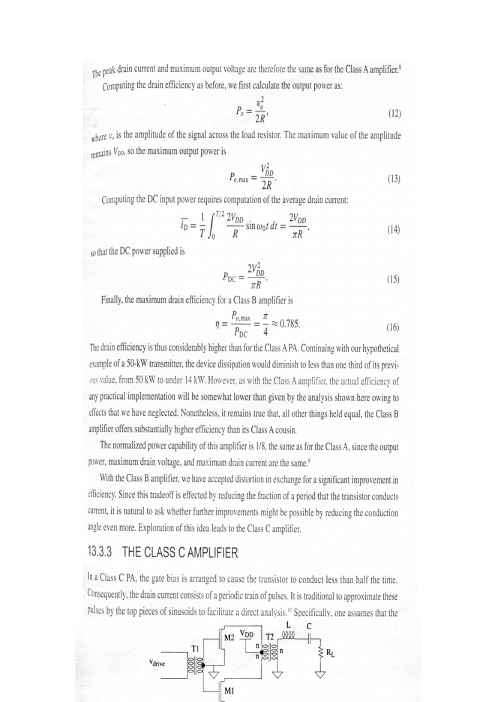
13.3.3 C类放大器在C类功率放大器中,栅的偏压设成使晶体管在小于一半的时间内导通。
因此,漏极电流是由周期性的一串脉冲构成的。
传统上用正弦的上面部分来近似这些脉冲以便于进行直接分析②。
特别是我们假设漏极电流具有如下的形式:式中,偏置值I DC类似于线性放大器中的偏置电流,它对于C类放大器实际上是负值。
自然,整个漏极电流i D心总是为正或为零。
也就是说,漏极电流在晶体管导通时是一段正弦波,而在晶体管截止时为零。
我们继续假设晶体管在任何时候的工作情况都像是一个电流源(高输出阻抗)③。
由于我们仍然有一个高Q值的输出振荡回路,所以在负载两端的电压基本上保持为正弦,因此漏极电压和漏极电流如图13.4所示。
在以下的推导中,不必担心能否重复所有的这些细节。
正如我们将要看到的,我们如何设计这样的放大器与这些公式本身的含义有显著的不同,所以重点要放在所得到的一般结论而不是一些具体细节上。
我们从求解漏极电流不为零时总的导通角开始。
为了简化得到这一答案所需要的步骤,我们首先用余弦而不是正弦来重新写出漏极电流的表达式:显然,这样做没有任何改变,因为时间原点总是任选的。
在经过这样的修改之后,电流脉冲就如图13.5所示。
使电流等于零并求出总的导通角2中得到:我们现在可以计算平均漏极电流为:在用I DC的表达式替换后得到:我们将很快用这个表达式来推导效率作为导通角函数的公式。
我们需要的另一个量是传送到负载的功率的一般表达式。
正如与B类放大器一样由于高Q值的振荡回路而被简化,所以我们只需要计算傅里叶级数中的基波项:利用我们通过负载的基波电流的表达式,我们可以很容易地推导出最大输出电压摆幅的公式:上式允许我们求解用V DD表示的电流irf:峰值漏极电流为irf与偏置项的和为:上式可简化为:对于固定的输出电压,当脉冲宽度减小至零时,峰值漏极电流接近无穷大。
利用我们刚刚推导的公式可以很容易地计算出漏极效率为:当导通角缩小至零时,效率接近100%。
手动变速器基础外文文献翻译、中英文翻译、外文翻译

附录附录A 英语科技文献Manual Transmission BasicsIt's no secret that cars with manual transmissions are usually more fun to drive than their automatic-equipped counterparts. If you have even a passing interest in the act of driving, then chances are you also appreciate a fine-shifting manual gearbox. But how does a manual trans actually work? With our primer on automatics(or slushboxes, as detractors call them) available for your perusal, we thought it would be a good idea to provide a companion overview on manual trannies, too.A brief history lesson shows that manual transmissions preceded automatics by several decades. In fact, up until General Motors offered an automatic in 1938, all cars were of the shift-it-yourself variety. While it's logical for many types of today's vehicles to be equipped with an automatic -- such as a full-size sedan, SUV or pickup -- the fact remains that nothing is more of a thrill to drive than a tautly suspended sport sedan, sport coupe or two-seater equipped with a precise-shifting five- or six-speed gearbox. It's what makes cars such as a Corvette, Mustang, Miata or any BMW sedan or coupe some of the most fun-to-drive cars available today.We know which types of cars have manual trannies. Now let's take a look at how they work. From the most basic four-speed manual in a car from the '60s to the most high-tech six-speed in a car of today, the principles of a manual gearbox are the same. The driver must shift from gear to gear. Normally, a manual transmission bolts to a clutch housing (or bell housing) that, in turn, bolts to the back of the engine. If the vehicle has front-wheel drive, the transmission still attaches to the engine in a similar fashion but is usually referred to as a transaxle. This is because the transmission, differential and drive axles are one complete unit. In a front-wheel-drive car, the transmission also serves as part of the front axle for the front wheels. In the remaining text, a transmission and transaxle will both be referred to using the term transmission.The function of any transmission is transferring engine power to the driveshaft and rear wheels (or axle halfshafts and front wheels in a front-wheel-drive vehicle). Gears inside the transmission change the vehicle's drive-wheel speed and torque in relation to engine speed and torque. Lower (numerically higher) gear ratios serve as torque multipliers and help the engine to develop enough power to accelerate from a standstill.Initially, power and torque from the engine comes into the front of the transmission and rotates the main drive gear (or input shaft), which meshes with the cluster or counter shaft gear -- a series of gears forged into one piece that resembles a cluster of gears. The cluster-gear assembly rotates any time the clutch is engaged to a running engine, whether or not the transmission is in gear or in neutral.There are two basic types of manual transmissions. The sliding-gear type and the constant-mesh design. With the basic -- and now obsolete -- sliding-gear type, nothing is turning inside the transmission case except the main drive gear and cluster gear when the trans is in neutral. In order to mesh the gears and apply engine power to move the vehicle, the driver presses the clutch pedal and moves the shifter handle, which in turn moves the shift linkage and forks to slide a gear along the mainshaft, which is mounted directly above the cluster. Once the gears are meshed, the clutch pedal is released and the engine's power is sent to the drive wheels. There can be several gears on the mainshaft of different diameters and tooth counts, and the transmission shift linkage is designed so the driver has to unmesh one gear before being able to mesh another. With these older transmissions, gear clash is a problem because the gears are all rotating at different speeds.All modern transmissions are of the constant-mesh type, which still uses a similar gear arrangement as the sliding-gear type. However, all the mainshaft gears are in constant mesh with the cluster gears. This is possible because the gears on the mainshaft are not splined to the shaft, but are free to rotate on it. With a constant-mesh gearbox, the main drive gear, cluster gear and all the mainshaft gears are always turning, even when the transmission is in neutral.Alongside each gear on the mainshaft is a dog clutch, with a hub that's positively splined to the shaft and an outer ring that can slide over against each gear. Both the mainshaft gear and the ring of the dog clutch have a row of teeth. Moving the shift linkagemoves the dog clutch against the adjacent mainshaft gear, causing the teeth to interlock and solidly lock the gear to the mainshaft.To prevent gears from grinding or clashing during engagement, a constant-mesh, fully "synchronized" manual transmission is equipped with synchronizers. A synchronizer typically consists of an inner-splined hub, an outer sleeve, shifter plates, lock rings (or springs) and blocking rings. The hub is splined onto the mainshaft between a pair of main drive gears. Held in place by the lock rings, the shifter plates position the sleeve over the hub while also holding the floating blocking rings in proper alignment.That's the basics on the inner workings of a manual transmission. As for advances, they have been extensive over the years, mainly in the area of additional gears. Back in the '60s, four-speeds were common in American and European performance cars. Most of these transmissions had 1:1 final-drive ratios with no overdrives. Today, overdriven five-speeds are standard on practically all passenger cars available with a manual gearbox.Overdrive is an arrangement of gearing that provides more revolutions of the driven shaft (the driveshaft going to the wheels) than the driving shaft (crankshaft of the engine). For example, a transmission with a fourth-gear ratio of 1:1 and a fifth-gear ratio of 0.70:1 will reduce engine rpm by 30 percent, while the vehicle maintains the same road speed. Thus, fuel efficiency will improve and engine wear will be notably reduced. Today, six-speed transmissions are becoming more and more common. One of the first cars sold in America with a six-speed was the '89 Corvette. Designed by Chevrolet and Zahnradfabrik Friedrichshafen (ZF) and built by ZF in Germany, this tough-as-nails six-speed was available in the Corvette up to the conclusion of the '96 model year. Today, the Corvette uses a Tremec T56 six-speed mounted at the back of the car.Many cars are available today with six-speeds, including the Mazda Miata, Porsche Boxster S and 911, Dodge Viper, Mercedes-Benz SLK350, Honda S2000, BMW 3-Series and many others. Some of these gearboxes provide radical 50-percent (0.50:1) sixth-gear overdrives such as in the Viper and Corvette, while others provide tightly spaced gear ratios like in the S2000 and Miata for spirited backroad performance driving. While the bigger cars mentioned above such as the Viper and Vette often have two overdrive ratios (fifth and sixth) the smaller cars like the Celica and S2000 usually have one overdriven gear ratio (sixth) and fifth is 1:1.Clearly a slick-shifting manual transmission is one of the main components in a fun-to-drive car, along with a powerful engine, confidence-inspiring suspension and competent brakes. For more information on a manual transmission's primary partner component, check out our basic primer on clutches and clutch operation.附录B 文献翻译手动变速器基础汽车手动变速器相比于自动变速器的驾驶装备来说,在驾驶方面拥有更多的乐趣,这已不再是什么秘密了。
科技文献翻译
科技文献翻译Technology has transformed every aspect of our lives, from the way we communicate and work to how we shop and entertain ourselves. With the rapid advancement of technology, there is a growing demand for accurate translations of technology-related literature. This article aims to provide a translation of a technology paper consisting of 700 words.The paper titled "The Role of Artificial Intelligence in Autonomous Vehicles" explores the impact of AI in self-driving cars. Autonomous vehicles have gained significant attention in recent years due to their potential to revolutionize transportation. This paper discusses how AI technologies, such as deep learning and machine vision, have contributed to the development of autonomous vehicles.一项名为“人工智能在自动驾驶汽车中的角色”的研究探讨了AI在无人驾驶汽车中的影响。
在过去几年中,由于其改变出行方式的潜力,自动驾驶汽车引起了广泛关注。
英文文献科技类天线的性能原文及翻译

目录1 天线的性能 (1)1.1天线辐射 (2)1.2增益 (3)1.3有效面积 (6)1.4路径损耗 (6)1.5雷达距离方程和截面 (8)1.6为什么要使用一个天线? (10)2 PROPERTIES OF ANTENNAS (11)2.1 ANTENNA RADIATION (12)2.2GAIN (14)2.3EFFECTIVE AREA (17)2.4PATH LOSS (17)2.5RADAR RANGE EQUATION AND CROSS SECTION (19)2.6WHY USE AN ANTENNA? (22)1 天线的性能一个方法是一本有关天线的书是从讨论天线如何辐射开始的。
从麦克斯韦方程组,我们得出了电磁波。
之后,进行冗长的讨论,其中包含了很多数学,我们在讨论这些波如何在导体上激发电流。
这个情节的下半部分,就是电流的辐射和产生的电磁波。
你可能已经研究过这个问题,或如果你想增进你的阅历,参考在电磁学方面的书籍。
研究电磁学就有了一些数学方面的见识来描述天线的辐射,并提供严谨,以防止错误。
我们跳过讨论这些方程,直接转到实际的问题。
这是很重要的认识到,天线在电流中产生辐射。
设计构成的控制电流产生预期的辐射分布,其所谓的方向图。
在许多情况下,问题是如何防止电流中的辐射,如在集成电路。
每当一电流变为在距离上从其返回电流中分隔,它发热着。
简单地说,我们的设计就是为了保持两个电流靠近在一起,以减少辐射。
一些讨论会忽略电流的分布,而作为代替则会考虑得出的数量,如在各个领域的光圈或磁流在一个缝隙或靠近边缘的一微带斑纹。
你会发现我们使用任何的概念来提供深入的或简化的数学。
天线1转换电路领域,必将成为传播的电磁波,并通过互惠,从通过电磁波中收集动力。
麦克斯韦方程组预测,任何时间变电气或磁场产生相反的领域和形成一电磁波。
波有其两个领域的面向正交,而且它在正常的方向上传播给由垂直的电场和磁场所定的飞机。
- 1、下载文档前请自行甄别文档内容的完整性,平台不提供额外的编辑、内容补充、找答案等附加服务。
- 2、"仅部分预览"的文档,不可在线预览部分如存在完整性等问题,可反馈申请退款(可完整预览的文档不适用该条件!)。
- 3、如文档侵犯您的权益,请联系客服反馈,我们会尽快为您处理(人工客服工作时间:9:00-18:30)。
外文翻译DC GENENRATORS1. INTRODUCTIONFor all practical purposes, the direct-current generator is only used for special applications and local dc power generation. This limitation is due to the commutator required to rectify the internal generated ac voltage, thereby making largescale dc power generators not feasible.Consequently, all electrical energy produced commercially is generated and distributed in the form of three-phase ac power. The use of solid state converters nowadays makes conversion to dc economical. However, the operating characteristics of dc generators are still important, because most concepts can be applied to all other machines.2. FIELD WINDING CONNECTIONSThe general arrangement of brushes and field winding for a four-pole machine is as shown in Fig.1. The four brushes ride on the commutator. The positive brusher are connected to terminal A1 while the negative brushes are connected to terminal A2 of the machine. As indicated in the sketch, the brushes are positioned approximately midway under the poles. They make contact with coils that have little or no EMF induced in them, since their sides are situated between poles.Figure 1 Sketch of four-pole dc matchineThe four excitation or field poles are usually joined in series and their ends brought out to terminals marked F1 and F2. They are connected such that they produce north and south poles alternately.The type of dc generator is characterized by the manner in which the fieldexcitation is provided. In general, the method employed to connect the field and armature windings falls into the following groups (see Fig.2):Figure2 Field connections for dc generators:(a)separately excited generator;(b)self-excited,shunt generator;(c)series generator;(d)compound generator;short-shunt connection;(e)compoundgenerator,long-shunt connection.The shunt field contains many turns of relatively fine wire and carries a comparatively small current, only a few percent of rated current. The series field winding, on the other hand, has few turns of heavy wire since it is in series with the armature and therefore carries the load current.Before discussing the dc generator terminal characteristics, let us examine the relationship between the generated voltage and excitation current of a generator on no load. The generated EMF is proportional to both the flux per pole and the speed at which the generator is driven, EG=kn. By holding the speed constant it can be shown the EG depends directly on the flux. To test this dependency on actual generators is not very practical, as it involves a magnetic flux measurement. The flux is produced by the ampere-turns of the field coils: in turn, the flux must depend on the amount of field current flowing since the number of turns on the field winding is constant. This relationship is not linear because of magnetic saturation after the field current reaches a certain value. The variation of EG versus the field current If may be shown by a curve known as the magnetization curve or open-circuit characteristic. For this a given generator is driven at a constant speed, is not delivering load current, and has its fieldwinding separately excited.The value of EG appearing at the machine terminals is measured as If is progressively increased from zero to a value well above rated voltage of that machine. The resulting curve is shown is Fig.3. When Ij=0, that is, with the field circuit open circuited, a small voltage Et is measured, due to residual magnetism. As the field current increases, the generated EMF increases linearly up to the knee of the magnetization curve. Beyond this point, increasing the field current still further causes saturation of the magnetic structure to set in.Figure 3 Magnetization curve or open-circuit characteristic of a separately excited dc machine The means that a larger increase in field current is required to produce a given increase in voltage.Since the generated voltage EG is also directly proportional to the speed, a magnetization curve can be drawn for any other speed once the curve is determined. This merely requires an adjustment of all points on the curve according ton n x E E G G ''where the quantities values at the various speeds.3. VOLTAGE REGULATIONLet us next consider adding a load on generator. The terminal voltage will then decrease (because the armature winding ha resistance) unless some provision is made to keep it constant. A curve that shows the value of terminal voltage for various load currents is called the load or characteristic of the generator.Figure 4 (a) directs current it to urge the generator load characteristics; (b) circuit diagramFig.4 shows the external characteristic of a separately excited generator. The decrease in the terminal voltage is due mainly to the armature circuit resistance RA. In general,A A G t R I E V -=where Vt is the terminal voltage and IA is the armature current (or load current IL) supplied by the generator to the load.Another factor that contributes to the decrease in terminal voltage is the decrease in flux due to armature reaction. The armature current established an MMF that distorts the main flux, resulting in a weakened flux, especially in noninterpole machines. This effect is called armature reaction. As Fig.4 shows, the terminal voltage versus load current curve does not drop off linearly since the iron behaves nonlinear. Because armature reaction depends on the armature current it gives the curve its drooping characteristic.4. SHUNT OR SELF-EXCIITED GENRATORSA shunt generator has its shunt field winding connected in parallel with the armature so that the machine provides its own excitation, as indicated in Fig.5. The question arises whether the machine will generate a voltage and what determines the voltage.For voltage to “build up ” as it is called, there must be some remanent magnetism in the field poles. Ordinarily, if the generator has been used previously, there will be some remanent magnetism. We have seen in Section 3 that if the field would be disconnected, there will be small voltage Ef generated due to this remanent magnetism, provided that the generator is driven at some speed. Connecting the field for self-excitation, this small voltage will be applied to the shunts field and drive a small current through the field circuit. If this resulting small current in the shunt field is of such a direction that it weakens the residual flux, the voltage remains near zeroand the terminal voltage does not build up. In this situation the weak main pole flux opposes the residual flux.Figure 5 Shunt generator:(a)circuit;(b)load characteristicIf the connection is such that the weak main pole flux aids the residual flux, the induced voltage increases rapidly to a large, constant value. The build-up process is readily seen to be cumulanve. That is, more voltage increases the field current, which in turn increases the voltage, and so on. The fact that this process terminates at a finite voltage is due to the nonlinear behavior of the magnctic circuit. In steady state the generated voltage is causes a field current to flow that is just sufficient to develop a flux required for the generated EMF that causes the field current to flow.The circuit carries only dc current, so that the field current depends only on the field circuit resistance, Rf. This may consist of the field circuit resistance Rf, the field current depends on the generated voltage in accordance with Ohm ’s law.It should be evident that on a new machine or one that has lost its residual flux because of a long idle period, some magnetism must be created. This is usually done by connecting the field winding only to a separate dc source for a few seconds. This procedure is generally known as flashing the field.Series GeneratorsAs mentioned previously, the field winding of a series generator is in series with the armature. Since it carries the load current the series field winding consists of only a few turns of thick wire. At no load, the generated voltage is small due to residual field flux only. When a load is added, the flux increases, and so does the generated voltage. Fig.7 shows the load characteristic of a series generator driven at a certain speed. The dashed line indicates the generated EMF of the same machine with the armature open-circuited and the field separately excited. The difference between the two curves is simply the IR drop in the series field and armature winding, such that)(S A A G t R R I E V +-=where RS is the series field winding resistance.Figure 7 Series generator: (a)circuit diagram;(b)load characteristicsCompound Generators The compound generator has both a shunt and a series field winding, the latter winding wound on top of the shunt winding. Fig.8 shows the circuit diagram. The two windings are usually connected such that their ampere-turns act in the same direction. As such the generator is said to be cumulatively compounded.The shunt connection illustrated in Fig.8 is called a long shunt connection. If the shunt field winding is directly connected across the armature terminals, the connection is referred to as a short shunt. In practice the connection used is of little consequence, since the shunt field winding carries a small current compared to the full-load current. Furthermore, the number of turns on the series field winding. This implies it has a low resistance value and the corresponding voltage drop across it at full load is minimal.Curves in Fig.9 represents the terminal characteristic of the shunt field winding alone. By the addition of a small series field winding the drop in terminal voltage with increased loading is reduced as indicated. Such a generator is said to be undercompounded. By increasing the number of series turns, the no-load and full-load terminal voltage can be made equal; the generator is then said to be flatcompounded. If the number of series turns is more than necessary to compensate for the voltage drop, the generator is overcome pounded. In that case the full-load voltage is higher than the no-load voltage.Figure 9 Terminal characteristics of compound generators compared with that of the shunt generatorThe overcompounded generator may be used in instances where the load is at some distance from the generator. The voltage drops in the feeder lines are the compensated for with increased loading. Reversing the polarity of the series field in relation to the shunt field, the fields will oppose each other more and more as the load current increase. Such a generator is said to be differentially compounded. It is used in applications where feeder lines could occur approaching those of a short circuit. An example would be where feeder lines could break and short circuit the generator. The short-circuit current, however, is then limited to a “safe”value. The terminal characteristic for this type of generator is also shown in Fig.9. Compound generators are used more extensively than the other types because they may be designed to have a wide varity of terminal characteristics.As illustrated, the full-load terminal voltage can be maintained at the no-load value by the proper degree of compounding. Other methods of voltage control are the use of rheostats, for instance, in the field circuit. However, with changing loads it requires a constant adjustment of the field rheostat to maintain the voltage. A more useful arrangement, which is now common practice, is to use an automatic voltage regulator with the generator. In essence, the voltage regulator is a feedback control system. The generator output voltage is sensed and compared to a fixed reference voltage deviation from the reference voltage gives an error signal that is fed to a power amplifier. The power amplifier supplies the field excitation current. If the error signal is positive, for example, the output voltage is larger than desired and the amplifier will reduce its current drive. In doing so the error signal will be reduced to zero.中文翻译直流发电机1.介绍对于所有实际目的来说,直流发电机仅用于特殊场合和地方性发电厂。