ISO26262 开发接口协议DIA
iso26262标准各章节具体内容
ISO xxx是国际上广泛认可的汽车电子系统安全标准,它对汽车电子系统的设计、开发和生产提出了严格的要求和规范。
ISO xxx标准共分为12个章节,每个章节都涵盖了汽车电子系统安全的关键方面。
下面,我将对ISO xxx标准的各章节具体内容进行全面评估并撰写一篇有价值的文章,希望能够帮助你更深入地理解ISO xxx标准。
1. 概述 ISO xxx标准的概述部分主要介绍了该标准的出台背景、范围和目的,以及对术语和定义进行了详细解释。
在概述部分,标准对汽车电子系统安全的重要性进行了阐述,指出了汽车电子系统安全的挑战和风险,为后续章节的内容提供了重要的背景铺垫。
2. 术语和定义第二章节主要对ISO xxx标准中所涉及的术语和定义进行了详细的解释和说明。
这对于标准的理解和运用起到了重要的作用,也为后续的章节内容提供了必要的概念基础。
**3. 管理*/ 第三章节是关于汽车电子系统安全管理的内容,主要包括了安全管理的责任和任务分配、安全管理计划的制定和执行、安全管理过程的控制和监督等内容。
在这一章节中,标准提出了对于汽车电子系统安全管理的严格要求,要求相关的责任人员必须具备专业的知识和经验,以确保汽车电子系统的安全管理得到有效执行。
**4. 安全计划项的内容和要求*/ 第四章节主要包括了对汽车电子系统安全计划的内容和要求的详细阐述。
安全计划是确保汽车电子系统从设计到生产都符合ISO xxx标准要求的关键部分,标准对安全计划的编制、实施和审核提出了明确的要求,并对安全计划的内容进行了详细的列举和解释。
**5. 扩展性依赖性和适用性*/ 第五章节主要讨论了ISO xxx标准的扩展性依赖性和适用性。
在这一章节中,标准指出了在特定的情况下,对标准的适用性可能会有所不同,因此需要根据具体情况进行灵活的解释和应用。
这一章节的内容对于理解和正确应用ISO xxx标准具有重要的指导意义。
**6. 安全管理过程*/ 第六章节是关于汽车电子系统安全管理过程的内容,主要包括了安全需求的确定、安全分析和评估、功能安全验证和确认等内容。
ISO26262 开发接口协议DIA
Development Interface Agreement
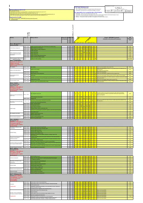
INSTRUCTIONS FOR COMPLETION For each Work Product: - SUPPLIER shall confirm the responsibility in completing Work Products (Col. Q, R, S, T) - SUPPLIER shall confirmthe Work Product submission level (Col. V) - SUPPLIER shall state all the document references covering the WP for the concerned EE component (Col. U) - SUPPLIER documents submission content shall comply with the DCI when existing (Col. G) Requirement level for ASIL ++: Highly recommended : SUPPLIER should provide document
WP
Submission level
R
A
a
S
I X X X
R X X X X
A X X X X X X X X
S
I Full Full Full Full Full Full Full Full X Consultation
iso26262功能安全评价方法
iso26262功能安全评价方法【原创实用版2篇】目录(篇1)1.Iso26262 功能安全评价方法的背景和意义2.Iso26262 功能安全评价方法的具体内容3.Iso26262 功能安全评价方法的实施步骤4.Iso26262 功能安全评价方法的优势和应用5.Iso26262 功能安全评价方法的未来发展正文(篇1)一、Iso26262 功能安全评价方法的背景和意义Iso26262 功能安全评价方法是一种针对汽车电子系统功能安全的国际标准,它的出现是为了确保汽车电子系统在失效情况下能够按照预期方式进行故障处理,从而避免对人员和环境造成伤害。
随着汽车电子化程度的不断提高,功能安全日益受到重视,Iso26262 功能安全评价方法应运而生,成为了保证汽车安全的重要手段。
二、Iso26262 功能安全评价方法的具体内容Iso26262 功能安全评价方法主要包括以下几个方面:1.安全目标的定义:根据汽车电子系统的功能和失效模式,明确安全目标,确保系统在失效情况下能够按照预期方式进行故障处理。
2.危害分析:通过对汽车电子系统可能的失效模式进行分析,评估可能带来的风险和危害程度。
3.功能安全等级:根据危害分析结果,为汽车电子系统中的各个功能分配相应的安全等级。
4.安全要求和措施:针对不同安全等级的功能,制定相应的安全要求和措施,确保系统在失效情况下能够满足安全目标。
5.验证和评估:对汽车电子系统进行实际验证和评估,检查系统在失效情况下是否能够按照预期方式进行故障处理。
三、Iso26262 功能安全评价方法的实施步骤1.建立项目团队:由汽车制造商、零部件供应商、技术服务公司等相关方共同组成项目团队,明确各方职责和任务。
2.收集和分析相关信息:收集汽车电子系统的设计、制造、使用等方面的信息,进行系统分析和失效模式分析。
3.制定安全目标和功能安全等级:根据分析结果,制定安全目标和功能安全等级。
4.制定和实施安全要求和措施:针对不同安全等级的功能,制定相应的安全要求和措施,并确保在系统设计和制造过程中得到有效实施。
ISO 26262功能安全相关的特殊图形符号和AIAG APQP参考手册与全球供应商质量指南(G-S
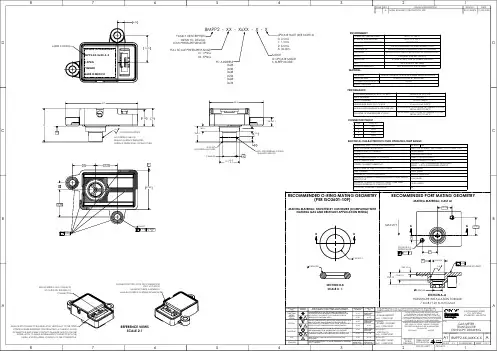
A CHARACTERISTIC OF AN ITEM, ELEMENT OR PRODUCTION PROCESS FOR WHICH REASONABLY FORESEEABLE DEVIATION COULD AFFECT, CONTRIBUTE TO OR CAUSE ANY POTENTIAL REDUCTION OF FUNCTIONAL SAFETY.COMPLIANCEMONITORING OFREQUIREDCOMPLIANCEMONITORING OFREQUIREDMONITORING OFREQUIREDCOMPLIANCEFIRST ARTICLE INSPECTION/OK FIRST PART≥ 1.33≥ 1.33≥ 1.67≥ 1.67≥ 1.67≥ 1.67≥ 1.67≥ 1.67≥ 1.67≥ 1.67OK FIRST PARTINSPECTION/FIRST ARTICLENON-KEY CHARACTERISTIC - STANDARD DIMENSION VS. STANDARD (INCL. TOLERANCE)USED TO SPECIFY ONGOING SPC METHODOLOGIES TO BE PERFORMED.SIGNIFICANT CHARACTERISTICS ARE THOSE PRODUCT PARAMETERS AND REQUIREMENTS THAT ARE IMPORTANT FOR CUSTOMERSATISFACTION (FORM, FIT AND FUNCTION) AND FOR WHICH QUALITY PLANNING ACTIONS MUST BE ADDRESSED ON A CONTROL PLAN.CRITICALSIGNIFICANTSPC (INITIAL) SHORT TERM Cpk≥ 1.67ISO 26262FUNCTIONAL SAFETY RELATED SPECIALDRAWING SYMBOLAIAG APQP REFERENCE MANUAL, GLOBAL SUPPLIER QUALITY MANUAL (G-SM-01) QMS-1004255, APPENDIX ALONG TERMPpk STANDARDSSSSCHARACTERISTICNAME CONTROL ITEM PRODUCTS HAVE CRITICAL CHARACTERISTICS THAT MAY AFFECT SAFE VEHICLE/PRODUCT OPERATION AND/ORCOMPLIANCE WITH GOVERNMENT REGULATIONS. UNIQUE SYMBOLS IDENTIFYING SAFETY AND REGULATORY CHARACTERISTICS.REFERENCE VIEWSSCALE 2:1SINGLE SIDED GOLD CONTACTSLOCATED ON THIS SIDE OFCONNECTORALWAYS LIFT CONNECTOR SLIDER LATCH VERTICALLY TO THE OPEN POSITION WHEN INSERTING OR EXTRACTING A CABLE TO AVOID CONNECTOR AND CABLE CONTACT DAMAGE. MUST CLOSE THESLIDER LATCH TO MAKE A PERMANENT CONNECTION TO THECABLE. AVOID LATERAL LOADING OF THE CONNECTOR.CONNECTOR TYPE: 4 POS FFC CONNECTORPIN 1 LOCATIONMANUFACTURER: AMPHENOLMANUFACTURER P/N: SFW4S-2STMAE1LF1940.79.35100.4ON PISTON SURFACENO PARTING LINE ONSEALING SURFACE PERMITTEDSURFACE FINISH SPI-B1 OR SMOOTHERA0.3 X 59°NO BURRS ALLOWED31.53±0.19±0.12X 5±0.130.411.5+-0.20.17.86±0.05ISO-109 EXTERNAL O-RING SEALING SURFACEB1312.25415.253.6±0.122.450.2A B C0.05C15.254(2X) M3 X 0.5 TAPPED HOLE1312.25AAGRAVITY0.1A12±0.05 2±0.10 6.5±0.1010±0.108.32±0.05SECTION A-A0.4.08UNDER SENSOR HOUSINGA15.254.03SENSATA TECHNOLOGIES 8MPP2-XX-XxXX-X-X X-XPSIG YYMMDD MADE IN MEXICOLASER CODING7.59±0.13BB2.62±0.08SECTION B-B SCALE 4 : 1MATERIALPERFORMANCEENVIRONMENTELECTRICAL CHARACTERISTICS OVER OPERATING TEMP RANGERECOMMENDED PORT MATING GEOMETRYMATING MATERIAL: CAST AlHARDWARE INSTALLATION TORQUE:7 IN-LB (1.20 N-mm) MAXCONNECTOR PINOUTUPDATE RATE (SEE NOTE 3)0: 0.5ms 1: 1.5ms 2: 6.5ms 3: 32.0ms I²C ADDRESS0x280x380x480x580x680x78MODEU: UPDATE MODE S: SLEEP MODEFULL SCALE PRESSURE RANGE01: 1PSIG 05: 5PSIGFAMILY DESCRIPTION MEMS I²C DIGITAL LOW PRESSURE SENSOR8MPP2 - XX - XxXX - X - XRECOMMENDED O-RING MATING GEOMETRY(PER ISO3601-109)MATING MATERIAL: SELECTED BY CUSTOMER (COMPATIBLE WITHNATURAL GAS AND RELEVANT APPLICATION MEDIA)PACKAGEBLACK FORTRON 1140 L4 (40% FIBER REINFORCED PPS)PRESSURE SEALO-RING SUPPLIED BY END USERCONNECTOR CONTACTS GOLDRoHS COMPLIANTPIN OUTPUT 1SCL 2SDA 3VSUP 4GNDOPERATING TEMPERATURE -40°C TO +85°C STORAGE TEMPERATURE -40°C TO +125°C FULL SCALE PRESSURE RANGE TRUE GAGEHUMIDITY 95% CONDENSING ON ATMOSPHERIC PORT ORIENTATION SENSING ELEMENT PERPENDICULAR TO GROUND EXPOSURE NATURAL GAS AND ITS IMPURITIES ON GAS SIDE PORTSHOCK 100G/6ms (PER MIL-STD-810)VIBRATION 5-150Hz @ 5m/s² FOR 20 SWEEPS PER AXISESDIEC 61000-4-2; 2kV HBM RADIATED IMMUNITYIEC 61000-4-20; 50V/m LEVELTOTAL ERROR BAND @ -40°C TO 85°C ±2.0%FSP @ Vs = 3.3VBURST PRESSURE70 PSIGPROOF PRESSURE20 PSIG (MAX)HELIUM LEAK RATE, OUT OF BOX <1e-6 cc/sec @25°CNATURAL GAS LEAKAGE RATE OVER LIFE <0.1mL/min @ 10 PSI AFTER 1k THERMAL CYCLESFROM -40°C TO 85°CTEB AFTER 1k TEMPERATURE CYCLES±2.0% @Vss = 3.3V AFTER 1k THERMAL CYCLESFROM -40°C TO 85°COPERATING SUPPLY VOLTAGE RANGE (Vs) 3.3 VDC 5%INPUT VOLTAGE PROTECTION VSUP: -0.3 TO 6VDC; ALL OTHERS: -0.3 TO VSUP + 0.3AVERAGE SUPPLY CURRENT 2.5mA (MAX)OUTPUT14 BIT DIGITAL OUTPUT OUTPUT RANGE (0%FSP TO 100%FSP)1638 TO 14745 COUNTS OUTPUT RESOLUTION12 BITS SCALED TO 14 BITSPOWER ON RESET THRESHOLDFALLING - 1.8V GUARANTEED SHUTDOWN RISING - 2.35V GUARANTEED STARTUP MAX POWER UP TIME TO OUTPUT VALID 8.4ms (MAX)PEAK CURRENT10mA (MAX)Vs RAMP UP TO 3.3V TIME LIMITS5µS MIN, 20µS MAX AVERAGE CURRENT DURING A POWER UP AND SINGLE READ CYCLE2mA (MAX)AVERAGE CURRENT DURING I²C READ OVER TEMP (DURING INTERVAL I²C START TO STOP) 2.5mA (MAX)VOLTAGE (Vs) NOISE TOLERANCE5%SHEET 1 OF 28MPP2-XX-XxXX-X-XAGAS METER TRANSDUCER ENVELOPE DRAWINGADEVICE: 8MPPPROJECT:DATE ECN NO.REVISION DESCRIPTIONTOLERANCESDECIMALS ANGLESINTERPRET DIMENSIONING AND TOLERANCING PER ASME Y14.5-2009. UNLESS OTHERWISE SPECIFIED DIMENSIONS ARE IN MILLIMETERS.FOR REFERENCE ONLY, CHECK LATEST REVISION BEFORE USE.PARTS MADE TO THIS PRINT MUST CONFORM TO E9898 REV. E.REV.AINITIAL RELEASE TO PRODUCTION; RTBECO-38827510-SEP-20208ZONE REV.TITLEDWG NO.SCALE3:1ROB BALLERSTEDT ENGINEER DATE 10-SEP-2020THIRD ANGLE PROJECTION SOLIDWORKSDATE DRAWN DATE DATE APPROVED APPROVEDROBERT LOUGHREY MIKE FALCO 10-SEP-202010-SEP-2020RICARDO YANEZ 10-SEP-2020529 PLEASANT STREETP.O. BOX 2964ATTLEBORO, MA 02703SIZEA1SENSATA TECHNOLOGIES PROPRIETARY AND CONFIDENTIAL. NEITHER THIS PRINT NOR THE INFORMATION CONTAINED HEREON IS TO BE USED AGAINST THE INTERESTS OF SENSATA TECHNOLOGIES OR AGAINST THE INTERESTS OF ANY OF ITS AFFILIATED COMPANIES OR WHOLLY OWNED SUBSIDIARIES.DO NOT SCALE DRAWINGBCDABDC765432158763142R0.4 REF 5±0.1001±0.050 PITCH (GOLD PLATED CONTACTS)0.700±0.0800.33±0.05 I²C COMMUNICATION:DEVICE SLAVE WAIT FOR PRESSURE MASTER PRESSURE MASTER ADDRESS [6:0] SLAVE ACK DATA [13:8] ACK DATA [7:0] NACK NOTE: THERE ARE THREE ADJUSTMENTS TO THE I²C IMPLEMENTATION COMPARED WITH THE ORIGINAL I²C PROTOCOL:NO EXTERNAL CAPACITANCE NEEDED FOR Vs5.RECOMMENDED CABLE GEOMETRYSENDING A START-STOP CONDITION WITHOUT ANY TRANSITIONS ON THE CLK LINE (NO CLOCK•PULSES IN BETWEEN) CREATES A COMMUNICATION ERROR FOR THE NEXT COMMUNICATION,EVEN IF THE NEXT START CONDITION IS CORRECT AND THE CLOCK PULSE IS APPLIED. ANSHEET 2 OF 28MPP2-XX-XxXX-X-X A REV.DWG NO.20:1SOLIDWORKS529 PLEASANT STREETP.O. BOX 2964ATTLEBORO, MA 02703。
5.5-相关技术---功能安全法规ISO26262简介

ISO26262
形式认证法规ECER79(转向)包含对功能安全的基本要求。北 美的OEM和供应商已经加快了追赶欧洲的步伐,正在依照ISO26262 建立自己IDE功能安全体系,SAE组织(美国机动车工程师协会)已 经组件汽车功能安全委员会(AFSC:Automotive Functional safety committee)在为欧洲OEM提供产品的一级供应商的驱动下,日本 在2010年末至2011年初,主流OEM启动了对ISO26262合规进程的启 动会议,由JAMA(一般社团法人日本自动车工业会)和JARI(日本自 动车研究所)合作创建通用的工作流程。国内的OEM和一级供应商 也非常关注ISO26262的动态,国标的转化工作正在中国汽车技术研 究中心的指导下全面展开
参考文献:电动助力转向系统故障诊断与失效保护 作者:张 瑞 硕士论文 2014.10 中国科学技术大学
故障诊断技术
系统故障自诊断是指系统的自身的硬件设计或者程序对系统 正常工作状态和工作异常作出判断,并根据故障特征,诊断系统故 障通过失效保护及处理程序,准确的定位故障。根据不同的故障类 型,使系统进入到安全的工作模式。
故障诊断技术
• 故障自诊断系统的主要任务有以下几块:系统对系统自身的故障 探测、诊断系统对故障类别的判断、系统故障定位及系统故障失 效保护等等。故障探测定义为系统正常工作后,通过周期性地实 时监测系统的运行状态,并通过系统设计好的诊断条件,判断系 统有没有产生了故障;诊断系统对故障类别的判断就是故障自诊 断系统在检测出故障发生后,自动告知系统故障的模式;故障定 位认为在故障自诊断系统监测出系统工作异常,并已经进行了系 统故障类别的判断,按照系统预定义的诊断条件定义具体故障位 置并记录故障诊断条件参数。同时,为系统的失效保护提供输入 信息;故障失效保护是系统故障诊断过程中最后一个环节,同时 也是最重要的一个环节,使系统能够根据故障原因,采取不同的 保护措施。
功能安全FunctionalSafetyISO26262-1
功能安全FunctionalSafetyISO26262-1ISO 26262-1 词汇表ISO26262是基于IEC61508标准演化⽽来的⼀项标准,旨在满⾜道路车辆电⼦电⽓系统领域的特定需求。
这种改编适⽤于由电⼦电⽓元件和软件组件组成的安全系统的整个⽣命周期内的所有活动。
安全是未来汽车发展的关键问题之⼀。
⼀些新的功能,在驾驶员辅助、动⼒、车内动态控制和主动&被动安全系统等⽅⾯⽇益牵涉到越来越多的系统安全⼯程。
这些功能的开发和集成会增加对安全系统开发流程、并证明所有合理的系统安全⽬标都得到满⾜的证据的需求程度。
随着技术复杂度、软件内容和机电⼀体化程度的不断提⾼,系统失效和随机硬件失效的风险也越来越⼤。
ISO 26262会提供适当的要求和流程来避免这些风险。
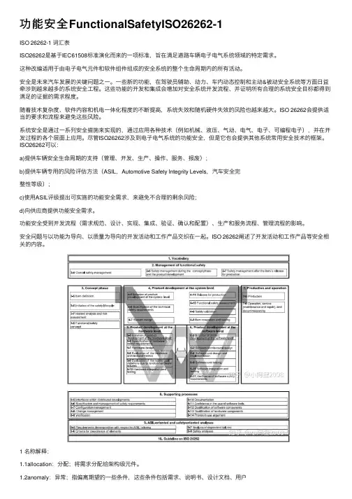
系统安全是通过⼀系列安全措施来实现的,通过应⽤各种技术(例如机械、液压、⽓动、电⽓、电⼦、可编程电⼦),并在开发过程的各个层⾯上应⽤。
尽管ISO26262涉及到电⼦电⽓系统的功能安全,但是它也会提供其他系统常⽤安全技术的框架。
ISO26262可以:a)提供车辆安全⽣命周期的⽀持(管理、开发、⽣产、操作、服务、报废);b)提供车辆专⽤的风险评估⽅法(ASIL,Automotive Safety Integrity Levels,汽车安全完整性等级);c)使⽤ASIL评级提出可实施的功能安全需求,来避免不合理的剩余风险;d)向供应商提供功能安全需求。
功能安全受到开发流程(需求规范、设计、实现、集成、验证、确认和配置)、⽣产和服务流程、管理流程的影响。
安全问题与以功能为导向、以质量为导向的开发活动和⼯作产品交织在⼀起。
ISO 26262阐述了开发活动和⼯作产品等安全相关的内容。
1 名称解释:⽂档、标准或者经验。
1.3architecture:架构;代表相关项/功能/系统/元件的构造块及构造块的边界和接⼝,且相关的功能已经分配给了硬件/软件元件。
汽车功能安全ISO26262 ASIL分解经验
17 February 2011
A HW/SW element inherits the ASIL from the highest ASIL function running on it
Experience with ASIL Decomposition
3
Lowering the ASIL
• In this case, the ASIL associated with the hardware or software component is inherited from the function with the highest ASIL
Function 1 (ASIL x) Function 2 (ASIL y)
7
Industrial Scenario
17 February 2011
Experience with ASIL Decomposition
8
Problem Description
• Consider a function F which, upon input from a combination of sensors S1, S2, ... Sn issues an activation command to actuator M (“Motor”)
4
Valid Combinations
Table of valid combinations for ASIL decomposition
17 February 2011
Experience with ASIL Decomposition
5
ASIL Decomposition Basics
ISO26262_DIA模板
eate validation plan 6 Specification of the technical safety requirements
Derive technical safety requirements Verify technical safety requirements Refine validation plan 7 System design
Refine software safety requirements Perform safety analysis (Check if required) Perform dependent failure analyses (Checkk if required) Verify software architecture 8 Software unit design and implementation Specify software units Implement software untis Perform static verification of implemented software units 9 Software unit testing Refine software verification plan Specfiy unit tests Perform unit test 10 Software integration and testing Plan software integration testing Specify software integration tests Perform software integration test 11 Verification of software safety requirements Plan verification of software safety requirements Specify software safety requirements verification tests Perform software safety requirements verification test 12 Annex C Configuration Specify configuration data Specify calibration data Refine safety plan Create configuration data Create calibration data Refine software verification plan Specify tests of variants Perform test of configurations 7 Production
基于ISO 26262的新能源汽车电子电器部件功能安全开发简介
Automobile Parts 2021.06063Introduction to Functional Safety Development of Electronic Components for New Energy Vehicles Based on ISO 26262基于ISO 26262 的新能源汽车电子电器部件功能安全开发简介收稿日期:2021-03-01作者简介:辛强(1983 ),男,硕士,高级工程师,研究方向为发动机技术及新能源㊂E-mail:㊂DOI :10.19466/ki.1674-1986.2021.06.012基于ISO 26262的新能源汽车电子电器部件功能安全开发简介辛强1,朱卫兵2,胡璟1(1.中国汽车零部件工业有限公司,北京100083;2.上汽通用五菱汽车股份有限公司质量部,广西柳州545007)摘要:为加深理解并提高汽车电子电器部件的功能安全,介绍了功能安全的概念以及电子电器部件安全性的开发过程㊂分析了汽车安全完整性等级(ASIL 等级)评估分级,并通过实例进一步解释了功能安全等级的划分标准㊂基于ISO 26262标准,提出了一个新的汽车功能安全设计方案,并给出了每一个设计环节的注意事项和要求,为汽车电子电器部件功能安全设计开发者提供参考㊂关键词:功能安全;汽车电子电器部件;安全等级评估中图分类号:U463Introduction to Functional Safety Development of Electronic Componentsfor New Energy Vehicles Based on ISO 26262XIN Qiang 1,ZHU Weibing 2,HU Jing 1(1.China Auto Parts &Accessories Corp,Beijing 100083,China;2.SAIC-GM-Wuling Automobile Co.,Ltd.,Liuzhou Guangxi 545007,China)Abstract :In order to deeply understanding and improve the functional safety of automotive electronic and electrical components,theconcept of functional safety and the development process of the safety of electronic and electrical components were introduced.The assessmentclassification of ASIL level was analyzed,and the classification standard of functional safety level was further explained through an example.Based on ISO 26262standard,a new automotive functional safety design scheme was proposed,and the notes and requirements of each designlink were given,which provided a reference for the developers of functional safety design of automotive electronic and electrical components.Keywords :Functional safety;Automotive electronic and electrical components;ASIL level0㊀引言随着电子电器部件的集成度要求越来越高,面临的安全问题也越来越严重,如丰田汽车于2010年召回了几百万车辆,主要就是由于汽车电子油门踏板引起的故障㊂功能安全是指避免由系统功能性故障导致的不可接受的风险,在本质安全无法达到时,尽可能增加安全机制㊂从而提高安全等级,保障生命安全㊂目前电子电器产品集成度的增加以及产品上市时间的紧迫性的双重压力,由此引发的故障也越来越多,主流车企,无论欧美系或日韩系,都在认真地研究功能安全并指导自身产品的开发,而忽视功能安全的企业在现代信息传播快速的年代中,将很可能快速丧失技术优势和号召力,最终导致市场份额的大幅下滑㊂因此对汽车电子电器进行设计时,其构建软硬件系统就需要考虑在正常条件及存在故障条件下,控制设备㊁车辆系统的安全功能必须都能够保证,而功能安全就是在车辆本质安全无法达到时,考虑到各种危险因素,增加安全机制从而提高车辆的安全等级,这在电子产品开发中有着非常重要的作用㊂1㊀功能安全的概念及产生ISO 26262是从电气㊁电子及可编程电子安全相关系统的功能安全基本标准IEC 61508派生出来的,功能安全主要关注的是车辆发生系统故障的情况,而不是车辆的原有功能或性能㊂以电子油门的管理系统为例,主要由感知㊁决策㊁执行三部分构成,其中加速踏板位置传感器信号是发动机输出转矩主要决定因素㊂若位置传感器发生故障,感知不准确,将使其与实际位置发生偏离,则可能导致发动机输出转矩过大,造成车辆出现突然加速,引发交通事故,如近期比较热议的电动车高速撞车事件,这就是制动管理系统的一个功能安全风险㊂因此,要从设计上采取措施,就要考虑到加速踏板传感器故障发生时发动机/电机转矩仍然可控,这样才能提高动力系统管理系统的安全性㊂2021.06 Automobile Parts 064Research & Development由于整车企业是直接面对消费者,所以整车厂(OEM)需要对产品的安全性负责,OEM可以要求零部件厂提供符合功能安全的产品,这样可以减少主机厂的很多工作㊂OEM通过和供应商签订开发接口协议(DIA),明确双方责任,通过DIA协议,供应商需要承担功能安全的责任㊂但在新的环境下,建立功能安全架构是双方的责任,如OEM在概念设计阶段就要对相关车辆部件的安全等级进行明确,然后开展系统开发,零部件供应商在前期就要介入相关软硬件的产品开发,并保证合规性,直至整车合规㊂2㊀汽车电子电器部件安全性的开发流程传统车辆的质量控制体系主要以ISO9001㊁TS16949㊁采购技术参数以及版本控制为主,但是随着新能源汽车技术的发展,特别是软件定义汽车的年代,面临越来越多的新的问题,因此需要引入功能安全对电子电器的软硬件进行产品质量过程的控制,其中包括风险分析㊁ASIL等级分级㊁安全概念㊁可溯源性等等㊂ISO26262标准针对汽车的电子电器系统,通过增加安全机制使系统达到可接受的安全程度㊂主要构成包括3个部分:(1)功能安全的管理,建立每个过程的安全开发;(2)安全产品的相关开发,包括概念开发㊁系统开发和实际开发;(3)生产和运维,从整个生命周期对产品的安全性提出要求㊂ISO26262标准对于功能安全的制定采用了汽车软件工程中常用的扩展V模型,如图1所示㊂图1㊀基于ISO26262V模型开发过程㊀㊀由图可知,其开发过程如下:(1)概念阶段是扩展模型V的翅膀,与安全相关的项目是由它来定义的,为后续执行工作提供对该项目的全面了解㊂(2)V模型的左半部分是由系统级的产品安全工程需求定义㊁系统设计㊁硬件级产品安全功能需求定义㊁硬件设计㊁软件级的产品功能安全需求定义㊁软件设计开发所构成㊂(3) V模型的右半部分主要关注于前部分涉及的各个过程的验证和确认㊂3㊀汽车功能安全等级评估在对ISO26262标准中的系统进行功能安全设计时,前期非常重要的一个步骤是对系统进行危害分析和风险评估,从而识别出系统的危害,并根据相关危害情况对危害的风险等级 汽车安全完整性等级(AutomotiveSafety Integration Level,ASIL)进行评估㊂风险分析的流程,主要包括场景分析,在不同驾驶环境下识别风险,可以用的工具包括FMEA㊁FTA等;然后根据风险参数进行危害度分析,从而确定ASIL,明确要达到的安全目标;最后复审,验证分类的正确性和一致性[2]㊂ISO26262标准规定,ASIL有A㊁B㊁C㊁D4个等级,其中A是最低等级,D是最高等级㊂ASIL等级决定了对系统安全性的要求,ASIL等级越高,对系统的安全性要求越高,也意味着为实现安全付出的代价越高,相关的硬件诊断覆盖率越高,所对应的开发成本增加,开Automobile Parts 2021.06065样一来即便助力方向错误,由于助力有限,驾驶员还是可以控制汽车[3]㊂(3)形成软件安全需求和硬件安全需求,这些安全需求,可以作为软/硬件设计的依据,同时也继承了相同的ASIL 等级㊂王旭阳.参照ISO26262的安全低功耗AUTOSAR 基础软件模块[D].杭州:浙江大学,2013.[3]沈学强.功能安全的人因影响及量化分析研究[D].北京:华北电力大学,2014.[4]耿莉莉.基于ISO26262标准的安全关键嵌入式软件开发技术与工具[D].杭州:浙江大学,2013。
ISO 26262-4
Reference numberISO 26262-4:2011(E)© ISO 2011INTERNATIONALSTANDARD ISO 26262-4First edition2011-11-15Road vehicles — Functional safety —Part 4: Product development at the system levelVéhicules routiers — Sécurité fonctionnelle —Partie 4: Développement du produit au niveau du systèmeISO 26262-4:2011(E)COPYRIGHT PROTECTED DOCUMENT © ISO 2011All rights reserved. Unless otherwise specified, no part of this publication may be reproduced or utilized in any form or by any means, electronic or mechanical,including photocopying and microfilm, without permission in writing from either ISO at the address below or ISO's member body in the country of the requester.ISO copyright office Case postale 56CH-1211 Geneva 20 Tel. + 41 22 749 01 11Fax + 41 22 749 09 47E-mail copyright@Web Published in Switzerlandii © ISO 2011 – All rights reservedISO 26262-4:2011(E)Contents PageForeword (v)Introduction ........................................................................................................................................................ v i 1Scope (1)2Normative references (2)3Terms, definitions and abbreviated terms (2)4Requirements for compliance (2)4.1General requirements (2)4.2Interpretations of tables (3)4.3ASIL-dependent requirements and recommendations (3)5Initiation of product development at the system level (3)5.1Objectives (3)5.2General (4)5.3Inputs to this clause (6)5.4Requirements and recommendations (6)5.5Work products (6)6Specification of the technical safety requirements (7)6.1Objectives (7)6.2General (7)6.3Inputs to this clause (7)6.4Requirements and recommendations (7)6.5Work products (10)7System design (10)7.1Objectives (10)7.2General (11)7.3Inputs to this clause (11)7.4Requirements and recommendation (11)7.5Work products (16)8Item integration and testing (16)8.1Objectives (16)8.2General (16)8.3Inputs to this clause (16)8.4Requirements and recommendation (17)8.5Work products (25)9Safety validation (25)9.1Objectives (25)9.2General (25)9.3Inputs to this clause (26)9.4Requirements and recommendation (26)9.5Work products (27)10Functional safety assessment (28)10.1Objectives (28)10.2General (28)10.3Inputs to this clause (28)10.4Requirements and recommendation (28)10.5Work products (28)11Release for production (28)© ISO 2011 – All rights reserved iiiISO 26262-4:2011(E)11.1Objectives (28)11.2General (29)11.3Inputs to this clause (29)11.4Requirements and recommendations (29)11.5Work products (30)Annex A (informative) Overview and document flow of product development at the system level (31)Annex B (informative) Example contents of hardware-software interface (33)Bibliography (36)iv © ISO 2011 – All rights reservedISO 26262-4:2011(E)ForewordISO (the International Organization for Standardization) is a worldwide federation of national standards bodies (ISO member bodies). The work of preparing International Standards is normally carried out through ISO technical committees. Each member body interested in a subject for which a technical committee has been established has the right to be represented on that committee. International organizations, governmental and non-governmental, in liaison with ISO, also take part in the work. ISO collaborates closely with the International Electrotechnical Commission (IEC) on all matters of electrotechnical standardization. International Standards are drafted in accordance with the rules given in the ISO/IEC Directives, Part 2.The main task of technical committees is to prepare International Standards. Draft International Standards adopted by the technical committees are circulated to the member bodies for voting. Publication as an International Standard requires approval by at least 75 % of the member bodies casting a vote.Attention is drawn to the possibility that some of the elements of this document may be the subject of patent rights. ISO shall not be held responsible for identifying any or all such patent rights.ISO 26262-4 was prepared by Technical Committee ISO/TC 22, Road vehicles, Subcommittee SC 3, Electrical and electronic equipment.ISO 26262 consists of the following parts, under the general title Road vehicles — Functional safety: Part 1: VocabularyPart 2: Management of functional safetyPart 3: Concept phasePart 4: Product development at the system levelPart 5: Product development at the hardware levelPart 6: Product development at the software levelPart 7: Production and operationPart 8: Supporting processesPart 9: Automotive Safety Integrity Level (ASIL)-oriented and safety-oriented analysesPart 10: Guideline on ISO 26262© ISO 2011 – All rights reserved vISO 26262-4:2011(E)IntroductionISO 26262 is the adaptation of IEC 61508 to comply with needs specific to the application sector of electrical and/or electronic (E/E) systems within road vehicles.This adaptation applies to all activities during the safety lifecycle of safety-related systems comprised of electrical, electronic and software components.Safety is one of the key issues of future automobile development. New functionalities not only in areas such as driver assistance, propulsion, in vehicle dynamics control and active and passive safety systems increasingly touch the domain of system safety engineering. Development and integration of these functionalities will strengthen the need for safe system development processes and the need to provide evidence that all reasonable system safety objectives are satisfied.With the trend of increasing technological complexity, software content and mechatronic implementation, there are increasing risks from systematic failures and random hardware failures. ISO 26262 includes guidance to avoid these risks by providing appropriate requirements and processes.System safety is achieved through a number of safety measures, which are implemented in a variety of technologies (e.g. mechanical, hydraulic, pneumatic, electrical, electronic, programmable electronic) and applied at the various levels of the development process. Although ISO 26262 is concerned with functional safety of E/E systems, it provides a framework within which safety-related systems based on other technologies can be considered. ISO 26262:a) provides an automotive safety lifecycle (management, development, production, operation, service,decommissioning) and supports tailoring the necessary activities during these lifecycle phases;b) provides an automotive-specific risk-based approach to determine integrity levels [Automotive SafetyIntegrity Levels (ASIL)];c) uses ASILs to specify applicable requirements of ISO 26262 so as to avoid unreasonable residual risk;d) provides requirements for validation and confirmation measures to ensure a sufficient and acceptablelevel of safety being achieved;e) provides requirements for relations with suppliers.Functional safety is influenced by the development process (including such activities as requirements specification, design, implementation, integration, verification, validation and configuration), the production and service processes and by the management processes.Safety issues are intertwined with common function-oriented and quality-oriented development activities and work products. ISO 26262 addresses the safety-related aspects of development activities and work products.Figure 1 shows the overall structure of this edition of ISO 26262. ISO 26262 is based upon a V-model as a reference process model for the different phases of product development. Within the figure:the shaded “V”s represent the interconnection between ISO 26262-3, ISO 26262-4, ISO 26262-5, ISO 26262-6 and ISO 26262-7;the specific clauses are indicated in the following manner: “m-n”, where “m” represents the number of the particular part and “n” indicates the number of the clause within that part.EXAMPLE “2-6” represents Clause 6 of ISO 26262-2.vi © ISO 2011 – All rights reservedISO 26262-4:2011(E)Figure 1 — Overview of ISO 26262© ISO 2011 – All rights reserved viiINTERNATIONAL STANDARD ISO 26262-4:2011(E)© ISO 2011 – All rights reserved1Road vehicles — Functional safety —Part 4: Product development at the system level1 ScopeISO 26262 isintended to be applied to safety-related systems that include one or more electrical and/or electronic (E/E)systems and that are installed in series production passenger cars with a maximum gross vehicle mass up to 3 500 kg. ISO 26262 does not addressunique E/E systems in special purpose vehicles such as vehicles designed for drivers with disabilities.Systems andtheir components released for production, or systems and their components already under developmentprior to the publication date of ISO 26262, are exempted from the scope. For further developmentor alterations based on systems and their components released for production prior to the publication of ISO 26262, only the modifications will be developed in accordance with ISO 26262.ISO 26262 addressespossible hazards caused by malfunctioning behaviour of E/E safety-related systems, including interaction of these systems. It does not address hazards related to electric shock, fire, smoke, heat, radiation, toxicity,flammability, reactivity, corrosion, release of energy and similar hazards, unless directly caused by malfunctioning behaviour of E/E safety-related systems.ISO 26262 doesnot address the nominal performance of E/E systems, even if dedicated functional performancestandards exist for these systems (e.g. active and passive safety systems, brake systems, Adaptive Cruise Control).This part of ISO 26262 specifies the requirements for product development at the system level for automotive applications, including the following:requirements for the initiation of product development at the system level,specification of the technical safety requirements,the technical safety concept,system design,item integration and testing,safety validation,functional safety assessment, andproduct release.ISO 26262-4:2011(E)2 Normative referencesThe following referenced documents are indispensable for the application of this document. For dated references, only the edition cited applies. For undated references, the latest edition of the referenced document (including any amendments) applies.ISO 26262-1:2011, Road vehicles — Functional safety — Part 1: VocabularyISO 26262-2:2011, Road vehicles — Functional safety — Part 2: Management of functional safetyISO 26262-3:2011, Road vehicles — Functional safety — Part 3: Concept phaseISO 26262-5:2011, Road vehicles — Functional safety — Part 5: Product development at the hardware levelISO 26262-6:2011, Road vehicles — Functional safety — Part 6: Product development at the software levelISO 26262-7:2011, Road vehicles — Functional safety — Part 7: Production and operationISO 26262-8:2011, Road vehicles — Functional safety — Part 8: Supporting processesISO 26262-9:2011, Road vehicles — Functional safety — Part 9: Automotive Safety Integrity Level (ASIL)-oriented and safety-oriented analyses3 Terms, definitions and abbreviated termsFor the purposes of this document, the terms, definitions and abbreviated terms given in ISO 26262-1:2011 apply.4 Requirements for compliance4.1 General requirementsWhen claiming compliance with ISO 26262, each requirement shall be complied with, unless one of the following applies:a) tailoring of the safety activities in accordance with ISO 26262-2 has been planned and shows that therequirement does not apply, orb) a rationale is available that the non-compliance is acceptable and the rationale has been assessed inaccordance with ISO 26262-2.Information marked as a “NOTE” or “EXAMPLE” is only for guidance in understanding, or for clarification of the associated requirement, and shall not be interpreted as a requirement itself or as complete or exhaustive.The results of safety activities are given as work products. “Prerequisites” are information which shall be available as work products of a previous phase. Given that certain requirements of a clause are ASIL-dependent or may be tailored, certain work products may not be needed as prerequisites.“Further supporting information” is information that can be considered, but which in some cases is not required by ISO 26262 as a work product of a previous phase and which may be made available by external sources that are different from the persons or organizations responsible for the functional safety activities.2 © ISO 2011 – All rights reserved4.2 Interpretations of tablesTables are normative or informative depending on their context. The different methods listed in a table contribute to the level of confidence in achieving compliance with the corresponding requirement. Each method in a table is eithera) a consecutive entry (marked by a sequence number in the leftmost column, e.g. 1, 2, 3), orb) an alternative entry (marked by a number followed by a letter in the leftmost column, e.g. 2a, 2b, 2c).For consecutive entries, all methods shall be applied as recommended in accordance with the ASIL. If methods other than those listed are to be applied, a rationale shall be given that these fulfil the corresponding requirement.For alternative entries, an appropriate combination of methods shall be applied in accordance with the ASIL indicated, independent of whether they are listed in the table or not. If methods are listed with different degrees of recommendation for an ASIL, the methods with the higher recommendation should be preferred. A rationale shall be given that the selected combination of methods complies with the corresponding requirement.NOTE A rationale based on the methods listed in the table is sufficient. However, this does not imply a bias for or against methods not listed in the table.For each method, the degree of recommendation to use the corresponding method depends on the ASIL and is categorized as follows:“++” indicates that the method is highly recommended for the identified ASIL;“+” indicates that the method is recommended for the identified ASIL;“o” indicates that the method has no recommendation for or against its usage for the identified ASIL.4.3 ASIL-dependent requirements and recommendationsThe requirements or recommendations of each subclause shall be complied with for ASIL A, B, C and D, if not stated otherwise. These requirements and recommendations refer to the ASIL of the safety goal. If ASIL decomposition has been performed at an earlier stage of development, in accordance with ISO 26262-9:2011, Clause 5, the ASIL resulting from the decomposition shall be complied with.If an ASIL is given in parentheses in ISO 26262, the corresponding subclause shall be considered as a recommendation rather than a requirement for this ASIL. T his has no link with the parenthesis notation related to ASIL decomposition.5 Initiation of product development at the system level5.1 ObjectivesThe objective of the initiation of the product development at the system level is to determine and plan the functional safety activities during the individual subphases of system development. This also includes the necessary supporting processes described in ISO 26262-8.This planning of system-level safety activities will be included in the safety plan.© ISO 2011 – All rights reserved34 © ISO 2011 – All rights reserved5.2 GeneralThe necessary activities during the development of a system are given in Figure 2. After the initiation of product development and the specification of the technical safety requirements, the system design is performed. During system design the system architecture is established, the technical safety requirements are allocated to hardware and software, and, if applicable, on other technologies. In addition, the technical safety requirements are refined and requirements arising from the system architecture are added, including the hardware-software interface (HSI). Depending on the complexity of the architecture, the requirements for subsystems can be derived iteratively. After their development, the hardware and software elements are integrated and tested to form an item that is then integrated into a vehicle. Once integrated at the vehicle level, safety validation is performed to provide evidence of functional safety with respect to the safety goals.ISO 26262-5 and ISO 26262-6 describe the development requirements for hardware and software. This part of ISO 26262 applies to both the development of systems and subsystems. Figure 3 is an example of a system with multiple levels of integration, illustrating the application of this part of ISO 26262, ISO 26262-5 and ISO 26262-6.NOTE 1 Table A.1 provides an overview of objectives, prerequisites and work products of the particular subphases of product development at the system level.ײ·¬·¿¬·±² ±º °®±¼«½¬ ¼»ª»´±°³»²¬ ¿¬ ¬¸» -§-¬»³ ´»ª»´ìóëÍ°»½·º·½¿¬·±² ±º ¬¸» ¬»½¸²·½¿´ -¿º»¬§®»¯«·®»³»²¬-ìóê׬»³ ·²¬»¹®¿¬·±² ¿²¼ ¬»-¬·²¹ìóèÍ¿º»¬§ ª¿´·¼¿¬·±²ìóçÚ«²½¬·±²¿´ -¿º»¬§ ¿--»--³»²¬ìóïðλ´»¿-» º±® °®±¼«½¬·±²ìóïïͧ-¬»³ ¼»-·¹²ìóéﮬ ìæ Ю±¼«½¬ ¼»ª»´±°³»²¬æ -§-¬»³ ´»ª»´NOTE 2 Within the figure, the specific clauses of each part of ISO 26262 are indicated in the following manner: “m-n”, where “m” represents the number of the part and “n” indicates the number of the clause, e.g. “4-5” represents Clause 5 of ISO 26262-4.Figure 2 — Reference phase model for the development of a safety-related item© ISO 2011 – All rights reserved5NOTE Within the figure, the specific clauses of each part of ISO 26262 are indicated in the following manner: “m-n”, where “m” represents the number of the part and “n” indicates the number of the clause, e.g. “4-5” represents Clause 5 of ISO 26262-4.Figure 3 — Example of a product development at the system level5.3 Inputs to this clause5.3.1 PrerequisitesThe following information shall be available:project plan (refined) in accordance with ISO 26262-2:2011, 6.5.2;safety plan in accordance with ISO 26262-3:2011, 6.5.2;functional safety assessment plan in accordance with ISO 26262-2:2011, 6.5.4; andfunctional safety concept in accordance with ISO 26262-3:2011, 8.5.1.5.3.2 Further supporting informationThe following information can be considered:preliminary architectural assumptions (from external source); anditem definition (see ISO 26262-3:2011, 5.5).5.4 Requirements and recommendations5.4.1 The safety activities for the product development at the system level shall be planned including determination of appropriate methods and measures during design and integration.NOTE The results of planning of the verification activities during design in accordance with 6.4.6 (Verification and validation) and 7.4.8 (Verification of system design) are part of the safety plan while the planning of item integration and testing in accordance with 8.4.2 (hardware/software), 8.4.3 (element integration) and 8.4.4 (item integration) is represented in a separate item integration and testing plan in accordance with requirement 8.4.1.3.5.4.2 The validation activities shall be planned.5.4.3 The functional safety assessment activities for the product development at the system level shall be planned (see also ISO 26262-2).NOTE An example of a functional safety assessment agenda is provided in ISO 26262-2:2011, Annex E.5.4.4 The tailoring of the lifecycle for product development at system level shall be performed in accordance with ISO 26262-2, and based on the reference phase model given in Figure 2.NOTE The project plan can be used to provide the relationship between the individual subphases of product development at the system level and the hardware and software development phases. This can include the integration steps at each level.5.5 Work products5.5.1 Project plan (refined) resulting from requirement 5.4.4.5.5.2 Safety plan (refined) resulting from requirement 5.4.1 to 5.4.4.5.5.3 Item integration and testing plan resulting from requirement 5.4.1.5.5.4 Validation plan resulting from requirement 5.4.2.5.5.5 Functional safety assessment plan (refined) resulting from requirement 5.4.3.6 © ISO 2011 – All rights reserved6 Specification of the technical safety requirements6.1 ObjectivesThe first objective of this subphase is to specify the technical safety requirements. The technical safety requirements specification refines the functional safety concept, considering both the functional concept and the preliminary architectural assumptions (see ISO 26262-3).The second objective is to verify through analysis that the technical safety requirements comply with the functional safety requirements.6.2 GeneralWithin the overall development lifecycle, the technical safety requirements are the technical requirements necessary to implement the functional safety concept, with the intention being to detail the item-level functional safety requirements into the system-level technical safety requirements.NOTE Regarding the avoidance of latent faults, requirements elicitation can be performed after a first iteration of the system design subphase.6.3 Inputs to this clause6.3.1 PrerequisitesThe following information shall be available:functional safety concept in accordance with ISO 26262-3:2011, 8.5.1; andvalidation plan in accordance with 5.5.4.6.3.2 Further supporting informationThe following information can be considered:safety goals (see ISO 26262-3:2011, 7.5.2);functional concept (from external source, see ISO 26262-3:2011, 5.4.1); andpreliminary architectural assumptions (from external source, see ISO 26262-3:2011, 8.3.2).6.4 Requirements and recommendations6.4.1 Specification of the technical safety requirements6.4.1.1 The technical safety requirements shall be specified in accordance with the functional safety concept, the preliminary architectural assumptions of the item and the following system properties:a) the external interfaces, such as communication and user interfaces, if applicable;b) the constraints, e.g. environmental conditions or functional constraints; andc) the system configuration requirements.NOTE The ability to reconfigure a system for alternative applications is a strategy to reuse existing systems. EXAMPLE Calibration data (see ISO 26262-6:2011, Annex C) is frequently used to customise electronic engine control units for alternate vehicles.© ISO 2011 – All rights reserved76.4.1.2 The consistency of the preliminary architectural assumptions in ISO 26262-3:2011, 8.3.2 and the preliminary architecture assumptions in this subphase shall be ensured.6.4.1.3 If other functions or requirements are implemented by the system or its elements, in addition to those functions for which technical safety requirements are specified in accordance with 6.4.1 (Specification of the technical safety requirements), then these functions or requirements shall be specified or references made to their specification.EXAMPLE Other requirements are coming from Economic Commission for Europe (ECE) rules, Federal Motor Vehicle Safety Standard (FMVSS) or company platform strategies.6.4.1.4 The technical safety requirements shall specify safety-related dependencies between systems or item elements and between the item and other systems.6.4.2 Safety mechanisms6.4.2.1 The technical safety requirements shall specify the response of the system or elements to stimuli that affect the achievement of safety goals. This includes failures and relevant combinations of stimuli in combination with each relevant operating mode and defined system state.EXAMPLE The Adaptive Cruise Control (ACC) ECU disables the ACC functionality if informed by the brake system ECU that the Vehicle Stability Control functionality is unavailable.6.4.2.2 The technical safety requirements shall specify the necessary safety mechanisms (see ISO 26262-8:2011, Clause 6) including:a) the measures relating to the detection, indication and control of faults in the system itself;NOTE 1 This includes the self-monitoring of the system or elements to detect random hardware faults and, if appropriate, to detect systematic failures.NOTE 2 This includes measures for the detection and control of failure modes of the communication channels (e.g.data interfaces, communication buses, wireless radio link).b) the measures relating to the detection, indication and control of faults in external devices that interact withthe system;EXAMPLE External devices include other electronic control units, power supply or communication devices.c) the measures that enable the system to achieve or maintain a safe state;NOTE 3 This includes prioritization and arbitration logic in the case of conflicting safety mechanisms.d) the measures to detail and implement the warning and degradation concept; ande) the measures which prevent faults from being latent [see 6.4.4 (Avoidance of latent faults)].NOTE 4 These measures are usually related to tests that take place during power up (pre-drive checks), as in the case of measures a) to d), during operation, during power-down (post-drive checks), and as part of maintenance.6.4.2.3 For each safety mechanism that enables an item to achieve or maintain a safe state the following shall be specified:a) the transition to the safe state;NOTE 1 This includes the requirements to control the actuators.b) the fault tolerant time interval;NOTE 2 In-vehicle testing and experimentation can be used to determine the fault tolerant time interval.8 © ISO 2011 – All rights reservedc) the emergency operation interval, if the safe state cannot be reached immediately; andNOTE 3 In-vehicle testing and experimentation can be used to determine the emergency operation interval.EXAMPLE 1 Switching off can be an emergency operation.d) the measures to maintain the safe state.EXAMPLE 2 A safety mechanism for a brake-by-wire application, which depends on the power supply, can include the specification of a secondary power supply or storage device (capacity, time to activate and operate, etc.).6.4.3 ASIL Decomposition6.4.3.1 If ASIL decomposition is applied during the specification of the technical safety requirements it shall be applied in accordance with ISO 26262-9:2011, Clause 5 (Requirements decomposition with respect to ASIL tailoring).6.4.4 Avoidance of latent faults6.4.4.1 This requirement applies to ASILs (A), (B), C, and D, in accordance with 4.3: if applicable, safety mechanisms shall be specified to prevent faults from being latent.NOTE 1 Concerning random faults, only multiple-point faults have the potential to include latent faults.EXAMPLE On-board tests are safety mechanisms which verify the status of components during the different operation modes such as power-up, power-down, at runtime or in an additional test mode to detect latent faults. Valve, relay or lamp function tests that take place during power up routines are examples of such on-board tests.NOTE 2 Evaluation criteria that identify the need for safety measures preventing faults from being latent are derived in accordance with good engineering practice. The latent fault metric, given in ISO 26262-5:2011, Clause 8, provides evaluation criteria.6.4.4.2 This requirement applies to ASILs (A), (B), C, and D, in accordance with 4.3: to avoid multiple-point failures, the multiple-point fault detection interval shall be specified for each safety mechanism implemented in accordance with 6.4.4 (Avoidance of latent faults).6.4.4.3 This requirement applies to ASILs (A), (B), C, and D, in accordance with 4.3: to determine the multiple-point fault detection interval, the following parameters should be considered:a) the reliability of the hardware component with consideration given to its role in the architecture;b) the probability of exposure of the corresponding hazardous event(s);c) the specified quantitative target values for the maximum probability of violation of each safety goal due tohardware random failures (see requirement 7.4.4.3); andd) the assigned ASIL of the related safety goal.NOTE The use of the following measures depends on the time constraints:periodic testing of the system or elements during operation;on board tests of elements during power-up or power-down; andtesting the system or elements during maintenance.© ISO 2011 – All rights reserved9。
- 1、下载文档前请自行甄别文档内容的完整性,平台不提供额外的编辑、内容补充、找答案等附加服务。
- 2、"仅部分预览"的文档,不可在线预览部分如存在完整性等问题,可反馈申请退款(可完整预览的文档不适用该条件!)。
- 3、如文档侵犯您的权益,请联系客服反馈,我们会尽快为您处理(人工客服工作时间:9:00-18:30)。
<supplier name>
This DIA shall be put under configuration control and updated if necessary during the course of the development project.
For further information and recommendation of how to set up this DIA please refer to ISO 26262-8:5.4.
About this document
This Development Interface Agreement (DIA) applies to the development work carried out for the above stated development project where the system contains software (Automotive Spice) and/or requirements regarding functional safety (ISO 26262).
Mark unused sections of this document as “NOTAPPLICABLE”, do not remove the paragraph heading.
Text marked with a<green background>is to be replaced by something specific. This shall be used if there are specific keywords within standardized paragraphs that shall be replaced when creating the Work Product from the template.
Development Interface Agreement - DIA
1
2
Version
ECN no.
Changed by
Change from last version
01
The change history shall be a detailed eபைடு நூலகம்ough description of what sections that have been changed since the last version. Depending on the changes that have been made it may be necessary to describe the changes more in detail.
Work Product
A
I
9
Assign roles
Role
Person @XXXAsite
Person @ supplier site
Safety Management
<person name and contact details>
3
General overview
This section shall contain a brief description ofthe background of and/or reason forthisdevelopment project.
Describebriefly the system being developed.If the product/itemdeveloped at this level is part of a system, alsobriefly describethe products’relationship to the system.
6
State reference to any Non Disclosure Agreement (NDA) here.
7
List all safety activities in this paragraph. State which party (XXXAor supplier) is responsible “R” and supporting “S” for each activity.
Abbreviations
Abbreviation
XXXA
XXXXAutomotive
N/A
Not Applicable
TBC
To Be Confirmed
TBD
To Be Defined
4
Ref
Id
Issue
Document Name
[R1]
5
Define here the background to why this DIA has been established.
Blue text in italic is information/explanation directed to the issuer of the document.Before releasing theWork Product (document)all blue italic text must be removed.
The DIA is a bilateral contract determining each party’s interfaces and responsibilities.
The parties this DIA applies to are:
XXXXAutomotive (named “XXXA” hereafter)
Activity
R
S
8
List all safety work. State which party (XXXAor supplier) is responsible “R” and supporting “S” for each activity. State which party (XXXAor supplier) approves “A” the work product. State which party the work product is for information “I”.