气动隔膜泵说明书
意大利艾格尔气动隔膜泵MPP100操作使用说明书
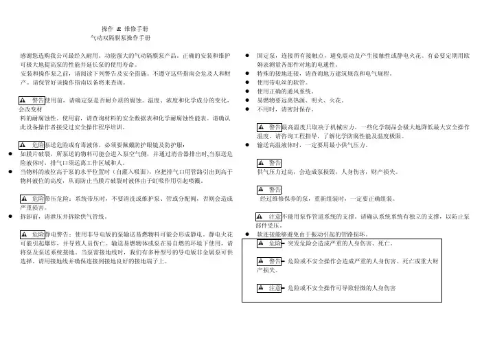
操作 & 维修手册气动双隔膜泵操作手册感谢您选购我公司最经久耐用、功能强大的气动隔膜泵产品。
正确的安装和维护可极大地提高泵的性能并延长泵的使用寿命。
安装和操作泵之前,请阅读下列警告及安全措施。
不遵守这些指南会危及人和财产。
请保管好该操作指南以备将来查询。
警告使用前,请确定泵是否耐介质的腐蚀。
温度、浓度和化学成分的变化,会改变材料的耐腐蚀性。
使用前,请查询材料的安全数据表和化学耐腐蚀性能表。
请确认此设备操作者接受过安全操作程序培训。
危险泵送危险或有毒液体,必须要佩戴防护眼镜及防护服:z如膜片破裂,所泵送的物料可能会进入泵空气侧,并通过消音器排出时,当泵送危险液体时,排气口须远离工作区域和人。
z当物料的液位高于泵的水平位置时(自灌入吸面),应把排气口用管路引出到高于物料液位的高度,从而防止当膜片破裂时液体由于虹吸作用引起喷溅。
危险带压危险:系统带压时,不要清洗或维护泵、管或分配阀,否则会造成严重损害。
z拆卸前,请泄压并拆除供气管线。
危险静电警告:使用非导电版的泵输送易燃物料可能会形成静电。
静电火花可能引起爆炸,并导致人员伤亡。
输送易燃物体或泵在易自燃的环境下使用,请将泵及泵送系统接地。
当泵需接地线时,我们有多种型号的导电版非金属泵可供选择。
请用接地线并确保连接到接地良好的接地端子上。
z固定泵,连接所有接触点,避免震动及产生接触性或静电火花。
有必要定期用欧姆表测量各部件对地的电通性。
z特殊的接地连接,请查询地方建筑规范和电气规程。
z使用带电丝的软管。
z使用正确的通风系统。
z易燃物要远离热源、明火、火花。
z不用时,请密封保存。
警告最高温度只取决于机械应力。
一些化学制品会极大地降低最大安全操作温度。
请咨询工程指导,了解化学防腐性能及温度极限。
z输送高温液体时,一定要用最小供气压力。
警告供气压力过高,会造成泵损毁,人身伤害,财产损失。
警告经过维修保养的泵,重新组装时,一定要正确组装。
注意不能用泵作管道系统的支撑。
BQG-150-0.2(666170-3EB-C)操作手册
BQG-150/0.2(666170-3EB-C)气动隔膜泵操作和维护手册执行标准:JB/T8697-1998Q/IRGT009-2008英格索兰(桂林)工具有限公司广西桂林市朝阳路55号邮编:541004电话:(086)773-5878119传真:(086)773-5876565前言使用本产品的用户,请仔细阅读本说明书,以便正确使用本产品并充分发挥其优良性能。
对未经咨询便对本产品擅自改动的用户,英格索兰公司对造成的伤害不承担任何的责任。
本说明书包含重要的安全信息。
不遵守本手册规程,可能会造成人身伤害或财产损失。
英格索兰公司对造成的伤害不承担任何的责任。
一.操作和安全预防措施阅读、理解并遵照此处信息操作,以免出现伤害或财产损失。
1、气体压力过大。
可能导致人员伤害、泵体损坏或者财产损失。
①进气压力不允许超过泵铭牌所注的最大允许值;②务必确保软管和其他部件能承受泵所产生的液体压力。
检查所有软管的损坏或磨损情况。
确保分配装置干净,工作可靠。
2、静电火花。
可能发生爆炸。
导致严重伤害或死亡。
请将泵和泵送系统接地。
①火花可能点燃易燃材料和蒸汽;②当泵吸、冲洗、再循环或喷射易燃材料时,如油漆、溶剂、腊克漆等,或者在使用位置周围的环境大气可导致自燃时,泵送系统和喷射的物体必须接地。
将分配阀或设备、容器、软管以及将材料抽吸到其中的任何物体接地;③使用泵体上提供的接地端。
使用ARO零件号66885-1接地工具箱或将适当的接地线(最小12线规直径)连接到良好的接地点;④确保泵体、连接头和所有接触点的安全,以避免振动和接触或产生静电火花;⑤咨询当地建筑条例和电工规程中的特殊接地要求;⑥接地后,定期检验接地电路的连续性。
用欧姆计进行测试,确保每个部件(如软管、泵、夹头、容器等)到接地端的连续性。
欧姆计应当显示0.1欧姆或者更小的数值;⑦将出口软管、分配阀门或设备浸入所分配的材料中,避免所泵送的材料自由流动;⑧使用插有电线的软管;⑨使用正确的通风设备;⑩使易燃物品远离热源、明火和火花;⑪当不使用时,请关闭容器。
ChemSafe 307气动隔膜泵3A3549F说明书
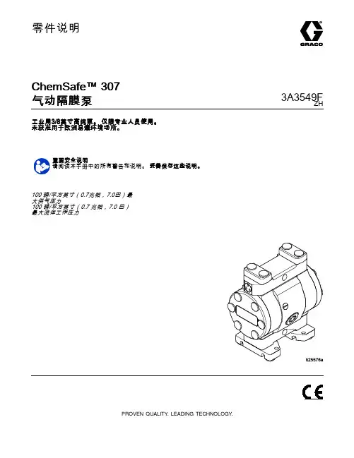
零件说明ChemSafe™307气动隔膜泵3A3549F ZH 工业用3/8英寸高纯泵。
仅限专业人员使用。
未获准用于欧洲易爆环境场所。
重要安全说明请阅读本手册中的所有警告和说明。
妥善保存这些说明。
100磅/平方英寸(0.7兆帕,7.0巴)最大供气压力100磅/平方英寸(0.7兆帕,7.0巴)最大流体工作压力PROVEN QUALITY.LEADING TECHNOLOGY.Contents警告 (3)配置编号表格 (6)安装 (8)一般信息 (8)将螺栓旋紧 (8)减少气蚀秘诀 (8)安装泵 (9)系统接地 (10)空气管路 (10)排气通风 (11)流体供应管路 (12)流体出口管路 (12)Operation (13)将螺栓旋紧 (13)首次使用前冲洗泵 (13)起动和调节泵 (13)泄压步骤 (14)关闭泵 (14)维护 (15)维护计划 (15)润滑 (15)拧紧螺纹连接处 (15)冲洗和储存 (15)故障排除 (16)修理 (18)拆卸流体部分 (18)拆卸中心部分 (19)重新装配中心部分 (19)重新安装流体部分 (20)扭矩说明 (22)部件 (24)配件包 (26)尺寸 (27)性能图表 (28)技术数据 (29)23A3549F警告警告以下为针对本设备的设置、使用、接地、维护及修理的警告。
惊叹号标志表示一般性警告,而各种危险标志则表示与特定操作过程有关的危险。
当本手册正文中或警告标记上出现这些符号时,请回头查阅这些警告。
若产品特定的危险标志和警告未出现在本节内,则可能出现在本手册的其他章节。
3A3549F3警告43A3549F警告3A3549F5配置编号表格配置编号表格检查铭牌(ID),查看泵的配置编号。
使用下表定义泵组件。
示例配置编号307PT-P01APT3PTPTPOPT307PT P01A PT3PT PT PO PT泵型号中心部分和空气阀流体盖和歧管阀座阀球隔膜歧管和阀座密封垫泵中心部分和空气阀材料流体盖和歧管307PT3/8英寸PTFE P01A带常温常压空气入口的聚丙烯中心PT3PTFE,常温常压307UH3/8英寸UHMWPE P03A带bspt空气入口的聚丙烯中心PT4PTFE,bsptUH3UHMWPE,常温常压UH4UHMWPE,bspt阀座材料阀球材料隔膜材料歧管和阀座密封材料PT PTFE PT PTFE BN丁腈橡胶PT PTFEEP三元乙丙橡胶PO超模压PTFE63A3549F配置编号表格型号型号泵空气与流体连接螺纹流体盖和歧管球与阀座隔膜歧管密封件24X428‡英制锥螺纹24X427‡3/83/8英英寸PTFE 标准管螺纹PTFE24X504英制锥螺纹24X503标准管螺纹二次成型PTFE/EPDM24X536英制锥螺纹24X537标准管螺纹三元乙丙橡胶24X502英制锥螺纹24X5013/8英寸UHMWPE 标准管螺纹UHMWPTFE丁腈橡胶PTFE‡ 符合 FDA3A3549F 7安装安装一般信息所示的典型安装仅用作系统组件的选择和安装指南。
气动隔膜泵BQG-350-2操作手册
B QG QG--35350/0.0/0.0/0.22气动隔膜泵气动隔膜泵操 作 和 维 护 手 册执行标准:JB/T8697-1998Q/IRGT009-2009英格索兰(桂林)工具有限公司 广西桂林市朝阳路55号 邮编:541004电话:(086)773-5878119 传真:(086)773-5876565 前言前言使用本产品的用户使用本产品的用户,,请仔细阅读本说明书请仔细阅读本说明书,,以便正确使用本产品并充分发挥其优良性能良性能。
对未经咨询便对本产品擅自改动的用户对未经咨询便对本产品擅自改动的用户,,英格索兰公司对造成的伤害英格索兰公司对造成的伤害不不承担任何的责任的责任。
本说明书包含重要的安全信息本说明书包含重要的安全信息。
不遵守本手册规程不遵守本手册规程,,可能会造成人身伤害或财产损失可能会造成人身伤害或财产损失。
英格索兰公司对造成的伤英格索兰公司对造成的伤害不承担任何的责任害不承担任何的责任。
一.操作和安全预防措施操作和安全预防措施阅读、理解并遵照此处信息操作,以免出现伤害或财产损失。
1、 气体压力过大。
可能导致人员伤害、泵体损坏或者财产损失。
① 进气压力不允许超过泵铭牌所注的最大允许值;② 务必确保软管和其他部件能承受泵所产生的液体压力。
检查所有软管的损坏或磨损情况。
确保分配装置干净,工作可靠。
2、 静电火花。
可能发生爆炸。
导致严重伤害或死亡。
请将泵和泵送系统接地。
① 火花可能点燃易燃材料和蒸汽;② 当泵吸、冲洗、再循环或喷射易燃材料时,如油漆、溶剂、腊克漆等,或者在使用位置周围的环境大气可导致自燃时,泵送系统和喷射的物体必须接地。
将分配阀或设备、容器、软管以及将材料抽吸到其中的任何物体接地;③ 使用泵体上提供的接地端。
使用ARO 零件号66885-1接地工具箱或将适当的接地线(最小12线规直径)连接到良好的接地点;④ 确保泵体、连接头和所有接触点的安全,以避免振动和接触或产生静电火花; ⑤ 咨询当地建筑条例和电工规程中的特殊接地要求; ⑥ 接地后,定期检验接地电路的连续性。
气动隔膜泵使用说明
气动隔膜泵使用说明气动隔膜泵工作原理:气动隔膜泵是以压缩空气为动力和按照1∶1 比率的设计而进行工作的。
一个隔膜室的内侧将被交替地增压而同时另一个隔膜室被排空。
这会导致通过紧固在隔膜中央(以金属板连接)的普通杆连接的隔膜产生摆动。
(因为一个隔膜在执行排放冲程而另一个则在对应的隔膜室中被拉动并执行吸气冲程)。
空气压力作用于隔膜的整个内表面,同时液体从隔膜的对应侧排出。
隔膜在排放冲程期间以平稳的状态工作,同时允许泵以超过200 英尺(61 米)水柱的输送压头进行工作。
为获得最长的隔膜使用期,应使泵尽可能靠近被泵输送的液体。
当正的吸入压头超过10 英尺(3.048 米)的液体高度时,可能需要一个背压式调节装置,以最大限度地提高隔膜的寿命。
对隔膜室的交替式增压和排空通过一个安装在外部的液控4 路阀芯式空气分配阀来实现。
当阀芯移动到阀体的一个端头时,入口压力作用于一个隔膜室,而另一个隔膜室则被排空。
当当阀芯移动到阀体的另一端头时,作用于隔膜室中的压力相反。
空气分配阀的阀芯通过内部的控制阀来移动,该控制阀轮流施压于该空气分配阀的阀芯的一个端头,而排空另一一个端头。
当隔膜板接触到执行器的柱塞时,控制阀会在隔膜冲程的每一端移动。
然后该执行器的柱塞就会将控制阀的阀芯的端头推向启动空气分配阀的位置。
隔膜室与带有为每一个隔膜室配备的进水管和出水管止回阀的歧管相连,保持液体通过泵的单向流动。
气动隔膜泵的安装和启动:尽可能将气动隔膜泵定位于靠近被输送的液体之处。
将吸入管路的长度和接头配件的数量降低到最小。
不要减少吸入管路的直径。
在安装刚性管路时,应在隔膜泵和管路之间安装短的挠性软管段。
挠性软管可以减少输送系统的振动和拉紧。
建议采用增稳装置减少流动中产生的振动。
气源:供气压力不得超过125psi(8.6 巴)。
将泵的空气入口连接到所需的气源中,该气源应有足够的容量和压力,并达到期望的特性。
当进气管为刚性管路时,在泵和管路之间安装一个直径不超过1/2″的短的挠性软管段。
QBY气动隔膜泵使用说明书及选型
上海沈泉泵阀制造有限公司■ 性能简介既能抽送流动的液体,又能输送一些不易流动的介质,具有自吸泵、潜水泵、屏蔽泵、泥浆泵和杂质泵等输送机械的许多优点。
1、不需灌引水,吸程高达7 m ,扬程达7 0 m ,出口压力≥6kgf /c m 2;2、流动宽敞,通过性能好,允许通过最大颗粒直径达1 0 mm 。
抽送泥浆、杂质时,对泵磨损甚微;3、扬程、流量可通过气阀开度实现无级调节(气压调节在1-7 kgf /c m 2之间);4、该泵无旋转部件,没有轴封,隔膜将抽送的介质与泵的运动部件、工件介质完全隔开,所输送的介质不会向外泄漏。
所以抽送有毒、易发挥或腐蚀性介质时,不会造成环境污染和危害人身安全;5、不必用电,在易燃、易爆场所使用安全可靠;6、可以浸没在介质中工作;7、使用方便、工作可靠、开停只需简单地打开和关闭气体阀门,即使由于意外情况而长时间无介质运行或突然停机,泵也不会因此而损坏,一旦超负荷,泵会自地动停机,具有自我保护性能,当负荷恢复正常后,又能自动启动运行;8、结构简单、易损件少,该泵结构简单,安装、维修方便,泵输送的介质不会接触到配气阀,联杆等运动部件,不象其他类型的泵因转子、活塞、齿轮、叶片等部件的磨损而使性能逐步下降;9、可输送较粘的液体(粘度在1万厘泊以下);1 0、本泵无须用油润滑,即使空转,对泵也无任何影响,这是该泵一大特点。
QBY air operated double diaphrafm pumps not only can exhaust the flow liquid,but also can convey some uneasyflowed medium,with the merits of self-pumpinf pump,divinf pump,shield pump,slurry pump and impurity pump etc. 1.It's unnecessary to pour the drawinf water, the suction lift reaches 7 m heifht,the delivery lift reaches 70 mlenfth and the export pressure >6kgf/cm2; 2.Wide flow and flood performance.The diameter allowed to pass the max frain reaches 10mm. The damafe is very less to the pump while exhaustinf the slurry and impurity. 3.The delivery lift and flow can pass the pneumatic valve open to realize the stepless adjustment(the pneumatic pressure adjustment is between 1-7kgf/cm2);4.This pump has no rotary parts and no bearinf seals.The diaphrafm will completely separate the exhausted medium and pump runninfl parts,workin~ medium.The conveyed medium can't be leaked outside.Thus it will not cause the environmental pollution and human body safety danferous while exhaustinf the toxin and flammable or corrosive medium.5.No electricity. It's safe and reliable while usinf in the flammable and explore places.6.It can be soaked in medium.7.It's convenient to use and reliable to work.Only open or close the gas valve body while starting or stopping.Even if no medium operation or pausing suddenly for long time because of accident matters,the pump will not be damaged caused by this.Once over-loading,the pump will automatically stop and possesses the selfprotectionQBY气动隔膜泵function.When the load recovers normally, it also can start automatically.8.Simple structure and less wearin9 parts.This pump is simple in structure, installation and maintenance.The medium conveyed by thepump will not touch the matched pneumatic valve and coupling lever etc.Not like other kinds pumps,the performance will drop down 9radually because of the damages of rotor,gear and vane etc.9.It can transmit the adhesive liquid(the viscosity is below 10000 centipoise). lO.This pump needn't the oil lubricant.Even if idling, it has any influence to the pump. This is a characteristic of this pump.■ 工作原理在泵的两个对称工作腔中A、B中各装有一块隔膜,由中心联杆将其连结成一体。
WILDEN气动隔膜泵手册
EOME n g i nee r in gO p e r a t i o n&M a i n t e n a n c eOriginal™ Series METAL PumpsP15/PV15S i m p l i f y y o u r p r o c e s sWIL-10110-E-02REPLACES EOM-P15/PV15M 5/05SECTION 1 CAUT I ONS—READ F I RST! . . . . . . . . . . . . . . . . . . . . . . . . . . . . . . . . . . . . . . . . . . . . . . . . . . .1SECTION 2WILDEN PUMP DESIGNATION SYSTEM . . . . . . . . . . . . . . . . . . . . . . . . . . . . . . . . . . . .2 SECTION 3HOW IT WORKS—PUMP & AIR DISTRIBUTION SYSTEM . . . . . . . . . . . . . . . . . .3 SECTION 4 D I MENS I ONAL DRAW I NGS . . . . . . . . . . . . . . . . . . . . . . . . . . . . . . . . . . . . . . . . . . . . . . . . . .4SECTION 5 PERFORMANCEA. P15 Performance CurvesRubber-Fitted . . . . . . . . . . . . . . . . . . . . . . . . . . . . . . . . . . . . . . . . . . . . . . . . . . . . . . . . . . . . . .6TPE-Fitted . . . . . . . . . . . . . . . . . . . . . . . . . . . . . . . . . . . . . . . . . . . . . . . . . . . . . . . . . . . . . . . . .6PTFE-Fitted . . . . . . . . . . . . . . . . . . . . . . . . . . . . . . . . . . . . . . . . . . . . . . . . . . . . . . . . . . . . . . . .7Ultra-Flex™-Fitted . . . . . . . . . . . . . . . . . . . . . . . . . . . . . . . . . . . . . . . . . . . . . . . . . . . . . . . . . .7 PV15 Performance CurvesRubber-Fitted . . . . . . . . . . . . . . . . . . . . . . . . . . . . . . . . . . . . . . . . . . . . . . . . . . . . . . . . . . . . . .8TPE-Fitted . . . . . . . . . . . . . . . . . . . . . . . . . . . . . . . . . . . . . . . . . . . . . . . . . . . . . . . . . . . . . . . . .8PTFE-Fitted . . . . . . . . . . . . . . . . . . . . . . . . . . . . . . . . . . . . . . . . . . . . . . . . . . . . . . . . . . . . . . . .9Ultra-Flex™-Fitted . . . . . . . . . . . . . . . . . . . . . . . . . . . . . . . . . . . . . . . . . . . . . . . . . . . . . . . . . .9B. Suction Lift Curves . . . . . . . . . . . . . . . . . . . . . . . . . . . . . . . . . . . . . . . . . . . . . . . . . . . . . . . . . . .10 SECTION 6SUGGESTED INSTALLATION, OPERATION & TROUBLESHOOTING. . . . . . . .11 SECTION 7ASSEMBLY / DISASSEMBLY . . . . . . . . . . . . . . . . . . . . . . . . . . . . . . . . . . . . . . . . . . . . . . . .14SECTION 8EXPLODED VIEW & PARTS LISTINGP15 MetalRubber/TPE/Ultra-Flex™-Fitted . . . . . . . . . . . . . . . . . . . . . . . . . . . . . . . . . . . . . . . . . . . . .22PTFE-Fitted . . . . . . . . . . . . . . . . . . . . . . . . . . . . . . . . . . . . . . . . . . . . . . . . . . . . . . . . . . . . . . .24 PV15 MetalRubber/TPE/Ultra-Flex™-Fitted . . . . . . . . . . . . . . . . . . . . . . . . . . . . . . . . . . . . . . . . . . . . .26PTFE-Fitted . . . . . . . . . . . . . . . . . . . . . . . . . . . . . . . . . . . . . . . . . . . . . . . . . . . . . . . . . . . . . . .28SECTION 9 ELASTOMER OPT I ONS . . . . . . . . . . . . . . . . . . . . . . . . . . . . . . . . . . . . . . . . . . . . . . . . . . . . . .30CAUTION: Do not apply compressed air to theexhaust port — pump will not function.CAUTION: Do not over-lubricate air supply —excess lubrication will reduce pump performance.Pump is pre-lubed.TEMPERATURE LIMITS:Neoprene –17.7°C to 93.3°C 0°F to 200°FBuna-N –12.2°C to 82.2°C 10°F to 180°FEPDM –51.1°C to 137.8°C –60°F to 280°FViton®–40°C to 176.7°C –40°F to 350°FSanifl ex™ –28.9°C to 104.4°C –20°F to 220°FPolytetrafl uoroethylene (PTFE)4.4°C to 104.4°C 40°F to 220°FPolyurethane –12.2°C to 65.6°C 10°F to 150°FTetra-Flex™ PTFE w/Neoprene Backed4.4°C to 107.2°C 40°F to 225°FTetra-Flex™PTFE w/Nordel® Backed-10°C to 137°C 14°F to 280°F NOTE: Not all materials are available for allmodels. Refer to Section 2 for material optionsfor your pump.CAUTION: When choosing pump materials, besure to check the temperature limits for all wettedcomponents. E xample: Viton® has a maximumlimit of 176.7°C (350°F) but polypropylene has amaximum limit of only 79°C (175°F).CAUTION: Maximum temperature limits arebased upon mechanical stress only. Certainchemicals will signifi cantly reduce maximumsafe operating temperatures. Consult ChemicalResistance Guide (E4) for chemical compatibilityand temperature limits.WARNING:Prevention of static sparking — Ifstatic sparking occurs, fire or explosion couldresult. Pump, valves, and containers must begrounded to a proper grounding point whenhandling fl ammable fluids and whenever discharge of static electricity is a hazard.CAUTION: Do not exceed 8.6 bar (125 psig) airsupply pressure.CAUTION: The process fl uid and cleaning fl uidsmust be chemically compatible with all wettedpump components. Consult Chemical ResistanceGuide (E4).CAUTION: Do not exceed 82°C (180°F) air inlet temperature for Pro-Flo V™ models.CAUTION: Pumps should be thoroughly fl ushed before installing into process lines. FDA and USDA approved pumps should be cleaned and/ or sanitized before being used.CAUTION: Always wear safety glasses when operating pump. If diaphragm rupture occurs, material being pumped may be forced out air exhaust.CAUTION: Before any maintenance or repair is attempted, the compressed air line to the pump should be disconnected and all air pressure allowed to bleed from pump. Disconnect all intake, discharge and air lines. Drain the pump by turning it upside down and allowing any fl uid to fl ow into a suitable container.CAUTION: Blow out air line for 10 to 20 seconds before attaching to pump to make sure all pipeline debris is clear. Use an in-line air filter. A 5μ (micron) air fi lter is recommended.NOTE:When installing PTFE diaphragms, it is important to tighten outer pistons simultaneously (turning in opposite directions) to ensure tight fi t. (See torque specifi cations in Section 7.)NOTE: Cast Iron PTF E-fitted pumps come standard from the factory with expanded PTFE gaskets installed in the diaphragm bead of the liquid chamber. PTFE gaskets cannot be re-used. Consult PS-TG for installation instructions during reassembly.NOTE: Before starting disassembly, mark a line from each liquid chamber to its corresponding air chamber. This line will assist in proper alignment during reassembly.CAUTION: Pro-Flo® pumps cannot be used in submersible applications. Pro-Flo V™ is available in both submersible and non-submersible options. Do not use non-submersible Pro-Flo V™ models in submersible applications. Turbo-Flo™ pumps can also be used in submersible applications. CAUTION: Tighten all hardware prior to installation.WIL-10110-E-02 8/06 1 WILDEN PUMP & ENGINEERING, LLC0003 Spark free0010 SS outer piston, spark free0014 BSPT0015 Spark free, BSPT0023 Wing nuts0030 Screen based0033 Screen based, spark free0036 Screen based, BSPT0037 Screen based, spark free, BSPT 0039 Screen based, polyurethane screen 0044 Stallion balls and seats ONLY0047 Stallion externals, balls and seats0068 Saniflo™ FDA, vertical flange0070 Saniflo™ FDA0075 Saniflo FDA, Stallion balls and seats ONLY0079 Tri-clamp fittings, wing nuts0080 Tri-clamp fittings ONLY0100 Wil-Gard I I™ 110V0102 Wil-Gard II™, sensor wires ONLY0103 Wil-Gard I I™ 220V0104 Wil-Gard II™ 110V, spark free0105 Wil-Gard II™ 220V, spark free0108 Wil-Gard II™ 220V, BSPT0109 Wil-Gard II™ 220V, spark free, BSPT0118 Stallion balls and seats ONLY, BSP0120 Saniflo™ FDA, Wil-Gard II™ 110V0330 Wing nuts, BSPT0513 SS outer pistonsNOTE: MOST ELASTOMERIC MATERIALS USE COLORED DOTS FOR IDENTIFICATION.NOTE: Not all models are available with all materials options.Viton® is a registered trademark of DuPont Dow Elastomers.WILDEN PUMP & ENGINEERING, LLC 2 WIL-10110-E-02 8/06WIL-10110-E-02 8/06 3 WILDEN PUMP & ENGINEERING, LLCThe Wilden diaphragm pu mp is an air-operated, positive displacement, self-priming pu mp. These drawings show fl ow pattern through the pump upon its initial stroke. It is assumed the pump has no fl uid in it prior to its initial stroke.FIGURE 1 The air valve directs pressurized air to the back side of diaphragm A. The compressed air is applied directly to the liquid column separated by elastomeric diaphragms. The diaphragm acts as a separation membrane between the compressed air and liquid, balancing the load and removing mechanical stress from the diaphragm. The compressed air moves the diaphragm away from the center of the pump. The opposite diaphragm is pulled in by the shaft connected to the pressurized diaphragm. Diaphragm B is on its suction stroke; air behind the diaphragm has been forced out to atmosphere through the exhaust port of the pump. The movement of diaphragm B toward the center of the pump creates a vacuum within chamber B. Atmospheric pressure forces fl uid into the inlet manifold forcing the inlet valve ball off its seat. Liquid is free to move past the inlet valve ball and fi ll the liquid chamber (see shaded area).FIGURE 2 When the pressurized diaphragm, diaphragm A , r eaches t he l imit o f i ts d ischarge stroke, the air valve redirects pressurized air to the back side of diaphragm B. The pressurized air forces diaphragm B away from the center while pulling diaphragm A to the center. Diaphragm B is now on its discharge stroke. Diaphragm B forces the inlet valve ball onto its seat due to the hydraulic forces developed in the liquid chamber and manifold of the pump. These same hydraulic forces lift the discharge valve ball off its seat, while the opposite discharge valve ball is forced onto its seat, forcing fl uid to fl ow through the pump discharge. The movement of diaphragm A toward the center of the pump creates a vacuum within liquid chamber A. Atmos-pheric pressure forces fl uid into the inlet manifold of the pump. The inlet valve ball is forced off its seat allowing the fl uid being pumped to fi ll the liquid chamber.FIGURE 3 At completion of the stroke,the air valve again redirects air to the back side of diaphragm A, which starts diaphragm B on its exhaust stroke. As the pump reaches its original starting point, each diaphragm has gone through one exhaust and one discharge stroke. This constitutes one complete pumping cycle. The pump may take several cycles to completely prime depending on the conditions of the application.The Pro-Flo ® patented air distribution system incorporates two moving parts: the air valve spool and the pilot spool. The heart of the system is the air valve spool and air valve. This valve design incorporates an unbalanced spool. The smaller end of the spool is pressurized continuously, while the large end is alternately pressurized then exhausted to move the spool. The spool directs pressurized air to one air chamber while exhausting the other. The air causes the main shaft/diaphragm assembly to shift to one side — discharging liquid on that side and pulling liquid in on the other side. When the shaft reaches the end of its stroke, the inner piston actuates the pilot spool, which pressurizes and exhausts the large end of the air valve spool. The repositioningof the air valve spool routes the air to the other air chamber.WILDEN PUMP & ENGINEERING, LLC 4 WIL-10110-E-02 8/06WIL-10110-E-02 8/06 5WILDEN PUMP & ENGINEERING, LLCDIMENSIONSITEM METRIC (mm)STANDARD (inch)A 50519.9B 58 2.3C 38615.2D 76230.0E 82332.4F 71 2.8G 84 3.3H 38915.3J 2168.5K 40616.0L 36314.3M 30712.1N 25710.1P 28211.1R 150.6S 71 2.8T 66 2.6U 30512.0V 43 1.7W 30512.0X 47818.8Y15 DIA..6 DIA.DIMENSIONSITEM METRIC (mm)STANDARD (inch)A 52120.5B 71 2.8C 39615.6D 76730.2E 81031.9F 89 3.5G 2168.5H 40616.0J 42416.7K 35614.0L 30512.0M 25710.1N 27911.0P150.6PV15 Metal Saniflo FDAPV15 Metal76 mm (3")WILDEN PUMP & ENGINEERING, LLC 6WIL-10110-E-02 8/06Flow rates indicated on chart were determined by pumping water.For optimum life and performance, pumps should be specified so that daily operation parameters will fall in the center of the pump performance curve.Example: To pump 227 lpm (60 gpm)against a discharge head of 3.7 bar (54 psig) requires 4.1 bar (60 psig) and 61 Nm 3/h (36 scfm) air consumption.Caution: Do not exceed 8.6 bar (125 psig) air supply pressure.Flow rates indicated on chart were determined by pumping water.For optimum life and performance, pumps should be specified so that daily operation parameters will fall in the center of the pump performance curve.Example: To pump 227 lpm (60 gpm)against a discharge pressure head of 3.4 bar (50 psig) requires 4.1 bar (60 psig) and 58 Nm 3/h (34 scfm) air consumption. Caution: Do not exceed 8.6 bar (125 psig) air supply pressure.WIL-10110-E-02 8/06 7WILDEN PUMP & ENGINEERING, LLCFlow rates indicated on chart were determined by pumping water.For optimum life and performance, pumps should be specified so that daily operation parameters will fall in the center of the pump performance curve.Example: To pump 227 lpm (60 gpm)against a discharge pressure head of 3.3 bar (48 psig) requires 4.1 bar (60 psig) and68 Nm 3/h (40 scfm) air consumption. Caution: Do not exceed 8.6 bar (125 psig)air supply pressure.Flow rates indicated on chart were determined by pumping water.For optimum life and performance, pumps should be specified so that daily operation parameters will fall in the center of the pump performance curve.Example: To pump 227 lpm (60 gpm)against a discharge pressure head of 2.9 bar (42 psig) requires 4.1 bar (60 psig) and 80 Nm 3/h (47 scfm) air consumption. Caution: Do not exceed 8.6 bar (125 psig) air supply pressure.WILDEN PUMP & ENGINEERING, LLC 8WIL-10110-E-028/06Flow rates indicated on chart were determined by pumping water.For optimum life and performance, pumps should be specifi ed so that daily operation parameters will fall in the center of the pump performance curve.against a discharge head of 3.6 bar (52 psig) requires 5.5 bar (80 psig) and 170 Nm 3/h (100 scfm) air consumption. Caution: Do not exceed 8.6 bar (125 psig) air supply pressure.Flow rates indicated on chart were determined by pumping water.For optimum life and performance, pumps should be specifi ed so that daily operation parameters will fall in the center of the pump performance curve.against a discharge pressure head of 2.6 bar (38 psig) requires 4.1 bar (60 psig) and 136 Nm 3/h (80 scfm) air consumption.Caution: Do not exceed 8.6 bar (125 psig) air supply pressure.Flow rates indicated on chart were determined by pumping water.For optimum life and performance, pumps should be specifi ed so that daily operation parameters will fall in the center of the pump performance curve.against a discharge pressure head of 4.3 bar (62 psig) requires 5.5 bar (80 psig) and 136 Nm 3/h (80 scfm) air consumption.Caution: Do not exceed 8.6 bar (125 psig) air supply pressure.Flow rates indicated on chart were determined by pumping water.For optimum life and performance, pumps should be specifi ed so that daily operation parameters will fall in the center of the pump performance curve.against a discharge pressure head of 3.5 bar (51 psig) requires 4.1 bar (60 psig) and 68 Nm 3/h (40 scfm) air consumption. Caution: Do not exceed 8.6 bar (125 psig) air supply pressure.Suction lift curves are calibrated for pumps operating at 305 m (1,000') above sea level. This chart is meant to be a guide only. There are many variables which can affect your pump’s operating characteristics. The number of intake and discharge elbows, viscosity of pumping fl uid, elevation (atmospheric pressure) and pipe friction loss all affect the amount of suction lift your pump will attain.Wilden pumps are designed to meet the performance requirements of even the most demanding pumping applications. They have been designed and manufactured to the highest standards and are available in a variety of liquid path materials to meet your chemical resistance needs. Refer to the performance section of this manual for an in-depth analysis of the performance characteristics of your pump. Wilden offers the widest variety of elastomer options in the industry to satisfy temperature, chemical compatibility, abrasion resistance and fl ex concerns.The suction pipe size should be at least the equivalent or larger than the diameter size of the suction inlet on your Wilden pump. The suction hose must be non-collapsible, reinforced type as these pumps are capable of pulling a high vacuum. Discharge piping should also be the equivalent or larger than the diameter of the pump discharge which will help reduce friction losses. It is critical that all fi ttings and connections are airtight or a reduction or loss of pump suction capability will result.INSTALLATION: Months of careful planning, study, and selection efforts can result in unsatisfactory pump performance if installation details are left to chance.Premature failure and long term dissatisfaction can be avoided if reasonable care is exercised throughout the installation process.LOCATION: Noise, safety, and other logistical factors usually dictate where equipment will be situated on the production floor. Multiple installations with confl icting requirements can result in congestion of utility areas, leaving few choices for additional pumps.Within the framework of these and other existing conditions, every pump should be located in such a way that six key factors are balanced against each other to maximum advantage.ACCE SS: First of all, the location should be accessible. If it’s easy to reach the pump, maintenance personnel will have an easier time carrying out routine inspections and adjustments. Should major repairs become necessary, ease of access can play a key role in speeding the repair process and reducing total downtime.AIR SUPPL Y: E very pump location should have an air line large enough to supply the volume of air necessary to achieve the desired pumping rate. Use air pressure up to a maximum of 8.6 bar (125 psig) depending on pumping requirements.For best results, the pumps should use a 5μ (micron) air filter, needle valve and regulator. The use of an air fi lter before the pump will ensure that the majority of any pipeline contaminants will be eliminated.SOLENOID OPERATION: When operation is controlled by a solenoid valve in the air line, three-way valves should be used. This valve allows trapped air between the valve and the pump to bleed off which improves pump performance. Pumping volume can be estimated by counting the number of strokes per minute and then multiplying the fi gure by the displacement per stroke.MUFFL E R: Sound levels are reduced below OSHA specifications using the standard Wilden muffl er. Other mufflers can be used to further reduce sound levels, but they usually reduce pump performance.E LE VATION: Selecting a site that is well within the pump’s dynamic lift capability will assure that loss-of-prime issues will be eliminated. In addition, pump effi ciency can be adversely affected if proper attention is not given to site location.PIPING: Final determination of the pump site should not be made until the piping challenges of each possible location have been evaluated. The impact of current and future installations should be considered ahead of time to make sure that inadvertent restrictions are not created for any remaining sites.The best choice possible will be a site involving the shortest and straightest hook-up of suction and discharge piping. Unnecessary elbows, bends, and fi ttings should be avoided. Pipe sizes should be selected to keep friction losses within practical limits. A ll piping should be supported independently of the pump. In addition, the piping should be aligned to avoid placing stress on the pump fi ttings.Flexible hose can be installed to aid in absorbing the forces created by the natural reciprocating action of the pump. If the pump is to be bolted down to a solid location, a mounting pad placed between the pump and the foundation will assist in minimizing pump vibration. Flexible connections between the pump and rigid piping will also assist in minimizing pump vibration. If quick-closing valves are installed at any point in the discharge system, or if pulsation within a system becomes a problem, a surge suppressor (SD E qualizer®) should be installed to protect the pump, piping and gauges from surges and water hammer.If the pump is to be used in a self-priming application, make sure that all connections are airtight and that the suction lift is within the model’s ability. Note: Materials of construction and elastomer material have an effect on suction lift parameters. Please refer to the performance section for specifi cs.When pumps are installed in applications involving fl ooded suction or suction head pressures, a gate valve should be installed in the suction line to permit closing of the line for pump service.Pumps in service with a positive suction head are most effi cient when inlet pressure is limited to 0.5–0.7 bar (7–10 psig). Premature diaphragm failure may occur if positive suction is 0.7 bar (10 psig) and higher.SUBME RSIBLE APPLICATIONS: Pro-Flo V™ pumps can be used for submersible applications, when using the Pro-Flo V™ submersible option. Turbo-Flo™ pumps can also be used for submersible applications.NOTE: Pro-Flo® and Accu-Flo™ pumps are not submersible.ALL WILDEN PUMPS ARE CAPABLE OF PASSING SOLIDS.A STRAINER SHOULD BE USED ON THE PUMP INTAKE TO E NSURE THAT THE PUMP'S RATE D SOLIDS CAPACITY IS NOT EXCEEDED.CAUTION: DO NOT E XCE E D 8.6 BAR (125 PSIG) AIR SUPPLY PRESSURE.NOTE: In the event of a power failure, the shut off valve should be closed, if the restarting of the pump is not desirable once power is regained.AIR OPERATED PUMPS:To stop the pump from operating in an emergency situation, simply close the shut off valve (user supplied) installed in the air supply line. A properly functioning valve will stop the air supply to the pump, therefore stopping output. This shut off valve should be located far enough away from the pumping equipment such that it can be reached safelyin an emergency situation.OPERATION: The P15 and PV15 are pre-lubricated, and do not require in-line lubrication. Additional lubrication will not damage the pump, however if the pump is heavily lubricated by an external source, the pump’s internal lubrication may be washed away. If the pump is then moved to a non-lubricated location, it may need to be disassembled and re-lubricated as described in the ASSEMBLY/DISASSEMBLY INSTRUCTIONS.Pump discharge rate can be controlled by limiting the volume and/or pressure of the air supply to the pump. An air regulator is used to regulate air pressure.A needle valve is used to regulate volume. Pump discharge rate can also be controlled by throttling the pump discharge by partially closing a valve in the discharge line of the pump. This action increases friction loss which reduces fl ow rate. (See Section 5.) This is useful when the need exists to control the pump from a remote location. When the pump discharge pressure equals or exceeds the air supply pressure, the pump will stop; no bypass or pressure relief valve is needed, and pump damage will not occur. The pump has reached a “deadhead” situation and can be restarted by reducing the fl uid discharge pressure or increasing the air inlet pressure. The Wilden P15 and PV15 pumps run solely on compressed air and does not generate heat, therefore your process fl uid temperature will not be affected.MAINT E NANC E AND INSP E CTIONS: Since each application is unique, maintenance schedules may be different for every pump. Frequency of use, line pressure, viscosity and abrasiveness of process fl uid all affect the parts life of a Wilden pump. Periodic inspections have been found to offer the best means for preventing unscheduled pump downtime. Personnel familiar with the pump’s construction and service should be informed of any abnormalities that are detected during operation.RECORDS: When service is required, a record should be made of all necessary repairs and replacements. Over a period of time, such records can become a valuable tool for predicting and preventing future maintenance problems and unscheduled downtime. In addition, accurate records make it possible to identify pumps that are poorly suited to their applications.T R O U B L E S H O O T I N GPump will not run or runs slowly.1. E nsure that the air inlet pressure is at least 0.4 bar(5 psig) above startup pressure and that the differentialpressure (the difference between air inlet and liquid discharge pressures) is not less than 0.7 bar (10 psig). 2. C heck air inlet fi lter for debris (see recommendedinstallation).3. C heck for extreme air leakage (blow by) whichwould indicate worn seals/bores in the air valve, pilot spool, main shaft.4. D isassemble pump and check for obstructionsin the air passageways or objects which would obstruct the movement of internal parts.5. C heck for sticking ball check valves. If materialbeing pumped is not compatible with pump elastomers, swelling may occur. Replace ball check valves and seals with proper elastomers.Also, as the check valve balls wear out, they become smaller and can become stuck in the seats. In this case, replace balls and seats.6. C heck for broken inner piston which will cause theair valve spool to be unable to shift.7. Remove plug from pilot spool exhaust.Pump runs but little or no product fl ows.1. C heck for pump cavitation; slow pump speeddown to allow thick material to flow into liquid chambers.2. V erify that vacuum required to lift liquid is notgreater than the vapor pressure of the material being pumped (cavitation).3. C heck for sticking ball check valves. If material beingpumped is not compatible with pump elastomers, swelling may occur. Replace ball check valves and seats with proper elastomers. Also, as the check valve balls wear out, they become smaller and can become stuck in the seats. In this case, replace balls and seats.Pump air valve freezes.1. C heck for excessive moisture in compressedair. E ither install a dryer or hot air generator for compressed air. Alternatively, a coalescing fi lter may be used to remove the water from the compressed air in some applications.Air bubbles in pump discharge.1. Check for ruptured diaphragm.2. C heck tightness of outer pistons (refer to Section 7).3. C heck tightness of fasteners and integrity ofo-rings and seals, especially at intake manifold.4. Ensure pipe connections are airtight.Product comes out air exhaust.1. Check for diaphragm rupture.2. Check tightness of outer pistons to shaft.Step 1.Before starting disassembly, mark a line from each liquid chamber to its corresponding air chamber. This line will assist in proper alignment during reassembly. Step 2Utilizing a 11/16" wrench, removethe two small clamp bands thatfasten the discharge manifold tothe liquid chambers.Step 3Remove the discharge manifold toexpose the valve balls and seats.Inspect ball cage area of manifoldfor excessive wear or damage.Step 4Remove the discharge valve balls and seats from the liquid chambers and inspect for nicks, chemical attack or abrasive wear. Replace worn parts with genuine Wilden parts for reliable performance.Step 5Turn pump upside down andremove the two small clamp bandswhich fasten the intake manifold tothe liquid chambers.Step 6Lift intake manifold to expose intakevalve balls and seats. Inspect ballcage area of liquid chamber forexcessive wear or damage.Step 7Remove one set of large clamp bands which secure one liquid chamber to the center section using two 3/4" wrenches. Step 8Lift liquid chamber away fromcenter section to expose diaphragmand outer piston.Step 9Using an adjustable wrench, or byrotating the diaphragm by hand,remove the diaphragm assembly.。
气动隔膜泵操作分享
气动隔膜泵操作分享
一、启动前检查
1、启动隔膜泵之前,要检查泵螺丝及接头不能松动,确认压缩空气阀门处于关闭状态,液体出入口均处于全开状态。
二、泵的启动
1、缓慢开启隔膜泵压缩空气阀门至1/2位置,启动隔膜泵,待隔膜泵启动后逐渐开大隔膜泵气阀,直到全开;
2、如隔膜泵往复速度太快,液体流量大,应将气阀关小,以达最佳的输出效果。
三、泵的停机
1、可先关闭泵的进料阀,让泵运行3到4个往复,将料液排出再关闭气阀;
2、气阀关闭后,液体的出口阀门也应一并关闭;
3、如遇紧急情况需停泵,只需关闭隔膜泵气阀即可,但随后要将泵内的料液排出。
四、隔膜泵使用安全注意事项
1、隔膜泵压缩空气压力不应超过0.7Mpa;
2、流体中最大颗粒不超过10mm;
3、要周期性地检查泵壳接地系统,要求接地电阻小于100欧姆;
4、不允许长时间空运转;
5、当隔膜失效时,输送的物料会从排气消音器中喷出,隔膜泵膜片破裂时,要及时拆开清洗并更换膜片;
6、隔膜泵启动时应缓慢开启气阀,防止因突然开气阀引起隔膜泵剧烈震动而损坏设备;
7、流体的高压可能会导致严重的人身伤亡和财产损失,不要在泵加压时,对泵及物料管系统进行任何的维修工作,如要作维修时,先切断泵的进气,打开旁通的卸压机构使管路系统卸压,慢慢松开连接的各管路接头。
气动隔膜泵操作规程范本(2篇)
气动隔膜泵操作规程范本一、安全操作规程1. 在操作气动隔膜泵之前,必须穿戴好安全防护装备,包括防护眼镜、防护手套和防护鞋。
2. 在操作过程中,禁止穿戴有松散衣物和长发,以及佩戴珠宝等物品。
3. 确保工作区域的干净整洁,并清除任何可能造成绊倒或滑倒的障碍物。
4. 在操作气动隔膜泵之前,必须检查泵体、管道和连接件是否存在泄漏或损坏,如有问题需立即修复。
5. 在操作气动隔膜泵之前,必须确保气源(压缩空气)的压力稳定,并且按照规定的压力范围进行调整。
6. 停止使用气动隔膜泵时,必须切断气源,并将泵内残余气体放空。
二、操作步骤规程1. 打开气源供应,调节气源压力至指定范围。
2. 检查气动隔膜泵的各部分连接是否牢固,如有松动或异常情况,应停止使用并及时处理。
3. 将输入介质管道连接到泵的入口,输出介质管道连接到泵的出口,并确保连接件处于紧固状态。
4. 打开进气阀,使气动隔膜泵吸入介质。
5. 等待一段时间,确保气动隔膜泵内部充满介质。
6. 打开出口阀,泵开始工作,输出介质顺利流出。
7. 在使用气动隔膜泵期间,定期检查泵体、管道和连接件是否存在泄漏或损坏,如有问题及时处理。
8. 在操作过程中,如果发现气动隔膜泵出现异常情况,如异常噪音或振动,应立即停止使用,并排除故障后方可继续使用。
三、维护保养规程1. 每次使用气动隔膜泵后,应将其清洗干净,并存放在干燥通风的地方。
2. 定期检查气动隔膜泵的各部分是否存在磨损或老化现象,如有问题应及时更换。
3. 定期检查气动隔膜泵的密封性能,如发现密封件松动或磨损,应及时更换。
4. 定期清洗气动隔膜泵的各个部分,包括泵体、阀门和连接件等,确保其正常运行。
5. 对于长时间不使用的气动隔膜泵,应将其存放在干燥通风的地方,并进行适当的防锈处理。
6. 定期对气动隔膜泵进行维护保养,包括清洗、润滑和调整等,确保其性能稳定。
总结:以上是气动隔膜泵操作规程的简单范本,希望能对用户使用气动隔膜泵时有所帮助。
气动式隔膜泵使用说明书
原因
吸入管或填料处进气 转向不对 泵距离吸入液面过高 吸入管堵塞 泵内产生磨擦 轴承损坏 流量偏大 比重超过正常情况 电机轴与泵轴不对中 电机轴与泵轴不对中 轴弯曲 泵内有磨擦 轴承内下入异物 轴承装配不合理 轴承损坏 流量不均匀或有抽空现象 吸入管进气或有抽空现象 基础固定不良 管路布置不合理 产生汽蚀 渣浆沉淀将 水结冰卡死叶轮
即使空转也无任何影响。可保障日复一日的的运行。
d) 具有自我保护性能,一旦超负荷工作会自动停机,一旦负荷恢复正常又自动启动运行。
轴封有两种形式:
3. 安 装
3.1 隔膜泵安装
见下图尺寸 A、B 为泵体安装尺寸。
3.1 系统安装
按
启动前按下列步骤检查整个机组:
QBK 系列 煤矿用气动式隔膜泵
使 用 说 明 书
(执行标准:XXXXXXXXXX) XXXXXXXXX 有限公司
目
录
1. 概述…………………………………………1 2. 结构说明……………………………………3 3. 安装…………………………………………5 4. 运转…………………………………………6 5. 维护保养……………………………………8 6. 可能发生的故障及解决的办法……………9
型号意义:
例如:
QBK 50 - □
泵体材料 口径 气动隔膜
型号 QBK-50
表 1: QBK 系列气动式隔膜泵基本参数
最大流量 出口压力
吸程 最大允许颗粒直径 最大空气消耗量
(L/Min)
(Bar)
(m)
(mm)
(L/min)
568
8.4
6
6.3
4900
2、 结构说明