EC7520有源光电隔离型接口转换器说明书
艾顿 bypass 隔离自动转换交换器说明书

Unmatched performance and reliabilityBypass isolation ATS Eaton’s bypass isolation automatic transfer switch (ATS) is designed to provide unmatched performance, reliability and versatility for critical standby power applications. Supervisory intelligence is provided by an ATC-900 or ATC-300+ controller, delivering operational simplicity and field adaptability coupled with diagnostic and troubleshooting capabilities. The bypass isolation ATS design is ideal for those applications where the ability to perform maintenance is required without interrupting power to life safety and other critical loads.Product configuration• Automatic operation—ATS and bypass switch• Open and closed transition• 100–1200 A rating• Two-, three- or four-pole• NEMA T 1, 3R• Up to 600 Vac, three- orfour-wire, 60 Hz or 50/60 Hz• Drawout ATS and fixedbypass switch, facilitatingconcurrent maintenance• Service entranceFeatures and benefitsProven performanceand reliability• Automatic and non-automaticoperation modes are availableto provide multiple methods oftransferring the load betweenpower sources• Manual operation allowsunloaded transfer betweenpower sources for allproduct configurations• UL T 1008 Listed short-circuitand short-time (select catalognumbers only) withstandclosing current ratingsmaximize system reliabilitySimplified installationand integration• Factory-configured powersource and load terminalsfor top/bottom cable ingress• Removable enclosure panelsprovide front and rear accessto cable terminal connections• Seismic certified to OSHPD,CBC, IBC and UBCEnhanced safety• Two-door, compartmentalizedconstruction provides steelbarriers, protecting workers• Integral safety interlocksautomatically open the maincontacts prior to the ATSbeing isolated for test orremoved for serviceImproved serviceability• Two-door design eliminatesthe need to scheduleshutdowns for routine test,inspection or maintenanceof the ATS• Drawout design allows theATS to be disconnectedfrom the electrical bus andisolated in cell for regulartesting as prescribed bycode (NFPA T 70, 99, 110)• Testing of the isolated ATScan be performed whilethe bypass switch is in theautomatic or non-automaticmode of operationDesign featuresDual automatic technology Eaton’s bypass isolationtransfer switch design includes an automatic bypass switch and an ATS housed within a single assembly.Regardless of which power switch is actively distributing power, redundant automatic operation provides for a rapid load transfer and restoration of power to life safety and critical loads, eliminating the need for active supervision by qualified personnel.Segmented construction The ATS and automatic bypass switch are housed in separate compartments, with robust steel walls, that isolate the power switches from each other to facilitate ease of maintenance and worker safety. Eachcompartment includes a door with padlockable handle. This design prevents the possibility of inadvertent contact andunnecessary exposure to power cable terminations and energized electrical control components.Drawout ATS and fixed-mounted bypassService personnel can rack-out and isolate the ATS (with compartment door closed) from the electrical bus for routine test or exercise. A Kirk T -key interlock prevents access to the racking mechanism until the load connection has been transitioned to the automatic bypass switch.Opening the compartment door allows the ATS to be completely drawn out of the cell for inspection or maintenance.Safety interlocks prevent rack-out or rack-in of the ATS from the electrical bus with the main contacts closed. The automatic bypass switch is fixed mounted to the electrical bus and stands ready to initiate an automatic load transfer when the ATS is undergoing maintenance.Multi-tap control power transformerSystem voltage can be fieldconfigured via a multi-tap control power transformer (CPT) with quick-disconnect plugs.T ransition to bypass mode When maintenance or testing of the ATS needs to be performed, qualified personnel can easily and quickly transition the load connection between the ATS and automatic bypass switch using door-mounted operator controls fitted with indication lights. The transition occurs in a make-before-break fashion, ensuring continuous power flow to loads.Multiple operation modes Operation is possible in the following modes:• Automatic • Non-automatic •Manual AIn automatic mode, the transfer switch is self-acting, and atransfer is automatically initiated by the intelligent logic controller.In non-automatic mode(optional), a transfer is initiated by the operator using a door-mounted selector switch.In manual mode, a transfer is initiated by the operator using controls mounted directly on the automatic bypass switch or ATS.Alternatively, a transfer can be initiated remotely via an HMi remote annunciator controller.A Manual operation (unloaded) is provided forall product configurations.for top and bottom cable terminationFixed-mounted automatic Drawout ATS can be isolated for test within compartment orand automatic bypassswitch compartments600–1200 A rating (480 V), NEMA 1 enclosure100–400 A rating (480 V), NEMA 1 enclosureFixed-mounted automatic Drawout ATS can within compartmentor completely removedRemoveable optionpanels allow front access for top and bottom cableterminationDrawout ATS removed for bench level inspection/Automatic bypass switch stands ready to transfer load2EATON Bypass isolation automatic transfer switchesStandard enclosure dimensions and weightsDimensions and weights shown are approximate and subject to change. Reference product outline drawings for the latest information.NEMA 1 enclosure NEMA 3R enclosureNEMA 12/4X enclosureTransferswitch rating Device Dimensions in inches (mm)Normal,emergency, loadNeutral A Weight ABCA Neutral connection size listed is for product configuration with a solid neutral. For product configurations with a switched neutral (four-pole), reference the size listed in theEmergency/Load Connection column.B Three-pole product configuration.C Four-pole product configuration.3EATON Bypass isolation automatic transfer switchesEaton is a registered trademark.All other trademarks are property of their respective owners.Eaton1000 Eaton Boulevard Cleveland, OH 44122United States © 2022 EatonAll Rights Reserved Printed in USAPublication No. PA01602019E / Z25954March 2022Product selectionCatalog numbering systemote: N Some catalog number combinations may not be available. For additional information, please contact your local Eaton sales representative.Bypass isolation ATS schematic diagramUL 1008 withstand and closing current ratings (kA)Ampere Device Up to 480 VUp to 600 V Short-circuit (specific circuit Short-circuit (specific circuit SpecificFollow us on social media to get the latest product and support information.。
Recom REM5EDC DC 250VAC 隔离 DC DC 转换器说明书

REM5EDC/DC ConverterDescriptionThe REM5E series of medical grade regulated DC/DC converters feature reinforced 250VAC continuous working isolation with >8mm creepage/clearance. The compact DIP24/SMD package offers industry standard pinouts with tightly regulated single/dual outputs and UVLO, SCP , and OCP . The operating ambient temperature range is from -40°C to +80°C without derating. The converters are UL marked and certified to CB, IEC, EN and ANSI/AAMI 60601 3rd. Ed. Safety and 4th Ed. EMC medical standards. The low 1μA leakage current complies with medical applied part B, BF and CF limits as defined by IEC60601-1.5 Watt 2:1 InputDIP24 or SMD Single & Dual Output2MOPP 250VACE314885Selection GuidePartnom. Input Output Output Efficiency Max. CapacitiveNumber Voltage Voltage Current typ.(1)(2)[VDC] [VDC] [mA] [%] [µF]REM5E-xx05S/R (3)/A (4,5) 5 / 12 / 24 / 48 5 1000 75 / 80 / 81 / 82 4700REM5E-xx09S/R (3)/A (4,5) 5 / 12 / 24 / 48 9 556 80 / 81 / 82 / 83 4700REM5E-xx12S/R (3)/A (4,5) 5 / 12 / 24 / 48 12 417 81 / 82 / 84 / 82 2200REM5E-xx15S/R (3)/A (4,5) 5 / 12 / 24 / 48 15 333 81 / 83 / 84 / 84 2200REM5E-xx24S/R (3)/A (4,5) 5 / 12 / 24 / 48 24 208 82 / 83 / 84 / 85 1000REM5E-xx05D/R (3)/A (4,5) 5 / 12 / 24 / 48 ±5 ±500 75 / 80 / 81 / 82 ±2200REM5E-xx09D/R (3)/A (4,5) 5 / 12 / 24 / 48 ±9 ±277 80 / 81 / 82 / 83 ±1600REM5E-xx12D/R (3)/A (4,5) 5 / 12 / 24 / 48 ±12 ±208 81 / 82 / 83 / 84 ±1000REM5E-xx15D/R (3)/A (4,5)5 / 12 / 24 / 48±15±16682 / 82 / 84 / 84±1000Notes:Note1: Efficiency is tested at nominal input and full load at +25°C ambient Note2: Max Cap Load is tested at nominal input and full resisitive loadModel NumberingOutput Power nom. Input Voltage Output Voltage S ingle or D ualOutput Power nom. Input Voltage Output Voltage S ingle or D ualUVLO Option (5)CTRL Option (4)Pinning Isolation (3)UVLO Option (5)Case Style Pinning Isolation (3)REM5E- /R /A / /REM5E- /R6/A /SMD/Notes:Note3: add suffix …/R8“ for 8kVDC or …/R10“ for 10kVDC isolation (DIP24 only) if SMD package is used, always add suffix …/R6“ for 6kVDC isolation Note4: add suffix …/CTRL“ for fitted CTRL pin (DIP24 only)CAN/CSA-C22.2 No. 60601-1:14 certified ANSI/AAMI ES60601-1 certified EN60601-1 certified IEC60601-1 certified IEC60601-1-2 certified EN55032 certifiedSpecifications (measured @ Ta= 25°C, nom. Vin, full load and after warm-up unless otherwise stated)Specifications (measured @ Ta= 25°C, nom. Vin, full load and after warm-up unless otherwise stated)REGULATIONSParameter Condition Value Output Accuracy±1.5% typ. Line Regulation low line to high line, full load±0.3% max. Load Regulation (7)10% to 100% load0.5% typ. Cross Regulation dual output only±5.0% max. Transient Response 25% load step change5msNotes:Note7: Operation below 10% load will not harm the converter, but specifications may not be metSpecifications (measured @ Ta= 25°C, nom. Vin, full load and after warm-up unless otherwise stated) 0102030405060708090100Output Load [%]1.51.00.50-0.5-1.0-1.5D e v i a t i o n [%]1.51.00.5-0.50-1.0-1.5D e v i a t i o n [%]0102030405060708090100Output Load [%]Deviation vs. LoadENVIRONMENTALParameterConditionValueOperating Temperature Range ******************************/s(seegraph)-40°C to +80°CMaximum Case Temperature +105°CTemperature Coefficient ±0.02%/K typ. / ±0.05%/K max.Thermal Impedance 0.1m/s, horizontal 20K/W Operating Altitude 3000mOperating Humidity non-condensing5% - 95% RH max.Pollution Degree PD2MTBFaccording to MIL-HDBK-217F, G.B.+25°C +80°C2400 x 103 hours 510 x 103 hoursREM5E-0505SREM5E-2405SPROTECTIONSParameterTypeValueShort Circuit Protection (SCP)below 100m Ωcontinuous, hiccup mode, automatic recoveryIsolation Voltage (8)I/P to O/PDIP24“/R8” suffixtested for 1 second rated for 1 minute 8kVDC 4kVAC/60Hz “/R10” suffixtested for 1 second rated for 1 minute 10kVDC 5kVAC/60HzSMD“/R6” suffixrated for 1 minute6kVDCIsolation Resistance 10G Ω min.Isolation Capacitance 20pF typ.Insulation Grade reinforcedLeakage Current 0.8µA typ. / 1µA max.Means of Protection 250VAC working voltage2MOPPMedical Device Classification built-in power supplyInternal clearance/creepage >8mm Externalclearance/creepage>8mmNotes:Note8: For repeat Hi-Pot testing, reduce the time and/or the test voltageNote9: Refer to local safety regulations if input over-current protection is also required. Recommended fuse: slow blow typeSpecifications (measured @ Ta= 25°C, nom. Vin, full load and after warm-up unless otherwise stated)-40-20020407060-30-10103050809590110100100806040907050302010O u t p u t L o a d [%]Ambient Temperature [°C]Derating Graph(@ Chamber and natural convection 0.1m/s)SAFETY AND CERTIFICATIONSCertificate Type (Safety)Report / File NumberStandard Medical Electric Equipment, General Requirements for Safety and Essential PerformanceE314885CAN/CSA-C22.2 No. 60601-1:14, 3rd Edition: 2014ANSI/AAMI ES60601-1:2012Medical Electric Equipment, General Requirements for Safety and Essential Performance (CB Scheme)E314885IEC60601-1:2005, 3rd Edition + AM1:2012Medical Electric Equipment, General Requirements for Safety and Essential Performance WD-SE-R-180524-A0EN60601-1:2006 + A12:2014IEC60601-1:2005, 3rd Edition + AM1:2012RoHS 2RoHS 2011/65/EU + AM2015/863EMC ComplianceConditionStandard / CriterionInformation technology equipment - Radio disturbance characteristics - Limits and methods of measurementwith external filter refer to …EMC Filtering“EN55032, Class A and B Information technology equipment - Immunity characteristics - Limits and methods of measurementEN55024:2010 + A1:2015ESD Electrostatic discharge immunity testAir ±8kV, Contact ±4kVIEC61000-4-2:2009, Criteria ARadiated, radio-frequency, electromagnetic field immunity test 3V/m IEC61000-4-3:2006 + A2:2010, Criteria AFast Transient and Burst Immunity DC Power Port: ±1kV IEC61000-4-4:2012, Criteria ASurge ImmunityDC Power (Output) Port: ±0.5kV IEC61000-4-5:2014 + A1:2017, Criteria A Immunity to conducted disturbances, induced by radio-frequency fields DC Power (Output) Port: 3VIEC61000-4-6:2013 + C1:2015, Criteria APower Magnetic Field Immunity50Hz, 1A/m IEC61000-4-8:2010, Criteria AMedical electrical equipment Part 1-2: Electromagnetic disturbances – Requirements and testswith external filterEN60601-1-2:2015IEC60601-1-2:2014Industrial, scientific and medical equipment – Radio frequency distur-bance characteristics – Limits and methods of measurement EN55011:2016+A1:2017, Class BESD Electrostatic discharge immunity testAir ±15kV, Contact ±8kVIEC61000-4-2:2008, EN61000-4-2:2009 Radiated, radio-frequency, electromagnetic field immunity test 10V/m IEC61000-4-3:2006+A1:2007+A2:2010EN61000-4-3:202006+A2:2010Fast Transient and Burst Immunity DC Power Port: ±2kV IEC/EN61000-4-4:2012Surge ImmunityDC Power (Output) Port: ±1kV IEC/EN61000-4-5:2014+A1:2017Immunity to conducted disturbances, induced by radio-frequency fields DC Power (Output) Port: 3V, 6VIEC61000-4-6:2013, EN61000-4-6:2014 Power Magnetic Field Immunity50Hz, 30A/mIEC61000-4-8:2009, EN61000-4-8:2010Specifications (measured @ Ta= 25°C, nom. Vin, full load and after warm-up unless otherwise stated)Specifications (measured @ Ta= 25°C, nom. Vin, full load and after warm-up unless otherwise stated)The product information and specifications may be subject to changes even without prior written notice.The product has been designed for various applications; its suitability lies in the responsibility of each customer. The products are not authorized for use in safety-critical applications without RECOM’s explicit written consent. A safety-critical application is an application where a failure may reasonably be expected to endanger or cause PACKAGING INFORMATIONParameterTypeValuePackaging Dimension (LxWxH)tubeDIP24SMD520.0 x 22.7 x 18.3mm 530.0 x 30.3 x 19.2mmPackaging Quantity tube15pcsStorage Temperature Range -55°C to +125°C Storage Humidity95% RH max.。
MORNSUN 20W 隔离 DC-DC 转换器 产品说明书

20W isolated DC-DC converterUltra-wide input and regulated dual outputPatent Protection RoHSFEATURES●Ultra-wide 4:1input voltage range●I/O isolation test voltage of 3000VDC &1500VAC ●Operating ambient temperature range:-40℃to +85℃●Input under-voltage protection,output short-circuit,over-current,over–voltage protection●Low ripple &noise●Meets EN50121-3-2/CISPR32/EN55032CLASS A,without extra components●Input reverse polarity protection available with Chassis (A2S)or 35mm DIN-Rail mounting (A4S)version●Meets IEC60950,UL60950,EN60950standards ●Meets requirements of railway standard EN50155●Industry standard pin-outURE1D_LD-20WR3series of isolated 20W DC-DC converter products have an ultra-wide 4:1input voltage and feature efficiencies of up to 86%.Input to output isolation is tested with 3000VDC /1500V AC and the converters safely operate in an ambient temperature of -40℃to +85℃.Input under-voltage protection,output short-circuit,over-current,over–voltage,over-temperature protection.Offered with various mounting options,it is ideally suiting electronic equipment and railway vehicle applications using 72V,96V and 110V battery voltages.nkOperating Temperature()℃Temperature Derating CurveO u t p u t P o w e r P e r c e n t a g e (%)120806010012040200Fig.1All the DC/DC converters of this series are tested before delivery using the recommended circuit shown in Fig.2.Input and/or output ripple can be further reduced by appropriately increasing the input&output capacitor values Cin and Cout and/or by selecting capacitors with a low ESR(equivalent series resistance).Also make sure that the capacitance is not exceeding the specified max. capacitive load value of the product.Fig.2Vout(VDC)Fuse Cin Cout ±12/±152A,slow blow10µF-47µF220µF ±24100µF2.EMC compliance circuitFig.3Fig.3Parameter descriptionOutput voltage±12V±15V±24V FUSE Choose according to actual input current FC-CX1D FC-CX1D is the EMC auxiliary component ofour company.Input voltage range:40V-160V C0100µF/200VC147µF/200VC2220µF/25V100µF/35V CY1、CY21000pF/400V ACFig.4Fig.4/Fig.5Parameter descriptionOutput voltage±12V±15V±24V C0100µF/200VC1、C20.22µF/250VC347µF/200V LCM1、LCM230mH(common modeinductance) CY1、CY2、1000pF/400V ACCY3、CY42200pF/400VACC4220µF/25V100µF/35VFig.53.The products do not support parallel connection of their output4.For additional information please refer to DC-DC converter application notes onHorizontal Package(without heat sink)Dimensions and Recommended LayoutURE1D_LD-20WHR3A4S(with heatsink)DimensionsNote:1.For additional information on Product Packaging please refer to .The Packaging bag number of Horizontalpackaging:58200035(without heat sink),58200051(with heat sink),A2S/A4S packaging number:58220022;2.The maximum capacitive load offered were tested at input voltage range and full load;3.Unless otherwise specified,parameters in this datasheet were measured under the conditions of Ta=25℃,humidity<75%RH with nominalinput voltage and rated output load;4.All index testing methods in this datasheet are based on company corporate standards;5.We can provide product customization service,please contact our technicians directly for specific information;6.Products are related to laws and regulations:see"Features"and"EMC";7.Our products shall be classified according to ISO14001and related environmental laws and regulations,and shall be handled byqualified units.Mornsun Guangzhou Science&Technology Co.,Ltd.Address:No.5,Kehui St.1,Kehui Development Center,Science Ave.,Guangzhou Science City,Huangpu District,Guangzhou,P.R.China Tel:86-20-38601850Fax:86-20-38601272E-mail:***************。
光电隔离并口CNC接口板说明书样本

光电隔离并口CNC接口板III用户手册一、特点1、提供十二路OC( 集电集开路方式) 输出, 五路光电隔离共地信号输入。
2、双电源供电, 方便连接隔离电源, 为光电隔离电路提供非共地独立电源, 实现前后级完全隔离, 隔离端工作电压5 - 12VDC ( 其它电压需定制) 。
3、可单+5v供电, 输出端无需供电。
4、电脑并口所有输出信号经施密特触发器整形, 提高数字信号传输的抗干扰。
5、可与并口控制软件使用作为工业控制应用。
6、支持 KCAM4、 MACH、 EMC等并口类CNC控制软件, 最多支持6轴。
7、可与所有脉冲与方向信号的步进、伺服驱动配套使用, 控制车床、铣床作数控运行。
由于发光二极管的内阻非常小只有几百欧姆, 而干扰源的内阻一般很大, 在发光二极管上得到的干扰电压是非常小的, 因此, 大大削弱了其的强度, 同时由于发光二极管必须有足够的电压和电流时才能发光, 尽管干扰信号的电压很高, 但其电流很小, 能量则很小, 因此, 它不足以驱动发光二极管发光, 在光电隔离器的另一端就不会有干扰电压输出, 下图是光隔前后的信号波形图:在光隔前还能够增加一级滤波器用以消除高频干扰, 常见的滤波器有RC、巴特沃斯、切比雪夫等。
其中RC无源滤波器是最经济实用的, 实践证明, 在光隔前加上一级RC滤波器就能够很好的完成滤波任务, 当然, 如果能加上其它有源滤波最好了, 它们能够提供更加锐减的频率截止特性。
三、输入输出端口定义1、电脑接口, 经过并口打印机电缆线连接电脑( 两端针) 。
2、电源输入接口, 经过JN1 JN2能够设置为单双电源供电JN1 JN2 连接, 为单电源( +5V) 供电, 电源正与隔离电源正相通, 电源地与隔离电源地相通, JN1 JN2 开路, 电源正与隔离电源正断开, 电源地与隔离电源地断开。
J4为隔离电源地与隔离电源正。
3、输出接口, 十二路OC( 集电集开路方式) 螺丝接线端子输出。
MORNSUN 2W 隔离 DC-DC 转换器产品说明书

2W isolated DC-DC converterFixed input voltage,unregulated single or dual outputCB Patent Protection RoHSFEATURES●High power density●High efficiency up to84%●Operating ambient temperature range:-40℃~+85℃●Compact DIP package●Industry standard pin-out●I/O isolation test voltage1.5k VDC●IEC60950/UL60950/EN60950approvedA_D-2WR2&B_D-series is designed for use in distributed power supply systems and especially suitable in applications such as pure digital circuits,low frequency analog circuits,relay-driven circuits and data switching circuits,where:1.The voltage of the input power supply is relatively stable with a variation of±10%Vin or less;2.An input to output isolation voltage of up to1500VDC is necessary;3.The requirement for a tight output regulation is not as strict.Selection GuideCertification Part No.Input Voltage(VDC)Output Full LoadEfficiency(%)Min./Typ.CapacitiveLoad*(µF)Max.Nominal(Range)Voltage(VDC)Current(mA)Max./Min.--B0303D-2WR2 3.3(2.97-3.63)3.3400/4066/70220 B0305D-2WR25400/4074/78UL/CE/CBA0505D-2WR25(4.5-5.5)±5±200/±2076/80100 A0509D-2WR2±9±111/±1180/84A0512D-2WR2±12±83/±880/84A0515D-2WR2±15±67/±780/84A0524D-2WR2±24±42/±480/84 --B0503D-2WR2 3.3400/4070/74220 UL/CE/CBB0505D-2WR25400/4076/80B0509D-2WR29222/2280/84B0512D-2WR212167/1780/84B0515D-2WR215133/1380/84B0524D-2WR22483/880/84--B0915D-2WR29(8.1-9.9)15133/1379/83UL/CE/CBA1205D-2WR212(10.8-13.2)±5±200/±2076/80100 A1209D-2WR2±9±111/±1180/84A1212D-2WR2±12±83/±879/83A1215D-2WR2±15±67/±780/84A1224D-2WR2±24±42/±480/84B1205D-2WR25400/4076/80220 B1209D-2WR29222/2279/83B1212D-2WR212167/1778/82B1215D-2WR215133/1380/84B1224D-2WR22483/880/84 --A1515D-2WR215(13.5-16.5)±15±67/±777/81100UL/CE/CB A2405D-2WR224(21.6-26.4)±5±200/±2075/79UL/CE/CB A2409D-2WR224(21.6-26.4)±9±111/±1180/84100 A2412D-2WR2±12±83/±879/83A2415D-2WR2±15±67/±780/84A2424D-2WR2±24±42/±480/84B2405D-2WR25400/4075/79220 B2409D-2WR29222/2281/85B2412D-2WR212167/1779/83B2415D-2WR215133/1380/84B2424D-2WR22483/880/84Note:*The specified maximum capacitive load for positive and negative output is identical.Input SpecificationsItem Operating Conditions Min.Typ.Max.UnitInput Current (full load/no-load)3.3V input--777/40--/70mA 5V input--500/35--/609V input--278/25--/6012V input--208/20--/5015V input--159/15--/3524V input--105/10--/30Reflected Ripple Current--15--mASurge Voltage(1sec.max.)3.3V input-0.7--5VDC 5V input-0.7--99V input-0.7--1212V input-0.7--1815V input-0.7--2124V input-0.7--30Input Filter Capacitance filterHot Plug UnavailableOutput SpecificationsItem Operating Conditions Min.Typ.Max.Unit Voltage Accuracy See output regulation curve(Fig.1)Linear Regulation Input voltage change:±1%3.3V output----±1.5--Others output----±1.2Load Regulation10%-100%load 3.3VDC output--15--% 5VDC output--12--9VDC output--9--12VDC output--8--15VDC output--7--24VDC output--6--Ripple&Noise*20MHz bandwidth--75200mVp-p Temperature Coefficient100%load----±0.03%/℃Short-circuit Protection**B03xxD-2WR2A12xxD-2WR2/B12xxD-2WR2A15xxD-2WR2/B15xxD-2WR2A24xxD-2WR2/B24xxD-2WR2A0512D-2WR2/A0515D-2WR2A0524D-2WR2/B0524D-2WR2----1s Others Continuous,self-recoveryNotes:*The“parallel cable”method is used for Ripple and Noise test,please refer to DC-DC Converter Application Notes for specific information.**At the end of the short circuit duration,the supply voltage must be disconnected from following models:B03xxD-2WR2series,A12xxD-2WR2/B12xxD-2WR2/A15xxD-2WR2/B15xxD-2WR2/A24xxD-2WR2/B24xxD-2WR2series and A0512D-2WR2/A0515D-2WR2/A0524D-2WR2/B0524D-2WR2.General SpecificationsItem Operating Conditions Min.Typ.Max.Unit Isolation Input-output Electric Strength Test for1minute with aleakage current of1mA max.1500----VDC Insulation Resistance Input-output resistance at500VDC1000----MΩIsolation Capacitance Input-output capacitanceat100kHz/0.1V 24V input--50--pF Other input--20--Operating Temperature Derating when operating temperature up to85℃(seeFig.2)-40--85℃Storage Temperature-55--125Case Temperature Rise Ta=25℃--25--Pin Soldering Resistance Temperature Soldering spot is1.5mm away from case for10seconds----300Storage Humidity Non-condensing----95%RH Switching Frequency100%load,nominal input voltage--100--KHz MTBF MIL-HDBK-217F@25℃3500----K hours Mechanical SpecificationsCase Material Black plastic;flame-retardant and heat-resistant(UL94V-0) Dimensions20.32x10.16x8.20mmWeight 2.8g(Typ.)Cooling Method Free air convectionElectromagnetic Compatibility(EMC)Emissions CE CISPR32/EN55032CLASS B(see Fig.4for recommended circuit) RE CISPR32/EN55032CLASS B(see Fig.4for recommended circuit)Immunity ESD A_D-2WR2IEC/EN61000-4-2Contact±6KV perf.Criteria B B_D-2WR2IEC/EN61000-4-2Contact±8KV perf.Criteria BTypical Characteristic Curves3.3VDC output OthersFig.112080O u t p u t P o w e r P e r c e n t (%)Ambient Temp.()℃Temperature Derating CurveSafe Operating AreaFig.2Design Reference1.Typical applicationInput and/or output ripple can be further reduced,by connecting a filter capacitor from the input and/or output terminals to ground as shown in Fig.3.Choosing suitable filter capacitor values is very important for a smooth operation of the modules,particularly to avoid start-up problems caused by capacitor values that are too high.For recommended input and output capacitor values refer to Table 1.Vin 0V DCCinDC CoutCout -Vo Dual SingleVin 0VDCCinDC CoutFig.3Table 1:Recommended input and output capacitor valuesVin(VDC)Cin (µF)Single Vout(VDC)Cout (µF)Dual Vout(VDC)Cout (µF)3.3 4.7 3.310±5 4.75 4.7510±9 2.29 2.29 4.7±12112 2.212 2.2±150.4715/24115/241±240.472.EMC VinGND+Vo-Vo (0V)DC/DCLOADLDMC1VinGNDC3C2Fig.4Input voltage (VDC)3.3/5/9/12/1524EMIC1/C24.7µF /50VC3Refer to the Cout in Fig.3CY --1nF/2KVLDM6.8µHNote:For 24V input models use a Y-capacitor CY of 1nF/2kV .3.Minimum Output Load RequirementFor a reliable and efficient operation of the converter,the minimum load should never be less than 10%of the rated output load.If the total required output power is below 10%,a parallel bleeding resistor is required on the output,ensuring that the sum of the power consumption is always maintained at 10%minimum.4.For additional information,please refer to DC-DC converter application notes on Dimensions and Recommended LayoutNotes:1.For additional information on Product Packaging please refer to .Packaging bag number:58200009;2.If the product is not operated within the required load range,the product performance cannot be guaranteed to comply with allparameters in the datasheet;3.The maximum capacitive load offered were tested at input voltage range and full load;4.Unless otherwise specified,parameters in this datasheet were measured under the conditions of Ta=25℃,humidity<75%RH with nominalinput voltage and rated output load;5.All index testing methods in this datasheet are based on our company corporate standards;6.We can provide product customization service,please contact our technicians directly for specific information;7.Products are related to laws and regulations:see"Features"and"EMC";8.Our products shall be classified according to ISO14001and related environmental laws and regulations,and shall be handled byqualified units.MORNSUN Guangzhou Science&Technology Co.,Ltd.Address:No.5,Kehui St.1,Kehui Development Center,Science Ave.,Guangzhou Science City,Luogang District,Guangzhou,P.R.China Tel:86-20-38601850Fax:86-20-38601272E-mail:***************。
商业级高性能光隔离型接口转换器UT-2016说明书

三 、连 接 器 和 信 号:
RS-232C 引脚分配
RS-232/RS-485/RS-422 UT-2016 商 业 级 高 性 能 光 隔 离 型
接口转换器使用说明书
一 、概 述
UT-2016光电隔离型接口转换器、兼容RS-232C、RS-422、RS-485 标准,能够将单端的RS-232信号转换为平衡差分的RS-422或RS-485 信号,内置的光电隔离器,能 够 提 供 高 达2500Vrms的 隔 离 电 压 ,快 速的瞬态电压抑制保护器,此保护器被设计用来保护RS-422/RS-485 接口,采用当今先进的TVS(TRANSIENT VOLTAGE SUPPERSSOR) 瞬 态 电 压 抑 制 器 , 正 常 情 况 下TVS管 呈 高 阻 状 态 ,当TVS管 两 端 经 受瞬间的高能量冲击时,它能以极高的速度将其两端的阻抗降低, 吸收一个大电流,从而把其两端的电压钳制在一个预定的数值上, 保护后面的电路元件不因瞬态高压冲击而损坏。此保护器可以有 效地抑制闪电 (LIGHTNING),提供每线600W的雷击浪涌保护 功率,以及各种原因在线路上产生的浪涌电压和瞬态过压,并且 极小的极间电容保证了RS-422/RS-485接口的高速传输。 RS-232 接口端通过一个D B 9母 头 的 连 接 器 与 兼 容RS-232C标 准 接 口 相 连, RS-422、RS-485端通过DB9公头的连接器连接。转换器内部带有 零延时自动收发转换, 独有的I/O电路自动控制数据流方向,而不 需任何握手信号(如RTS、DTR等),无需跳线设置实现全双工(RS-422) 、 半双工(RS-485)模式转换,即插即用. 确保适合一切现有的通信软 件和接口硬件,不需要对以前的基于RS-232的工作方式任何软件 的修改。
RECOM 电源 RSE 系列 2W 隔离 DC DC 转换器 产品说明书
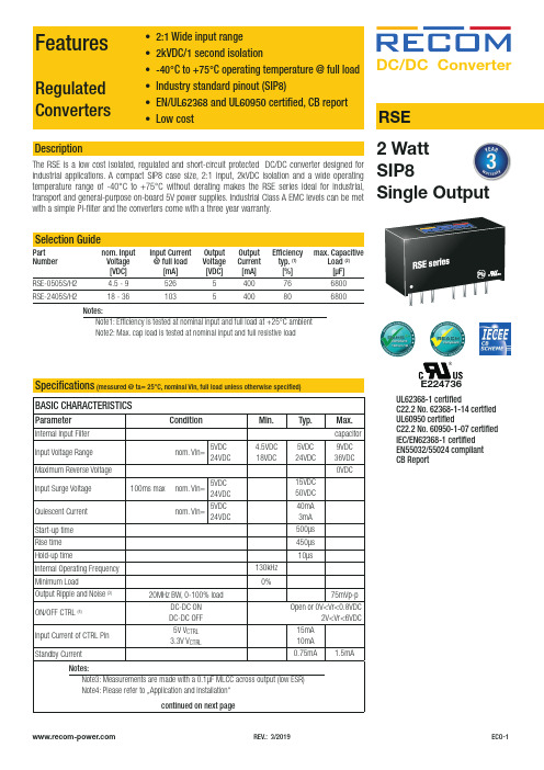
REV.: 3/2019ECO-1Regulated • 2:1 Wide input range • 2kVDC/1 Second isolation• -40°C To +75°C Operating temperature @ full load • Industry standard pinout (SIP8)• EN/UL62368 and UL60950 certified, CB report • Low cost RSEDescriptionThe RSE is a low cost isolated, regulated and short-circuit protected DC/DC converter designed forDC/DC Convert er2 WattE224736UL62368-1 certifiedC22.2 No. 62368-1-14 certfied UL60950 certifiedC22.2 No. 60950-1-07 certified IEC/EN62368-1 certified EN55032/55024 compliant CB ReportFeaturesConverters• 2:1 Wide input range • 2kVDC/1 second isolation -40°C to +75°C operating temperature @ full load • EN/UL62368 and UL60950 certified, CB report • Low costBASIC CHARACTERISTICSParameterCondition Min.Typ.Max.Internal Input Filter capacitor Input Voltage Range nom. Vin=5VDC 24VDC4.5VDC 18VDC5VDC 24VDC9VDC 36VDC Maximum Reverse Voltage 0VDCInput Surge Voltage 100ms max nom. Vin=5VDC 24VDC 15VDC 50VDC Quiescent Current nom. Vin=5VDC 24VDC40mA 3mA Start-up time 500µs Rise time 450µs Hold-up time10µsInternal Operating Frequency 130kHz Minimum Load0%Output Ripple and Noise (3)20MHz BW, 0-100% load75mVp-pON/OFF CTRL (4)DC-DC ON DC-DC OFF Open or 0V<Vr<0.8VDC2V<Vr<6VDC Input Current of CTRL Pin 5V V CTRL 3.3V V CTRL15mA 10mA Standby Current0.75mA1.5mAcontinued on next pageNotes:Note3: Measurements are made with a 0.1µF MLCC across output (low ESR) Note4: Please refer to …Application and Installation“Specifications (measured @ ta= 25°C, nominal Vin, full load unless otherwise specified)REV.: 3/2019ECO-2Specifications (measured @ Ta= 25°C, nominal Vin, full load unless otherwise specified)PROTECTIONSParameterTypeValueShort Circuit Protection (SCP)below 100m Wcontinuous, auto recoveryIsolation Voltage (5)I/P to O/Ptested for 1 second2kVDC Isolation Resistance 1G W min.Isolation Capacitance 100pF max.Insulation Gradefunctionalcontinued on next pageREGULATIONSParameterConditionValueOutput Accuracy 0-100% load ±2.0% max.Line Regulation low line to high line, full load±0.2% max.Load Regulation0% to 100% load±0.5% max.RSE-0505S/H2RSE-2405S/H2Accuracy vs. LoadA c c u r a c y [%]Output Current [A]000.20.10.30.40.50.60.10.20.30.4A c c u r a c y [%]Output Current [A]000.10.20.30.40.50.10.20.30.4REV.: 3/2019ECO-3Specifications (measured @ Ta= 25°C, nominal Vin, full load unless otherwise specified)ENVIRONMENTALParameterConditionValueOperating Temperature Range without derating (see graph)-40°C to +75°CMaximum Case Temperature +105°C Temperature Coefficient ±0.05%/°COperating Altitude 5000mOperating Humidity non-condensing5% - 95% RH max.Pollution Degree PD2MTBF according to MIL-HDBK-217F, G.B.+25°C +75°C2289 x 103 hours 781 x 103 hours VibrationMIL-STD 202G100806040200-4005075100150O u t p u t P o w e r [%]Ambient Temperature [°C]Derating Graph(@ Chamber and natural convection 0.1m/s)SAFETY AND CERTIFICATIONSCertificate Type (Safety)Report / File NumberStandard Information Technology Equipment, General Requirements for Safety E224736-A48UL60950-1, 2nd Edition, 2014CSA C22.2 No. 60950-1-07, 2nd Ed. 2014Audio/Video, information and communication technology equipment - Safety requirementsUL62368-1, 2nd Edition, 2014CSA C22.2 Nr. 62368-1-14, 2nd Ed. 2014Audio/Video, information and communication technology equipment - Safety requirements (CB Scheme)L0339m37-CB-1-B1IEC/EN62368-1, 2nd Edition, 2014RoHS 2+RoHS 2011/65/EU + AM2015/863continued on next pageSpecifications(measured @ Ta= 25°C, nominal Vin, full load unless otherwise specified)DIMENSION and PHYSICAL CHARACTERISTICSParameter Type ValueMaterialcasepottingPCBnon-conductive black plastic (UL94V-0)epoxy (UL94V-0)FR4 (UL94V-0)Dimension (LxWxH)21.8 x 9.2 x 11.1mm Weight 4.7g typ.continued on next pageC3 REV.: 3/2019ECO-4Specifications(measured @ Ta= 25°C, nominal Vin, full load unless otherwise specified)PACKAGING INFORMATIONPackaging Dimension (LxWxH)tube520.0 x 11.2 x 18.2mm Packaging Quantity22pcs Storage Temperature Range-55°C to +125°C Storage Humidity non-condensing5% - 95% RH max.The product information and specifications may be subject to changes even without prior written notice.The product has been designed for various applications; its suitability lies in the responsibility of each customer. The products are not authorized for use in safety-critical applications without RECOM’s explicit written consent. A safety-critical application is an application where a failure may reasonably be expected to endanger or cause loss of life, inflict bodily harm or damage property. The applicant shall indemnify and hold harmless RECOM, its affiliated companies and its representatives against any damage claims in connection with the unauthorizeduse of RECOM products in such safety-critical applications. REV.: 3/2019ECO-5。
EC 30系列电感接触式接近传感器说明书

Specifications are subject to change without notice (15.08.2018)1Housing Rated Mounting Ordering no. Ordering no.diameter operating SCR, cableSCR, plugdist. (S n ) 1)Make & break switching Make & break switching M 30 16 mm Flush (built-in) EC 3016 TBAPL EC 3016 TBAPL-6 M3025 mmNon-flushEC 3025 TBAPLEC 3025 TBAPL-61)Object: Grounded steel plateProduct DescriptionProximity Sensors Capacitive Thermoplastic Polyester Housing Type EC, M30, AC• Featuring TRIPLESHIELD ™Sensor Protection• Rated operational voltage: 20-250 VAC• Adjustable sensing distance 2-16 mm or 4-25 mm • Output: SCR• Make and break switching function • LED indication• High noise immunity• Flush and non-flush types• Plug and Cable versions available • DC versions in the same housingType SelectionCapacitive proximity switch-es with either sensing dis-tance 16 mm flush mount e d or 25 mm sensing distance non-flush mount e d. 2-wire AC output with a switch for choos i ng NO and NCswitch i ng. Grey M30 poly-ester housing with 2 m PVCcable or plug. Ideal for use in level and plas t ic ma c hin-ery applications. Both types are available in metal hous-ings.T R I P L E SH I E L D ™Specifications2Specifications are subject to change without notice (15.08.2018)EC, M30, ACThe environments in which capacitive sensors are install-ed can often be un s table re-garding temperature, humi d ity , object distance and industrial (noise) interference. Because of this, Carlo Ga v azzi offers as standard features in all TRIP L ESHIELD ™ capacitive sensors a user-friendly sensi-tivity adjustment instead of having a fixed sensing range, extend e d sen s ing range todemand i ng are a s, temperature stability to en s ure minimum need for adjusting sensitivity if temperature varies and high immunity to elec t ro m agnetic interference (EMI).Note:(default) to maximum rated sensing range.Adjustment GuideInstallation HintsCapacitive sensors have the unique ability to detect al-most all materials, either in li q uid or solid form. Capa-ci t ive sensors can detect metallic as well as non-me-tallic ob j ects, how e ver, their traditional use is for non-me-tallic materials such as:• Plastic IndustryResins, regrinds or mould-ed products.• Chemical IndustryCleansers, fertilisers, liquid soaps, corrosives and pe -- t r o c hemicals.• Wood IndustrySaw dust, paper products, door and window frames.• Ceramic & Glass I ndustry Raw material, clay or finish e d products, bottles.• Packaging IndustryPackage inspection for lev-el or contents, dry goods, fruits and vegetables, dairy products.Materials are detected due to their dielectric constant. The bigger the size of an object,the higher the density of ma-terial, the better or easier it is to detect the object. Nominal sensing di s tan ce for a capac-itive sensor is refe r e nced to a grounded me t al plate (ST37). For addi t ional information regarding di e lec t ric ratings of materials please re f er to Technical Information.DimensionsT ype A B C D E F SWØ mm mm mm mm mm mm EC 3016TBAPL(-6) M30 x 1.5 x 50 28 50 13.6 15.4 10 36EC 3025TBAPL(-6) M30 x 1.5 x 502862 13.6 15.4 1036Relief of cable strain Protection of the sensing face Switch mounted on mobile carrierTo avoid interference from inductive voltage/current peaks, separate the prox. switch power cables from any other power cables, e.g. motor, contactor or solenoid cablesIncorrectCorrectThe cable should not be pulledA proximity switch should not serve as mechanical stopAny repetitive flexing of the cable should be avoidedSpecifications are subject to change without notice (15.08.2018)3Wiring DiagramDelivery Contents• Capacitive switch: EC 30.. TBAPL(-6)• Screw driver • 2 nuts• Packaging: Cardboard box•Installation & Adjustment Guide (MAN CAP ENG/GER)Accessories• Plugs CONH6A.. serie.EC, M30, AC。
- 1、下载文档前请自行甄别文档内容的完整性,平台不提供额外的编辑、内容补充、找答案等附加服务。
- 2、"仅部分预览"的文档,不可在线预览部分如存在完整性等问题,可反馈申请退款(可完整预览的文档不适用该条件!)。
- 3、如文档侵犯您的权益,请联系客服反馈,我们会尽快为您处理(人工客服工作时间:9:00-18:30)。
RS-232/RS-422/RS-485
EC7520有源光电隔离型接口转换器
说明书
一、概述
EC7520光电隔离型接口转换器、兼容RS-232C、RS-422、RS-485标准,能够将单端的RS-232信号转换为平衡差分的RS-422或RS-485信号,内置的光电隔离器,能够提供3500V的隔离电压,快速的瞬态电压抑制器(TVS) 可以有效地抑制闪电(Lightning)和ESD,可以有效的防止雷击和共地干扰。
RS-232接口端通过一个DB9母头的连接器与PC、IPC、或手提电脑相连,RS-422、RS-485端通过方便的四位接线端子连接。
由于RS-485支持两线半双工,也就是说RS-485仅有的两条线路即要发送数据也要接收数据,握手信号(如RTS,Request To Send)通常去控制数据发送的方向,EC7520光电隔离型接口转换器内部电路能够自动感知数据流方向,并且自动的切换使能控制,可以方便的组成一个RS-485网络而不需任何握手信号,这种RS-485使能控制是完全透明的,不需要对以前的基于RS-232的工作方式作任何软件的修改。
EC7520光电隔离型接口转换器可以为点到点、点到多点的通信提供可靠的连接,点到多点可允许连接32个RS-422或RS-485接口设备,数据通讯速率从0-115.2KBPS,双色数据流量指示灯可指示故障情况、支持的通讯方式有RS-232C到RS-422、RS-232到RS-485转换。
二、性能参数
1、接口特性:接口兼容EIA/TIA的RS-232C、RS- 485/RS-422标准
2、供电电压:DC9-36V
3、电气接口:RS-232C接口DB9孔型连接器、RS-422/RS-485接口四位接线端子、电源接口两位接线端子
4、传输介质:双绞线或屏蔽线
5、工作方式:异步半双工或异步全双工
6、信号指示:三个信号指示灯指示TXD、RXD及POWER
7、隔离度:隔离电压3500VRMS、500VDC连续
8、传输速率:115.2K BPS到300M
38.4K BPS到2.4KM
9600 BPS 到5KM
9、保护等级:RS-232接口+15KV ESD保护,RS-422、RS-485接口每线600W的雷击浪涌保护
10、传输距离:0-5公里(115200-300BPS)
11、尺寸:115mmx72mmx25mm
12、使用环境:-25℃到70℃,相对湿度为5%到95%
三、连接器和信号
1、RS-232C引脚定义
2、。