RH792A 原厂规格书
Parker 792TC和792ST高压管道和79系列单体套接件数据手册说明书

Parker 792TC and 792ST High Pressure Hoses and 79 Series Monoblok ™FittingsBulletin No.4480-B792-US September, 2001One-piece79 Series Monoblok ªfitting has no brazed joints, no potential leak pathsExtra-long socket grips a larger area of the hose endSix spirals of high-tensile steel wire for 6,000 psi constant working pressure in all sizesHigh Nitrile inner tube for exceptional hydraulic fluid compatibilityParker 792TC and 792ST hoses exceed SAE 100R15 specificationAvailable with Tough Cover (TC) or Super Tough (ST) cover We Keep Ideas Flowing ™Parker 792TC and 792ST:The High Pressure PerformersWhen the big pressure is on, specify Parker 792TC or 792ST hose.Six spirals ofhigh-tensile steel wire reinforcement make these the ideal hoses for hydrostatictransmissions, power units, injection molding, test stands, mining equipment, and more.Parker Hannifin CorporationHose Products Division30240 Lakeland Blvd., Wickliffe, Ohio 44092Phone:(440) 943-5700Fax:(440) 943-3129Bul.4480-B792-US GL 7.5M 9/01 ©2001 Parker Hannifin CorporationDANGERFAILURE OR IMPROPER SELECTION OR IMPROPER USE OF THE PRODUCTS AND/OR SYSTEMS DESCRIBED HEREIN OR RELA TED ITEMS CAN CAUSE DEA TH,PERSONAL INJURY AND PROPERTY DAMAGE.B efore selecting or using any Parker hose or fittings or related accessories, it is important thatyou read and follow Parker Safety Guide for Selecting and Using Hoses, Fittings, and RelatedAccessories (Parker Publication No.4400-B.1).!Distributed by:for a superiorcoupling. Features• Parker 792TC comes with our T oughCover (TC) compound, while 792STfeatures our Super T ough (ST) coverfor the ultimate in abrasion resistance• High Nitrile inner tube providesexceptional hydraulic fluid compatibility• 6,000 psi constant working pressurein all sizes• Exceeds SAE 100R15 specification• No-Skive design eliminates the needto remove hose cover before crimping• Highly visible yellow laylinehelps easily identify hoseConstruction792TC hose features an oil-resistanthigh Nitrile rubber inner tube;six spiralsof high-tensile steel wire reinforcement;oil-, weather-, and abrasion-resistantMSHA-accepted black syntheticrubber cover.792ST features thesame construction except for a highabrasion-resistant Super Toughpolymeric cover.Application andtemperature range• Petroleum-base hydraulic fluids andlubrication oils within a temperaturerange of -40˚F to +257˚F(-40˚C to +125˚C)• Polyol ester fluids up to +150°F (+65°C)• Water, water/oil, and water/glycolemulsion hydraulic fluidsup to +185˚F (+85˚C)• Air up to +158˚F (+70˚C);for airabove 250 psi (1,7 MPa), thecover should be pin prickedParkrimp 79 Series fittings See Catalog 4400 for assembly instructions to attach fittings to e Parkrimp 79 Series fittings ONL Y.。
单节 双节线性锂电池充电芯片 规格书

单节/双节线性锂电池充电芯片规格书1、HT6292功能简述1.1、特性● 完全的单节/两节锂离子/锂聚合物电池充电芯片● 极低的热消耗● 集成MOSFET、内置电流检测● 不需要外接反相保护二极管● 0.8%的充电电压精度● 可编程充电电流控制,最大达600mA● 芯片温度热折返保护● NTC 热敏接口监测电池温度● 有无电池检测● LED充电状态指示● 恒压充电电压值可通过外接电阻微调● 可以配置为单节或双节锂电池充电● 短路检测、保护● USB与AC适配器电压输入可选择● 工作环境温度范围:-30℃~70℃● 小型SSOP-16封装1.2、应用● 手持设备,包括医疗手持设备● PDA,移动蜂窝电话及智能手机● 移动仪器,MP3● 自充电电池组● 独立充电器● USB总线供电充电器1.3、概述HT6292为线性锂离子/锂聚合物电池充电芯片,其最低输入电压可低至3.6伏,最大充电电流可达600mA。
HT6292能够编程设计适应各种AC适配器及USB接口。
电池充电分为恒流(CC/Constant Current)、恒压(CV/Constant Voltage)过程,恒流充电电流通过外部电阻决定,最大为600mA。
如果考虑到热扩散问题时,往往使用限流输出的AC适配器,使用HT6292 则可以兼顾线性充电器、开关型充电的优点:充电快,自耗功率小。
HT6292 集成电流热折返保护电路、短路保护,确保充电芯片安全工作。
HT6292可以检测电池是否过放电,并对过放电的电池进行预充电。
HT6292集成NTC热敏电阻接口,可以采集、处理电池的温度信息,保证充电电池的安全工作温度。
HT6292 采用SSOP-16封装。
2、HT6292功能框图图1、HT6292功能框图3、 管脚定义图2、HT6292管脚分布图表1、HT6292管脚描述序号 符号 I/O 描述1 VTRIM - 外接电阻微调满充电压 2&3 VIN I 输入电源4CELLI0:两节锂电池充电 1或悬空:单节锂电池充电5 GND - 地6PDNI芯片使能输入: 0:芯片不工作 1或悬空:芯片工作7TOENI0:取消充电时间限制1或悬空:使能内部充电时间限制8 FAULT O FAULT(GREEN)STATUS(RED)描述0 0 没有充电或者无电池 0 1 正在充电 1 0 充电完成 0 PULSE1 故障状态 9STATUSOPULSE2电池温度异常10 CREF - 振荡器外接电容,决定内部振荡频率,同时提供参考时钟 11 TEMP I 温度传感信号输入12 V33 O 输出3.3V 参考电压,提供10mA 驱动能力 13VSELI0:USB 输入,充电电流为适配器输入时的50% 1或悬空:适配器输入14 RREF - 外接电阻控制恒流充电电流 15&16 VOUTO输出,接锂电池4、HT6292电气特性和推荐工作条件表2、HT6292推荐工作条件参数 最小值 典型值 最大值单位备注电源电压 4.5 5.0 6.5 V 单节电池充电电源电压8.8 10.0 11 V 双节电池充电环境温度-20 70 ℃5、HT6292性能参数表3、HT6292性能参数(一节电池,Ta=25℃)参数 符号 测试条件 最小 典型 最大 单位 上电复位电压上电复位 VPOR 3.6 V Standby模式VOUT漏电流 VBAT=3.7V 20 uA VIN电源电流VOUT悬空、PDN=0 100 uAVOUT悬空、PDN=1或悬空 1 mA 电压调整输出电压 4.158 4.20 4.242 V Dropout电压 200 mV 充电电流恒流充电电流A Icc VRREF>1.3V、VBAT=3.7V540 600 660 mA 预充电电流A Ipre VRREF>1.3V、VBAT=2.0V75 mA 恒流充电电流B Icc VRREF<0.4V、VBAT=3.7V100 mA 预充电电流B Ipre VRREF<0.4V、VBAT=2.0V12 mA 恒流充电电流C Icc RREF=35K、VBAT=3.7V 600 mA 预充电电流C Ipre RREF=35K、VBAT=2.0V 75 mA 再充电、预充电电压预充电阈值电压 Vpre 2.7 2.8 3.0 V 再充电阈值电压 Vrhg 3.95 V 温度监测低温阈值电压高温阈值电压折返阈值 85 100 115 ℃ 折返电流增益 100 mA/℃ 振荡器振荡频率 CREF=20nF 333 Hz 振荡周期 CREF=20nF 2.4 3.0 3.6 mS 逻辑电平逻辑高电平 VH 2 V 逻辑低电平 VL 0.8 V STATUS/FAULT驱动电流 5 mA表4、HT6292性能参数(双节电池,Ta=25℃)参数 符号 测试条件 最小 典型 最大 单位 上电复位电压上电复位 VPOR 6.4 V Standby模式VOUT漏电流 VBAT=7.4V 40 uA VIN电源电流VOUT悬空、PDN=0 100 uAVOUT悬空、PDN=1或悬空 1 mA 电压调整输出电压 8.316 8.40 8.484 V Dropout电压 200 mV 充电电流恒流充电电流A Icc VRREF>1.3V、VBAT=7.4V540 600 660 mA 预充电电流A Ipre VRREF>1.3V、VBAT=4.0V75 mA 恒流充电电流B Icc VRREF<0.4V、VBAT=7.4V100 mA 预充电电流B Ipre VRREF<0.4V、VBAT=4.0V12 mA 恒流充电电流C Icc RREF=35K、VBAT=7.4V 600 mA 预充电电流C Ipre RREF=35K、VBAT=4.0V 75 mA 再充电、预充电电压预充电阈值电压 Vpre 5.4 5.6 6.0 V 再充电阈值电压 Vrhg 7.9 V 温度监测低温阈值电压高温阈值电压折返阈值 85 100 115 ℃ 折返电流增益 100 mA/℃ 振荡器振荡频率 CREF=20nF 333 Hz 振荡周期 CREF=20nF 2.4 3.0 3.6 mS 逻辑电平逻辑高电平 VH 4 V 逻辑低电平 VL 0.4 V STATUS/FAULT驱动电流 5 mA6、HT6292功能描述及管脚应用说明6.1、锂电池充电介绍图3、锂电池充电曲线示意图锂电池充电过程主要分为恒流充电和恒压充电,恒流充电阶段充电电流保持恒定,同时电池电压不断上升。
ELAN EM78F811N 8位微控制器 产品规格书说明书
产品规格书版本1.5义隆电子股份有限公司2021.07商标告之:IBM 为一个注册商标,PS/2是IBM 的商标之一。
Windows 是微软公司的商标。
ELAN 和ELAN 标志是义隆电子股份有限公司的商标。
版权所有 © 2021义隆电子股份有限公司所有权利保留台湾印制本规格书内容如有变动恕不另作通知。
关于该规格书的准确性、适当性或者完整性,义隆电子股份有限公司不承担任何责任。
义隆电子股份有限公司不承诺对本规格书之内容及信息有更新及校正之义务。
本规格书的内容及信息将为符合确认之指示而变更。
在任何情况下,义隆电子股份有限公司对本规格书中的信息或内容的错误、遗漏,或者其它不准确性不承担任何责任。
由于使用本规格书中的信息或内容而导致的直接,间接,特别附随的或结果的损害,义隆电子股份有限公司没有义务负责。
本规格书中提到的软件(如果有),都是依据授权或保密合约所合法提供的,并且只能在这些合约的许可条件下使用或者复制。
义隆电子股份有限公司的产品不是专门设计来应用于生命维持的用具,装置或者系统。
义隆电子股份有限公司的产品不支持而且禁止在这些方面的应用。
未经义隆电子股份有限公司书面同意,任何个人或公司不得以任何形式或方式对本规格书的内容之任一部分进行复制或传输。
义隆电子股份有限公司 总公司:地址: 30076新竹科学工业园区创新一路12号电话: +886 3 563-9977 传真: +886 3 563-9966 *****************.tw http :// 香港分公司:义隆电子(香港)股份有限公司 地址:九龙观塘巧明街95号世达 中心19楼A 室电话: +852 2723-3376 传真: +852 2723-7780美国:Elan InformationTechnology Group (U.S.A.) 地址: 10268 Bandley Drive Suite 101 , Cupertino , CA 95014,USA 电话: +1 408 366-8225 传真: +1 408 366-8225深圳分公司:义隆电子(深圳)有限公司地址:518057深圳市南山区高新技术产业园南区高新南六道迈科龙大厦8A电话: +86 755 2601-0565 传真: +86 755 2601-0500 ******************.cn上海分公司:义隆电子(上海)有限公司地址:上海市浦东新区盛荣路88弄3号703室(盛大天地源创谷内)电话:+86 21 5080-3866 ******************.cn目录目录1 综述 (1)2 特性 (1)3 引脚配置 (2)3.1 10-Pin MSOP (2)3.2 16-Pin DIP/SOP (2)3.3 14-Pin SOP (2)4 引脚描述 (3)5 系统概述 (5)5.1 内存图 (5)5.2 模块图 (6)6 功能描述 (7)6.1 操作寄存器 (7)6.1.1 R0:IAR (间接寻址寄存器) (7)6.1.2 R1 :TCC(定时器时钟) (7)6.1.3 R2:PC (程序计数器和堆栈) (7)6.1.4 R3 :SR(状态寄存器) (10)6.1.5 R4 :RSR(RAM选择寄存器) (10)6.1.6 Bank 0 R5 ~ R6, R8 (Port 5 ~ Port 6, Port 8) (10)6.1.7 Bank 0 R9:TBLP (指令TBRD表指针寄存器) (11)6.1.8 Bank 0 RA:WUPC (唤醒控制寄存器) (11)6.1.9 Bank 0 RB:EECR (EEPROM控制寄存器) (12)6.1.10 Bank 0 RC: EEPA (128 字节 EEPROM 地址) (12)6.1.11 Bank 0 RD: EEPD (128字节EEPROM 数据) (12)6.1.12 Bank 0 RE: OMCR (模式选择寄存器) (12)6.1.13 Bank 0 RF: ISR1 (中断状态寄存器 1) (15)6.1.14 R10 ~ R3F (15)6.1.15 Bank 1 R5~R7 (16)6.1.16 Bank 1 R8 (IRC 选择寄存器) (16)6.1.17 Bank 1 R9: TM1CR1 (定时器/计数器 1控制寄存器1) (16)6.1.18 Bank 1 RA: TM1CR2(定时器/计数器 1控制寄存器 2) (17)6.1.19 Bank 1 RB: TM1DAH (定时器/计数器 1数据缓冲A高字节) (18)6.1.20 Bank 1 RC: TM1DAL (定时器/计数器 1数据缓冲A低字节) (18)6.1.21 Bank 1 RD: TM1DBH (定时器/计数器 1数据缓冲B高字节) (18)6.1.22 Bank 1 RE: TM1DBL (定时器/计数器 1数据缓冲B低字节) (18)6.1.23 Bank 1 RF: ISR2 (中断状态寄存器 2) (19)6.1.24 Bank 2 R5:AISR (ADC输入选择寄存器) (19)6.1.25 Bank 2 R6: ADCON (A/D控制寄存器) (20)6.1.26 Bank 2 R7: ADCON2 (A/D控制寄存器2) (21)6.1.27 Bank 2 R8 : ADDH (AD高 8位数据缓存) (22)6.1.28 Bank 2 R9 : ADDL (AD低4位数据缓存) (22)6.1.29 Bank 2 RA: URCR (UART控制寄存器) (22)6.1.30 Bank 2 RB: URS (UART 状态寄存器) (23)6.1.31 Bank 2 RC: URTD (UART 发送数据缓冲寄存器) (24)6.1.32 Bank 2 RD: URRDL (UART 接收数据低位缓冲寄存器) (24)目录6.1.33 Bank 2 RE: URRDH (UART 接收数据高位缓冲寄存器) (24)6.1.34 Bank 2 RF (24)6.1.35 Bank 3 R5 (24)6.1.36 Bank 3 R6 : TBHP(指令TBRD的表指针寄存器) (24)6.1.37 Bank 3 R7: CMP2CON(比较器2控制寄存器) (25)6.1.38 Bank 3 R8 ~ RC (25)6.1.39 Bank 3 RD :TC3CR (定时器3控制) (25)6.1.40 Bank 3 RE :TC3D (定时器 3 数据缓存) (27)6.1.41 Bank 3 RF (27)6.2 特殊功能寄存器 (28)6.2.1 A (累加器) (28)6.2.2 CONT (控制寄存器) (28)6.2.3 IOC5 ~ IOC6, IOC8 (I/O端口控制寄存器) (28)6.2.4 IOC7, IOC9 (28)6.2.5 IOCA:WDTCR (WDT 控制寄存器) (29)6.2.6 IOCB: P6PDCR (下拉控制寄存器2) (29)6.2.7 IOCC: P6ODCR (漏极开路控制寄存器) (30)6.2.8 IOCD: P9PHCR (上拉控制寄存器2) (30)6.2.9 IOCE:IMR2 (中断屏蔽寄存器2) (31)6.2.10 IOCF: IMR1(中断屏蔽寄存器1) (31)6.3 TCC/WDT 与预分频器 (33)6.4 I/O 端口 (34)6.4.1 使用端口6输入状态改变唤醒/中断功能 (36)6.5 复位和唤醒 (37)6.5.1 复位 (37)6.5.2 总结唤醒和中断模式操作 (39)6.5.3 寄存器初始值的总结 (42)6.5.4 状态寄存器的T和P状态 (49)6.6 中断 (50)6.7 数据EEPROM (52)6.7.1 数据EEPROM控制寄存器 (52)6.7.2 编程步骤 / 举例示范 (52)6.8 模拟数字转换器(ADC) (53)6.8.1 A/D 取样时间 (53)6.8.2 A/D 转换时间 (54)6.8.3 睡眠期间的A/D转换 (54)6.8.4 编程步骤/注意事项 (55)6.9 定时器/计数器1 (TM1) (58)6.9.1 定时器/计数器模式 (58)6.9.2 窗口模式 (59)6.9.3 捕捉模式 (60)6.9.4 可编程分频输出模式和脉冲宽度调制模式 (62)6.9.5 蜂鸣器 (63)6.10 定时器/计数器3 (63)6.11 UART (65)6.11.1 UART 模式 (66)6.11.2 发送 (67)目录6.11.3 接收 (67)6.11.4 波特率发生器 (68)6.11 .5 UART 时序 (68)6.12 比较器 (69)6.12.1 外部参考信号 (69)6.12.2 内部参考电压 (70)6.12.3 比较器输出 (70)6.12.4 中断 (70)6.12.5 从睡眠至唤醒 (70)6.12.6 比较器初始化步骤 (71)6.13 振荡器 (71)6.13.1 振荡模式 (71)6.13.2 晶振 / 陶瓷谐振器(晶体) (72)6.13.3 外部RC振荡模式 (73)6.13.4 内部 RC 振荡模式 (74)6.14 代码选项寄存器 (75)6.14.1 代码选项寄存器 (Word 0) (75)6.14.2 代码选项寄存器(Word 1) (77)6.14.3 客户ID寄存器(Word 2) (78)6.15 上电注意事项 (79)6.16 外部上电复位电路 (79)6.17 残留电压保护 (80)6.18 指令集 (81)7片上调试系统(OCDS) (84)7.1 片上调试的限制 (84)8 时序图 (85)9 绝对最大额定参数 (86)10 DC电气特性 (87)11 AC电气特性 (92)A 编码与制造信息 (93)B 封装类型 (94)C 封装结构 (95)C.1 EM78F811NMS10 (95)C.2 EM78F811NSO14 (96)C.3 EM78F811NAD16 (97)C.4 EM78F811NASO16A (98)D 品质保证和可靠性 (99)D.1 地址缺陷检测 (99)目录规格修订历史目录用户应用注意事项(使用此IC前,应注意如下描述的注意事项,它包含重要信息)1. 如果IRC频率从A频率变为B频率,MCU需要等待一些时间才可以工作。
PC792A1CP-12SR中文资料
Enclosure C: Dust Cover, S: Sealed Case
Parallel Component Nil: None; D: Diode; R: Resistor; N: Nickle Plated Terminals
PC792A Rev C 3-7-06
3220 Commander Drive, Suite 102, Carrollton, Texas 75006 Sales: Call Toll Free (888)997-3933 Fax (818) 342-5296 email: pickerwest@ URL:
PAGE 1
元器件交易网
Temperature Rise C Coil Temperature Rise C Switching Current (Amps)
o o
PC792A
REFERENCE CURVES
100 95 90 85 80 75 70 65 60 55 50 11
元器件交易网
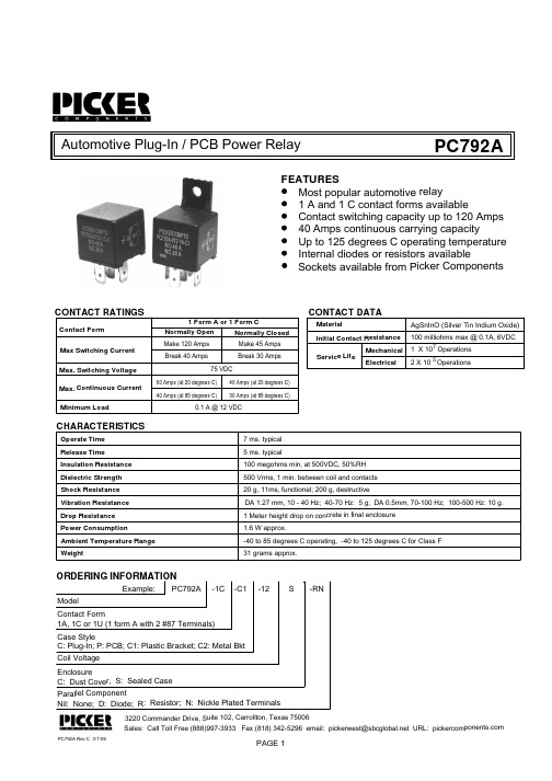
Automotive Plug-In / PCB Power Relay
PC792A
FEATURES Most popular automotive relay 1 A and 1 C contact forms available Contact switching capacity up to 120 Amps 40 Amps continuous carrying capacity Up to 125 degrees C operating temperature Internal diodes or resistors available Sockets available from Picker Components
HT7050a规格书
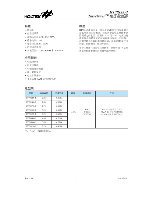
Rev. 1.4012014-03-19• 低功耗• 低温度系数• 高输入电压范围 (高达 30V)• 静态电流:3µA • 输出电压精度:±1%• 内建迟滞电路• 封装类型:TO92, SOT89 和 SOT23-5应用领域• 电池检测器• 电平选择器• 电源故障检测器• 微计算机复位• 电池存储备份• 非易失性RAM 信号存储保护HT70xxA-2系列是一组采用CMOS 技术实现的三端低功耗电压检测器。
该系列中的电压检测器能检测固定的电压,范围从 2.2V 到 8.2V 。
电压检测器系列由高精度低功耗的标准电压源、比较器、迟滞电路以及输出驱动器组成。
采用 CMOS 技术制造,因而确保了低功率消耗。
尽管主要用作固定电压检测器,但这些 IC 可搭配外部元件用于指定的阈值电压的检测。
选型表注:“xx ” 代表检测电压。
Rev. 1.4022014-03-19deN 沟道开漏输出(常开,低有效)输出表格和曲线图...d...引脚图电源供应电压 .............................................................................................................................V SS-0.3V ~ V SS+33V 输出电压 ...................................................................................................................................V SS-0.3V ~ V DD+0.3V 输出电流 .............................................................................................................................................................50mA功耗 ..................................................................................................................................................................200mW 储存温度范围 ............................................................................................................................................................−50°C ~ 125°C 工作环境温度 ........................................................................................................................................−40°C ~ 85°C 注:这里只强调额定功率,超过极限参数所规定的范围将对芯片造成损害,无法预期芯片在上述标示范围外的工作状态,而且若长期在标示范围外的条件下工作,可能影响芯片的可靠性。
珠海奥仕兰电子有限公司质量手册(doc 65页)

珠海奥仕兰电子有限公司质量手册(doc 65页)珠海奥仕兰电子有限公司==================== 质量手册QUALITY MANUAL (依据QS-9000质量管理体系要求国际标准)文件编号Q-001版本号A受控号生效日期2007.10.01制订日期审批日期珠海奥仕兰电子文件编号Q-001版本号 A绪论:公司简介与适用范围发行日期2007.10.1页次 1一、公司简介珠海奥仕兰电子有限公司是一家电子线路板加工及电子产品研发型的股份制企业,位于东海之宾宁波——它是浙江沿海交通枢纽,集水、陆、空运输的网络中心。
公司现有高级管理人员和工程技术人员近20人,员工近200人。
拥有完善的生产、试制、检测手段和设备,公司具有强大的产品研发能力,拥有一支高素质、向效率的研发团队和管理团队。
我公司创建于1999年,是珠海最早的外协PCBA加工企业之一,多年来开发了各类品种、规格的气门嘴系列,生产能力达4000万套,1998年技改项目后开发出汽车、摩托车的消声器、尾管、轮锁和汽车紧固件等系列产品,部分产品远销美、英、法、意大利、德国及中东、日本、新加坡、港台等国家和地区。
公司产品按中中华人民共和国家标准和客户指定的国际行业标准生产。
本公司将全面贯彻ISO9001/QS9000标准,进一步完善质量管理体系,实现公司一贯坚持“质量第一、诚信为本、客户至上、精益求精”的质量方针,使公司的企业管理和产品质量登上新台阶,与国际接轨。
本公司以“今天的质量、明天的效益”为口号,本着“质量第一、客户至上”的宗旨,竭诚为广大客户服务。
二、适用范围本手册的内容与规定事项适用于本公司所属产品SM-006尾管,从订单、采购、生产至交货等为止的活动。
珠海奥仕兰电子文件编号Q-001版本号 A绪论:组织与职责发行日期2007.10.1一、组织机构图:董事会总经理副总经理管理者代表生产 部工程 部质 检 部供 应 部营销 部办 公 室财务 部SMT 车间DIP 车 间 维修 车 间 工 艺 技 术 样 品 试 制 QA 检 验 QC IQC OQC IPQ C采 购 部仓 库 外 贸 内 销 人 事 文控珠海奥仕兰电子文件编号Q-001版本号 A绪论:组织与职责发行日期2001.08.20页次 3一、职责:1.总经理职责1.1认真贯彻执行国家的政策、法规,执行董事会的决议,全面负责公司的经营管理;1.2负责制定长期发展规划,确定质量方针与目标,并在全公司贯彻实施;1.3确定管理者代表、组织、编制和批准、颁发质量手册,并督促实施;1.4确定公司组织机构,明确各部门的职能,各级主管的职责和权限;1.5主持管理评审,对管理执行工作和验证活动提供配备充分的资源,确保质量体系的适用性和持续、有效地运行;1.6领导业务部、供应部做好供销、开拓市场、适应市场等经营策略,负责财务预决算工作的审核;1.7负责仲裁和解决重大的质量问题,实施质量奖惩与质量否决权。
FN I O Module商品说明说明书
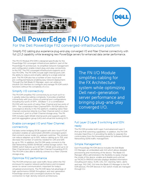
The FN I/O Module (FN IOM) is designed specifically for the PowerEdge FX2 converged-infrastructure platform, part of the PowerEdge FX architecture. Its simplified network management and configuration enable instant plug-and-play connectivityto the FX2. The FX2 converged infrastructure supports up to two FN IOMs. The FN IOMs include eight internal ports with the ability to reduce and simplify cabling to a single external port. The FN IOM also has a number of zero-touch andpre-configured features enabling easy network deployment. Through the Dell Blade IO Manager, users can utilize an intuitive GUI interface to configure and manage FN IOM switch functions without the complexity of a CLI.Simplify I/O connectivityThe FN IOM simplifies FX2 connectivity by as much as 8-to-1, greatly reducing cabling complexity. It provides simplified connectivity with your choice of external port configurations including four ports of SFP+, 10GBase-T, or a combinationFN IOM with two ports of native Fiber Channel and two ports of SFP+. The combination Fiber Channel/SFP+ FN IOM allows for convergence directly in the FX2 platform, enabling native Fiber Channel connection directly to a Fiber Channel switch or direct connection F_port to a Fiber Channel storage array. The FN IOM includes eight 10GbE internal ports and supports uplink-port link aggregation group (LAG) and virtual link trunking (VLT).Enable converged I/O and Fiber Channel connectivityFull data center bridging (DCB) support with zero-touch FCoE activation enables an automated LAN/SAN converged system that connects server nodes to upstream switches. The solution can reduce adapters up to 50%, reduce cabling up to 75%, and decrease the number of switches needed for LAN and SANby up to 75%. In addition, the FN IOM easily connects to the Dell Networking S5000 10/40GbE unified storage switch. The S5000 switch features up to 64 SFP+ 10GbE ports and up to 12 Fiber Channel ports, providing Fiber Channel Forwarding (FCF). The FN IOM is also able to directly connect to a Fiber Channel storage array.Optimize FX2 performanceThe FN IOM enhances east-west traffic flows within the FX2 enclosure for superior network performance and increased server-to-server communication, important for today’s virtualized environments. The FN IOM takes full advantage of high-performance 10GbE throughput, and next-generation PowerEdge servers and converged solutions for easy connection to high-density network architectures.Full Layer 2/Layer 3 switching and SDN readyThe FN IOM provides both Layer 2 and advanced Layer 3IPv4 and IPv6 switching capabilities. In addition, the FN IOM includes OpenFlow 1.3, providing the ability to separate the control plane from the forwarding plane for Software Defined Networking (SDN) traffic management.Simple Management:Each PowerEdge FN IOM device includes the Dell BladeI/O Manager, an embedded web GUI which allows detailed provisioning and monitoring of the device. The Blade I/O Manager offers administrators the flexibility to easily change the mode of the device, enable and disable ports and setup TACACS+/RADIUS and also displays detailed information including port status, VLAN, LAG, VLT, stacking, fabric, alerts and logs. FX2 CMC GUI links the Blade I/O Manager to the FN IOM devices. FN IOM devices in full-switch mode are managed through CLI.The FN I/O Module simplifies cabling forthe FX Architecture system while optimizing Dell next-generation server performance and bringing plug-and-play converged I/O.Dell PowerEdge FN I/O ModuleFor the Dell PowerEdge FX2 converged-infrastructure platform Simplify FX2 cabling plus experience plug-and-play converged I/O and Fiber Channel connectivity with full L2/L3 capability while leveraging new PowerEdge servers for enhanced data center performance.Two native Fiber Channel ports and two SFP+ portsFour SFP+ ports with rebootFiber Channel NPIV Proxy Gateway* (NPG) with gateway capabilities to existing SAN fabricsF-port capability providing Fiber Channel fabric services allowing direct connection to a Fiber Channel storage Four SFP+ portsSupports optical and DAC cablemediaFour 10GBASE-T portsSupports copper media up to 100m*The Dell PowerEdge FN2210S I/O Module has 2 FC ports and 2 Ethernet ports. The Ethernet ports allow connectivity to LAN and the FC ports support NPG (NPIV Proxy Gateway) mode to connect to SAN switch.**The FN2210S supports F-port capability that enables direct connection to Fiber Channel storage arrays without the need to connect through a Fiber Channel switch.Specifications: Dell PowerEdge FN I/O ModuleDell FN I/O ModuleFN2210S, 2 line-rate fixed 2/4/8Gb Fiber Channel ports with 2 line-rate 1GbE/10GbE SFP+ ports (Default Mode) or 4 line-rate fixed 1GbE/10GbE SFP+ ports (Ethernet Mode)FN410S, 4 line-rate fixed 1GbE/10GbE SFP+ portsFN410T, 4 line-rate fixed 100Mb/1Gb/10Gb BASE-T ports (supports auto negotiation)OpticsT ransceiver, SFP+, 10GbE, SR, 850nm Wavelength, 300m ReachT ransceiver, SFP+, 10GbE, LR, 1310nm Wavelength, 10km ReachT ransceiver, SFP+, 10GbE, DWDM, ITU Channel 17–61, 40km Reach T ransceiver, SFP, 1000Base-SX, 850nm Wavelength, 550m ReachT ransceiver, SFP, 1000Base-LX, 1310nm Wavelength, 10km Reach Transceiver, SFP, 1000Base-TCablesCable, 40GbE QSFP+ to 4xSFP+, Direct Attach Breakout Cable, 0.5m, 1m, 3m, 5m, 7m, 10mCable (optics not included)Cable, SFP+, CU, 10GbE, Direct Attach Cable, 0.5m, 1m, 3m,5m, 7m, 10mSoftwareSoftware, Networking, Full-switch mode, FNIOM*Additional port attributes:Up to 8 line-rate 10GbE KR ports1 USB (Type A) port for storage1 USB (Type A) port for console/managementFN I/O Module Modes supported:Standalone mode: I/O aggregation, default automated mode Stacking mode: I/O aggregation while stackedVLT mode: I/O aggregation while VLT’dPMUX mode: I/O aggregation with limited CLIFull-switch mode: L2/L3 switch mode with CLI EnvironmentalMax. thermal output: 214.9 BTU/hMax. current draw per IOM:FN410S: 5.5A @ 12V DCFN410T: 6.5A @ 12V DCFN2210S: 6.6A @ 12V DCMax. power consumption per IOM:FN410S: 66WFN410T: 77WFN2210S: 79WISO 7779 A-weighted sound pressure level:59.6dBA at 73.4°F (23°C)Operating temperature: 32° to 140°F (0° to 60°C)Operating humidity: 10 to 85% (RH), non-condensingMax. non-operating specifications:Storage temperature: –40° to 158°F (–40° to 70°C)Storage humidity: 5 to 95% (RH), non-condensingPerformanceMAC addresses: 64KSwitch fabric capacity: 240Gbps (Full-Duplex)Forwarding capacity: 179MppsLink aggregation:Max 4 members per group and 1 uplink LAG group Indefault mode. Max of 1 LAG group with 12 membersor 12 LAG groups with one member each in case of 6unit stackingIn standalone mode:Max. 4 members per group and 1 uplink LAG group(Port-channel 128 default mode)In stacking mode:Max. of 12 members per group and 1 uplink LAGgroup (only supported in FN410S and FN410T)In Pmux standalone:Max. of 24 LAG groups and multiple uplink LAG groupsIn Pmux stacking mode:Max. of 12 lag groups can be created.In full-switch mode: max. of 24 LAG groups andmultiple uplink LAG groupsQueues per port: 4 queuesVLANs: 4094Line-rate Layer 2 switching: All protocols, includingIPv4Line-rate Layer 3 routing: IPv4 and IPv6Packet buffer memory: 4MBCPU memory: 2GBACLs: Ingress egress in full switch modeVirtual Link Trunking (VLT) and stackingVLT supported in VLT, PMUX and Full-switch modewith FN410S, FN410T, and FN2210SStacking supported in stacking, PMUX and Full-switchmode with FN410S and FN410TStacked units: up to 6 units in ring or daisy chainStackingStacked units: Up to 6 IOMs (using 10GbE portsdeployedvia CLI)Stacking bandwidth: Up to 40Gbps (using 1 x 10GbEring)Stacking topology: Ring and daisy chainVirtual Link Trunking (VLT): mVLT and L2 over VLT(deployed via CLI)VLT suported in VLT, PMUX and Full-switch modeStacking supported in stacking, PMUX and Full-switchmode with FN410S and FN410TDell SKU descriptions*Available with full-switch mode.*Available with full-switch mode.IEEE compliance 802.1AB LLDP802.1p L2 Prioritization 802.2 LLC802.3ab Gigabit Ethernet (1000Base-T)802.3ad Link Aggregation with LACP 802.3ae 10GbE (10GBase-X)802.3u Fast Ethernet (100Base-TX)802.3x Flow Control802.3z Gigabit Ethernet (1000Base-X)ANSI/TIA-1057 LLDP-MED MTU 12KBVLAN and Spanning Tree 802.1Q VLAN Tagging802.3ac Frame extensions for VLAN Tagging Native VLAN802.1D Bridging, STP* 802.1s MSTP* 802.1w RSTP* Force10 PVST+* 2338 VRRP*Layer 3 Routing - full switch mode 1058 RIPv1 2453 RIPv22154 MD5 (OSPF) 1587 NSSA (OSPF) 2328 OSPFv2 2740 OSPFv34222 Prioritization and congestion avoidance 4552 OSPFv3 IPsec authenticationBGP1997 BGP Communities 2385 BGP MD52439 BGP Route Flap Damping 2796 BGP Route Reflection 2918 BGP Route Refresh 3065 BGP Confederations4360 BGP Extended Communities 4893 BGP 4-byte ASN5396 BGP 4-byte ASN representationsdraft-ietf-idr-restart-06 BGP Graceful Restart 1195 Routing IPv4 with IS-IS 5308 Routing IPv6 with IS-ISFCoEINCITS FC-BB-5 Ver 2.00 (FSB, NPIV & F-Port only; FN2210S only)Fibre Channel Generic Services (FC-GS, FC-GS2, GC-GS3; FN2210S only)FC-FG (F_PORT only; FN2210S only)FC-VI (FN2210S only)FCoE Initialization Protocol (FIP) v1FCoE Transit (FIP Snooping Bridge) supported with FN410S, FN410TNative FCoE forwardingNPIV Proxy Gateway (NPG) supported with FN2210S FCoE-FC forwarding / FPORT – Supported only with FN2210SDynamic FCoE to FC Load balancingData Center BridgingIEEE 802.1Qbb Priority-Based Flow Control (PFC)IEEE 802.1Qaz Enhanced Transmission Selection (ETS)Data Center Bridging eXchange (DCBx)DCBx Application TLV (iSCSI, FCoE)Security options 854 Telnet 959 FTP 1321 MD5 1350 TFTP2474 Differentiated Services 2856 RADIUS 3164 Syslog4254 SSHv2draft-grant-tacacs-02 TACACS+ 4807 IPSec SPD MIB 4301 IPSecGeneral IPV4 protocols 768 UDP 791 IPv4 792 ICMP 793 TCP 826 ARP1027 Proxy ARP* 1035 DNS (client)*1042 Ethernet Transmission 1191 Path MTU Discovery* 1305 NTPv3 1519 CIDR1542 BOOTP (relay)* 1812 Routers*1858 IP Fragment Filtering*2131 DHCP (relay, client, server)* 3021 31-bit Prefixes 3046 DHCP Option 82* 3069 Private VLAN*3128 Tiny Fragment Attack ProtectionGeneral IPv6 protocols 2460 IPv6*1858 IP Fragment Filtering* 2461 N eighbor Discovery* 2675 Jumbograms (partial)*3587 Global Unicast Address Format*2462 Stateless Address Autoconfiguration (partial)* 4291 Addressing* 2463 ICMPv6*4861 IPv6 Host for management port 1981 IPv6 Path MTU discovery* Multicast protocols 1112 IGMPv1*3569 SSM for IPv4* 2236 IGMPv2*4541 IGMPv1/v2 Snooping3376 IGMPv3 draft-ietf-pim-sm-v2-SDN/OpenflowOpenflow 1.0 with extensions*Network management 1155 SMIv1*1156 Internet MIB* 1157 SNMPv11212 Concise MIB Definitions* 1215 SNMP Traps* 1493 Bridges MIB* 1850 OSPFv2 MIB*1901 Community-based SNMPv2 2011 IP MIB* 2012 TCP MIB* 2013 UDP MIB*2096 IP Forwarding Table MIB* 2570 SNMPv3*2571 Management Frameworks*2572 Message Processing and Dispatching* 2575 SNMPv3 VACM*2576 Coexistence Between SNMPv1/v2/v3 2578 SMIv2*2579 Textual Conventions for SMIv2*2580 Conformance Statements for SMIv2* 2618 RADIUS Authentication MIB* 2665 Ethernet-like Interfaces MIB*2787 VRRP MIB 2819 RMON MIB (groups 1, 2, 3, 9)* 2863 Interfaces MIB*3273 RMON High Capacity MIB* 3416 SNMPv2 3418 SNMP MIB3434 RMON High Capacity Alarm MIB* ANSI/TIA-1057 LLDP-MED MIB* IEEE 802.1AB LLDP MIB*IEEE 802.1AB LLDP DOT1 MIB* IEEE 802.1AB LLDP DOT3 MIB* sFlowv5*FORCE10-IF-EXTENSION-MIB FORCE10-LINKAGG-MIB*FORCE10-COPY-CONFIG-MIB* FORCE10-MON-MIB*FORCE10-PRODUCTS-MIB* FORCE10-MS-CHASSIS-MIB*FORCE10-SMI FORCE10-SYSTEM-COMPONEN-MIB* FORCE10-TC-MIB*FORCE10-TRAP-ALARM-MIB* FORCE10-FIPSNOOPING-MIB FORCE10-DCB-MIB*LLDP-EXT-DOT1-DCBX-MIB* IEEE8021-PFC-MIB* DELLl_ITA.REV_1_1.MIB F10-JUMPSTART-MIB* IEEE8021-PFC-MIB* DELLl_ITA.REV_1_1.MIB F10-JUMPSTART-MIB* FORCE10-MSTP-MIB* F10-FPSTATS.MIBf10-VirtualLinkTrunk.MIB F10-DCBX.MIBF10-MS-PLATFORM.MIBRegulatory and environment compliance UL/CSA 60950-1, Second Edition EN 60950-1, Second EditionIEC 60950-1, Second Edition Including all National Deviations and Group DifferencesEN 60825-1 Safety of Laser Products Part 1:Equipment Classification Requirements andUser’s Guide Optical Fiber Communication Systems FDA Regulation 21 CFR 1040.10 and 1040.11 EmissionsAustralia/New Zealand: AS/NZS CISPR 22: 2006, Class ACanada: ICES-003, Issue-4, Class AEurope: EN 55022: 2006+A1:2007 (CISPR 22: 2006), Class AJapan: VCCI V3/2009 Class AUSA: FCC CFR 47 Part 15, Subpart B:2009, Class A EN 300 386 V1.4.1:2008 EMC for Network Equipment EN 55024: 1998 + A1: 2001 + A2: 2003EN 61000-3-2: Harmonic Current Emissions EN 61000-3-3: Voltage Fluctuations and Flicker EN 61000-4-2: ESDEN 61000-4-3: Radiated Immunity EN 61000-4-4: EFT EN 61000-4-5: SurgeEN 61000-4-6: Low Frequency Conducted Immunity All components are RoHS compliantLearn More at /Networking© 2016 Dell Inc. All rights reserved. Dell, the DELL logo and the DELL badge are trademarks of Dell Inc. Other trademarks and trade names may be used in this document to refer to either the entities claiming the marks and names or their products. Dell disclaims proprietary interest in the marks and names of others. This document is for informational purposes only. Dell reserves the right to make changes without further notice to products the herein. The content provided is as-is and without expressed or implied warranties of any kind.May 2016 | Version 1.5Dell_Networking_FN IOM_SpecSheetSpecifications: Dell PowerEdge FN I/O Module。
RH6015-C(D)原厂规格书

单通道触摸感应开关RH6015-C(D)规格书Revision2.52019-06-03目录1.简介 (3)2.特点 (3)3.封装引脚示意图及模式 (4)3.1引脚示意图 (4)3.2默认输出模式 (4)4.订购信息 (5)5.功能描述 (5)5.1输出有效电平配置(AHLB) (5)5.2快速/低功耗模式 (6)5.3保持/同步模式(TOG) (6)5.4最大开启时间 (6)6.应用电路图 (6)7.PCB设计注意事项 (7)8.电气参数 (8)8.1最大绝对额定值 (8)8.2DC电气参数 (8)9.封装信息(SOT23-6) (9)10.封装信息(DFN6) (11)1.简介RH6015是一款内置稳压模块的单通道电容式触摸感应控制开关IC,可以替代传统的机械式开关。
RH6015可在有介质(如玻璃、亚克力、塑料、陶瓷等)隔离保护的情况下实现触摸功能,安全性高。
RH6015内置高精度稳压、上电复位、低压复位、硬件去抖、环境自适应算法等多种有效措施,大大提高自身抗干扰性能。
RH6015可通过外部引脚配置成多种工作模式,可广泛应用于灯光控制、电子玩具、消费电子、家用电器等产品中。
RH6015C[A],CMOS输出,SOT23-6封装。
RH6015CL(F),CMOS输出,DFN6封装。
RH6015D[A],NMOS开漏输出,SOP23-6封装。
2.特点∙工作电压:2.3V~5.5V∙最高功耗工作电流5.0uA@3V,低功耗模式工作电流2.5uA@3V∙内置高精度稳压模块∙上电0.5s快速初始化∙环境自适应功能,可快速应对触摸上电等类似应用场景∙可靠的上电复位(POR)及低压复位(LVR)性能∙芯片内置去抖动电路,有效防止由外部噪声干扰导致的误动作∙通过外部引脚配置快速/低功耗模式、同步/保持模式∙可通过外部引脚设置高/低电平有效输出、最大开启时间∙封装:SOT23-6、DFN63.封装引脚示意图及模式3.1引脚示意图图1RH6015C[A]/RH6015D[A](SOT23-6)引脚示意图表图2RH6015CL/RH6015CF(DFN6)引脚示意图表I-P L/I-P H:带内部下拉/上拉电阻的CMOS输入OD:CMOS开漏输出,无保护二极管O:推挽型CMOS输出I/O:CMOS输入/输出P:电源/地3.2默认输出模式可配置:指该封装上有相应模式的配置管脚引出,具体见5.功能描述。
- 1、下载文档前请自行甄别文档内容的完整性,平台不提供额外的编辑、内容补充、找答案等附加服务。
- 2、"仅部分预览"的文档,不可在线预览部分如存在完整性等问题,可反馈申请退款(可完整预览的文档不适用该条件!)。
- 3、如文档侵犯您的权益,请联系客服反馈,我们会尽快为您处理(人工客服工作时间:9:00-18:30)。
支持最大功率为10W/5W的Divider1苹果设备。
5.2 Divider模式设定
定义12W充电器,DP/DM与USB端子D+/D-端连接方式无要求。
湖南融和微电子有限公司
RH792A_SPEC_Ver1.0
4/7页
7/6/2015
6.应用电路图
RH792A_SPEC
USB Connector
5V Power
6°
-
C1
0.03
-
0.13
R
-
<0.2
-
C2
0.60
-
0.70
R1
-
0.08
-
D
0.03
-
0.13
R2
-
0.08
-
注意:
规格如有更新﹐恕不另行通知。请在使用该 IC 前更新规格书至最新版本。
湖南融和微电子有限公司
RH792A_SPEC_Ver1.0
7/7页
7/6/2015
7/6/2015
表 2 引脚描述表 引脚名称
DP1 GND DP2 DM2 VDD DM1 I:CMOS输入 I/O:CMOS输入/输出
RH792A
1 2 3 4 5 6
RH792A_SPEC
I/O
功能描述
I/O 连接至第一组 USB 端口 DP
P
负电源
I/O 连接至第二组 USB 端口 DP
I/O 连接至第二组 USB 端口 DM
2.84 2.84
单位 V V uA uA V V
湖南融和微电子有限公司
RH792A_SPEC_Ver1.0
6/7页
7/6/2015
8.封装信息
8.1 SOT23-6L
RH792A_SPEC
图 4 SOT23-6L封装图
表 7 SOT23-6L封装尺寸
符号
尺寸(mm单位) 最小值 典型值 最大值
符号
NO
USB 充电
1
协议
2
支持
3
4
USB 协议
Divider 3(注 1*) D+/D-置 1.2V BC1.2 DCP CTIS YD/T 1591-2009
USB 端子 D+
2.7 1.2 短接
短接
USB 端子 D-
2.7 1.2 短接
短接
最大 功率
12W
792A
√ √ √ √
注1*:苹果设备的DividerX模式向下兼容DividerX-1模式,既支持最大功率12W的Divider2苹果设备,也
5.1 USB协议支持 ......................................................................................................................... 4 5.2 Divider模式设定...................................................................................................................... 4 6. 应用电路图 .................................................................................................................................... 5 7. 电气参数 ....................................................................................................................................... 5 7.1 最大绝对额定值 ...................................................................................................................... 5 7.2 DC/AC特性............................................................................................................................. 6 8. 封装信息 ....................................................................................................................................... 7 8.1 SOT23-6L .............................................................................................................................. 7
范围 -0.3~5.5 -0.5~VDD +0.5 -20 ~ 85 -50 ~ 125
>8000
单位 V V ℃ ℃ V
湖南融和微电子有限公司
RH792A_SPEC_Ver1.0
5/7页
7/6/2015
7.2 DC/AC特性
表 6 电气参数表
参数
符号
条件
最小值
工作电压
VDD
4.5
LVR电压
VLVR
2
12W(Divider3)
注1*:5W、10W、12W仅针对Apple系列设备区分,各型号对非Apple系列设备的支持无区别;苹果协议
是向下兼容苹果设备的,即设置12W协议时(Divider3),兼容12W/10W/5W的苹果设备。
湖南融和微电子有限公司
RH792A_SPEC_Ver1.0
3/7页
RH792A_SPEC
USB 充电协议端口控制器
RH792A
规格书
Revision 1.0 2015-7-6
湖南融和微电子有限公司
RH792A_SPEC_Ver1.0
1/7页
7/6/2015
RH792A_SPEC
目录
1. 简介 .............................................................................................................................................. 3 2. 特性 .............................................................................................................................................. 3 3. 封装引脚示意图 ............................................................................................................................. 3 4. 定购信息 ....................................................................................................................................... 4 5. 功能描述 ....................................................................................................................................... 4
协议 可靠的上电复位(POR)及低压复位(LVR)性能 封装及脚位绑定:SOT23-6
1 DP1 2 GND 3 DP2
DM1 6 VDD 5 DM2 4
RH792A
图 1 引脚示意图
表 1 产品说明
No. 产品型号
产品封装
协议端口数
支持Apple设备最大功率协议 (注1*)
1
RH792A
SOT23-6L
损坏 IC,主要起限流作用,建议取值 R=750 欧左右;C 主要用来补偿 R 对电源纹波的影响,也可以 不要。
7.电气参数
7.1 最大绝对额定值
表 5 最大绝对额定值
项目 工作电压 输入/输出电压 工作温度 储藏温度 ESD 水平(DP/DM,HBM)
符号 VDD
VI / VO TOPR TSTG VESD
尺寸(mm单位) 最小值 典型值 最大值
A
2.82
-
3.02
D1
0.40
-
0.50
A1
0.90
-
1.00
D2
-
0.254
-
A2
0.35
-
0.45
D3
0.60
-
0.70
B
1.52
-
1.72
θ
-
9°
-
B1
2.80
-
3.00
θ1
-
10°
-
B2
0.119
-
0.135
θ2
C
1.05
-
1.15
θ3
-
0~8°
-
-