基于单片机的汽车转向灯设计单片机课程设计报告
单片机课程设计汽车转向灯的设计
1 绪论…………………………………………………………………………1.1 选题背景……………………………………………………………………… 1.2 研究意义………………………………………………………………………1.3 研究方法……………………………………………………………………2 汽车转向灯单片机控制系统原理………………………………………………2.1 汽车转向灯工作原理…………………………………………2.2 单片机系统的工作原理及设计………………………………………………3 设计方案论证与选择………………………………………………3.1 方案论证一……………………………………………………………3.2 方案论证二…………………………………………………………3.3 方案选择…………………………………………………………4 控制系统的硬件设计…………………………………………………………4.1 单片机控制系统电路图……………………………4.2 单片机控制系统功能模块的设计………………4.3 元器件清单……………………………………………………5 主要芯片介绍…………………………………………………………5.1 单片机的特点………………………………………………………5.2 单片机各引脚介绍………………………………………………………5.3 单片机的功能介绍………………………………………………………6 控制系统的软件设计……………………………………………………7.1 汽车转向灯控制系统流程图7.2 软件和程序设计7 电路功能实现7.1 软件调试7.2 单片机硬件功能实现7.3 仿真操作说明及现象………………………………………………………参考文献…………………………………………………………………………………. 致谢………………………………………………………………………………………附录………………………………………………………………………………………摘要随着单片机的日益发展,其应用也越来越广泛,通过对“汽车转向灯单片机控制系统”设计,可以对单片机的知识得到巩固和扩张。
基于C51单片机汽车转向灯设计
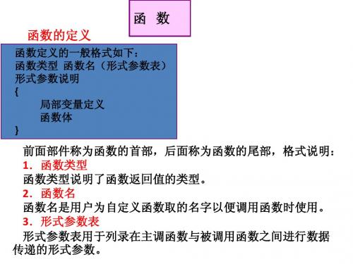
函 数
函数的定义
函数定义的一般格式如下: 函数类型 函数名(形式参数表) 形式参数说明 { 局部变量定义 函数体 }
前面部件称为函数的首部,后面称为函数的尾部,格式说明: 1.函数类型 函数类型说明了函数返回值的类型。 2.函数名 函数名是用户为自定义函数取的名字以便调用函数时使用。 3.形式参数表 形式参数表用于列录在主调函数与被调用函数之间进行数据 传递的形式参数。
例如:下面是定义数组的两个例子。 unsigned char x[5]; unsigned int y[3]={1,2,3}; 第一句定义了一个无符号字符数组,数组名为x,数组中的元素个数 为5。 第二句定义了一个无符号整型数组,数组名为y,数组中元素个数为 3,定义的同时给数组中的三个元素赋初值,赋初值分别为1、2、3。 需要注意的是,C51语言中数组的下标是从0开始的,因此上面第一 句定义的5个元素分别是:x[0]、x[1]、x[2]、x[3]、x[4]。第二句定义的3 个元素分别是:y[0]、y[1]、y[2]。赋值情况为:y[0]=1;y[1]=2;y[2]=3。
C51规定在引用数组时,只能逐个引用数组中的各个元素,而不能一 次引用整个数组。但如果是字符数组则可以一次引用整个数组。
#include<stdio.h> void main() { int i; float data[10],ave,sum=0; for(i=0;i<10;i++) scanf(“%f”,&data[i]); for(i=0;i<10;i++) sum=sum+data[i]; ave=sum/10; for(i=0;i<10;i++) if(data[i]<ave) printf(“%f”,data[i])
基于单片机的汽车转向灯控制系统.doc
基于单片机的汽车转向灯控制系统.微机应用课程设计报告题目: 基于单片机的汽车转向灯控制系统专业:电子信息工程班级:11电信二班姓名:学号: 地点:时间:2014.03.24- 电子信息工程班级:11电信二班姓名:学号: 地点:时间:2014.03.24:摘要本设计主要解决如何更加灵活的汽车尾灯控制器进行控制,左转,右转和急刹车信息等。
通过设计汽车尾灯显示控制电路,能很好的综合运用我们所学到的单片机,C语言,模拟电路知识,熟悉电子电路设计的基本方法。
有多种方法来设计汽车尾灯控制电路,主要是运用单片机的相关知识用硬件来设计制作一个16位汽车尾灯显示控制电路的。
它的特点是电路简单,制作方便,容易操作,可反复擦写,性能可靠。
本设计主要由四部分组成,包括按键电路,LED灯电路,驱动电路,复位电路。
本文介绍了一种以STC89C52单片机为核心的控制电路。
该电路以发光二极管LED灯为显示电路。
汽车的尾灯是其运行方式的最直接表示方式,令行人或其他车辆清晰明白它将要发生的动态变化。
从而避免交通事故的发生。
设计此电路要求严格符合交通规则,尾灯闪亮或熄灭准确,才不会让行人或其他车辆产生误解。
目前在国内外,整个社会的趋势都是低能耗,环保,高效为主题的。
所以LED尾灯是发展的趋势,而且现在部分高档车已经开始配置【关键词】发光二极管单片机设计程序word教育资料引言车灯是行车安全的必备件,除了具有照明作用,对行人和其他车辆还具有转向、刹车等警示作用。
汽车转向和故障信号灯是汽车运动方向和车身状态的表示信号,关系着汽车的安全问题,因此基于单片机的汽车转向灯控制器一直以来都是汽车电子设计中的一个十分重要的领域。
本设计是设计一个单片机控制系统,在汽车进行左转弯、右转弯、刹车、合紧急开关、停靠、倒车等操作时,实现对各种信号指示灯的控制。
它主要是对单片机的并行输入/输出口电路的应用,通过I/O口控制发光二极管的亮﹑灭﹑闪烁,加上一些串口电路﹑按键电路﹑驱动电路来模拟汽车尾灯的功能并在PC机上显示此时的汽车行进状态。
基于单片机的汽车转向灯课程设计报告
单片机原理及系统课程设计专业:班级:姓名:学号:指导教师:兰州交通大学自动化与电气工程学院2010 年 3 月 7 日基于单片机的汽车转向灯设计摘要本设计采用单片机控制,在控制系统中,选择了5个开关、1个AT89C51单片机、7只发光二极管。
其中AT89C51单片机作为控制核心,用5个开关的状态来模拟汽车转弯时相关状态。
用7只发光二极管的明灭来模拟汽车灯在相关信号下的状态。
关键词:单片机;汽车转弯信号灯;AT89C51Abstract:The design uses a single-chip control, select the five switches in the control system, an AT89C51 microcontroller seven light-emitting diodes. AT89C51 microcontroller as con trol core, with the status of the five switches to simulate car turns state. Seven light-emit ting diode Ming off car lights to simulate the state related signals.Key Words: SCM,Automotive turn signal lights ,AT89C511 引言在当今社会,汽车方便了人们的生活,人们也开始了依赖于汽车。
汽车的数量也是越来越多,但是一些交通事故也是越来越多。
所以汽车转向灯也成了汽车必不可少的装备,汽车转向灯可以有效的对行人或者其他车辆起到一定的提示作用。
传统的汽车转向灯由于自身条件的限制,可靠性低,定时时间不够精确,使用寿命较短,且继电器受温度影响较大,对于温度变化较大的环境往往不能满足要求。
2 设计方案及原理2.1设计方案汽车转向灯电路是由单片机AT89C51、LED显示电路、按键电路等几部分构成。
基于单片机的汽车转向灯设计报告
Course Design of Principle and System of Single Chip MicrocomputerDesign of Automobile Turn Signal Based on Single ChipMicrocomputer1 IntroductionIn today's society, science, technology and industry are highly developed, and the number of cars is increasing year by year. Every corner of the street is filled with them, but everything has two sides. Cars bring convenience to people's lives and pose a threat to traffic and personal safety. Therefore, we should take effective measures to reduce the probability of accidents and improve the running efficiency of vehicles. Therefore, the car turn signal becomes an essential device for every car. Car turn signal is a necessary condition for driving safety. Besides lighting, it also has warning functions for pedestrians and other vehicles, such as turning, meeting and braking. Due to the limitation of its own conditions, the traditional automobile turn signal lamp has low reliability, inaccurate timing and short service life, and the relay is greatly affected by the temperature, so it can't meet the requirements for the environment with large temperature changes. Therefore, the design of automobile turn signal in this paper is realized by single chip microcomputer. The single chip microcomputer control system can not only avoid the traditional shortcomings, but also have the advantages of strong function, fle*ible use, high reliability, low cost, small size, control-oriented and intelligent function.2 design scheme and principleThis design requires the control of all kinds of signal indicators when the car is turning left, turning right, braking, turning on the emergency switch, stopping and reversing. According to the design requirements, formulate the overall design idea.The automobile turn signal circuit is composed of AT89C51, reset, alarm, LED display circuit, key circuit and so on.2.1 system designThe MCU AT89C51 is used as the core chip to simulate the automobile turn signal by controlling the display of LED, that is, the switch 1-6 is closed to simulate the operation of braking, emergency, stopping, turning left, turning right and reversing. The on-off display of LED D1-D8 is used to simulate the display of fault indicator, left headlight, right headlight, left turn signal, right turn signal, left tail light, right tail light and back-up light of automobile. When turning, it is required that the two indicator lights on the left and right tail lights and the left and right headlights on the dashboard emit flashing signals accordingly; When the emergency switch is closed, all si* signal lights should flash; When the car brakes, the two tail lights emit steady bright signals; If you brake when you are turning, the signal that should flash when you are turning should still flash. They all flash at low frequency, and any combination of switches other than the above will cause the fault indicator to flash. The flashing frequency is high and an alarm sounds. After pressing the corresponding reset key, the alarm sounds and the indicator lights are released, and then the circuit problems can be checked in time.The system block diagram is shown in Figure 1.Figure 1 System composition block diagram2.2 working principle of single chip microcomputer system2.2.1 switch state detectionSwitch state detection, which is an input relation for AT89C51, can detect the state of each switch in turn, and let the corresponding LED indicate the state of each switch; You can also detect the state of the si*-way switch at one time, that is, read all the states of the P2 port with MOV A and P2 instructions at one time, and take the state of the lower 6 bits to indicate, and select the branch according to this.2.2.2 output controlThe LEDs are indicated by D1-D8, and the design uses the instruction MOV P1, #111*****B method to realize the selection.2.2.3 timerSignal control is the result of the realization of timer. In the control of automobile turning light, the programmable timer of AT89C51 single chip microcomputer is mainly used to realize the delay of light flashing, that is, by counting the system clock pulses, and the count value is set by the program. A timer is used to generate a high-frequency flashing function.2.2.4 circulation systemThe main program loop is achieved through repeated calls and loops of statements, and the low-frequency flashing function is generated.2.2.5 automobile turn signal controlWhen the car is turning, stopping or in an emergency, the flashing frequency of the e*ternal signal lights and the indicator lights of the instrument panel is low frequency signals. When an error occurs, the signal lamp frequency flashes, which is a high-frequency signal. Car turning lights are designed with 6 keys to control the turning, stopping and emergency of signal lights. Keys are arranged as follows: key 1 is the brake switch; Key 2 is the emergency switch; Key 3 is the stop switch; Key 4 is the left turn switch; Key 5 is the right turn switch; Key 6 is the reversing switch.2.3 Hardware design of automobile turn signal control system2.3.1 key circuitIn this design, the toggle switch is selected, and the pin of the single chip microcomputer is used as the input. Firstly, "1" is set. When the key is not pressed, the single chip microcomputer pin is at a high level; When the key is pressed, the pin is grounded, and the single chip microcomputer pin is at a low level. Whether a key is pressed or not, and which one is pressed can be displayed by the pin level of the single chip microcomputer. Fig. 1 shows the connection of the keys on the circuit board. Si* keys are connected to P2.0, P2.1, P2.2, P2.3, P2.4 and P2.5 respectively. For this connection, each program can use the method of continuous query to detect whether a key is closed, judge the key number and turn to the corresponding key processing.The circuit diagram is shown in Figure 2.Figure 2 Key control circuit2.3.2 Buzzer circuitWhen the control system enters the wrong branch, the microcontroller P1.0 generates a signal, and the alarm light flashes. After the signal is amplified by the amplifier, the buzzer operates, giving an alarm to warn others of the system error. After pressing the reset button, the high-level signal sent by the single-chip P1.0 can be clamped at the low level, so that the alarm sound and the alarm light can be lifted, and then the staff can check the error causes of the system in time.The circuit diagram is shown in Figure 3.Figure 3 Buzzer circuit2.3.3 indicator light circuitThe ULN2803 chip has the functions of driving power amplification and inverting. When the MCU P2.0-P2.7 sends out a high level, it changes to a low level through the ULN2803 inverter, so that the indicator lights up.The circuit diagram is shown in Figure 4.Figure 4 Indicator Circuit2.4 Schematic diagram of general circuit of automobile turn signalThe schematic diagram of automobile turn signal is shown in Appendi* 1.2.5 Software design of automobile turn signal control system2.5.1 Main idea of procedureIn the main program, the initialization of the automobile turn signal control system is completed, and whether a key is pressed or not is judged. When the switch is inactive, there is no output, and the delay program is called. When it is judged that a switch is pressed, it enters each branch through bit-by-bit comparison, and the delay program and timer are also called in each branch, so that the LED flashes at the corresponding frequency. 2.0 = brake; 2.1 = emergency; 2.2 = docking; 2.3 = turn left; 2.4 = turn right; P2.5= reverse. The key value is determined according to the state of P2.E*ample: P2=00111110, indicating that the brake key is pressed, and its key value is 3EH (only look at the last si* digits).The list of design procedures for automobile turn signal is shown in Appendi* 2. 2.5.2 Flow chart of indicator lamp circuitFig. 5 circuit flow chart of indicator lamp 3 simulation diagramThe operation instructions are as follows: Press 1 brake key, and the corresponding signal lights of D6 and D7 will light up; 2 Press the emergency key, and the signal lights D2, D3, D4, D5, D6 and D7 will flash; 3 Press the stop key, D2, D3, D6 and D7 will flash; 4 Press the left turn key, D2, D4 and D6 will flash; 5 Press the right turn key, and D3, D5 and D7 will flash; 6 Press the reverse key, and D8 flashes; Press 1 brake and 2 emergency key, D2, D3, D4 and D5 will flash; D6 and D7 are bright; 4 Press the left turn and 1 brake key, and D2, D4 and D7 will flash; D6 is bright; 5 Press the right turn and 1 brake key, and D3, D5 and D6 will flash; D7 bright; 4 Press the left turn, 1 brake and 2 emergency keys, and D2, D3, D4, D5 and D7 will flash; D6 is bright; 5 Press the right turn, 1 brake and 2 emergency keys, D2, D3, D5, D6 and D8 will flash, and D7 will light up. In case of any operation other than the above, an error occurs, the buzzer sounds, D1 flashes, and press the reset key to stop.The simulation of braking state is as shown in Appendi* 4.4 summaryThe topic of my course design is "Car Turn Signal". After the topic selection, Iconsulted the relevant information on the Internet, referred to the designs of many predecessors, and realized the ideas. Finally, according to the teacher's requirements, the relevant control circuits and programs are designed. There are many problems in the design process. First of all, in the design of the program, it took a long time for the delay program to be revised several times in order to reach the e*pected flicker frequency. Finally, two delay methods, timer and instruction loop, were adopted to finally realize the LED blinking at high frequency and low frequency respectively. In terms of hardware, I added the alarm function on the basis of basic functions, and reviewed the knowledge of analog electricity and digital electricity. A series of softwares such as Visio, Proteus, Keil, etc. were set up in this course, which strengthened my operation level.All in all, through this course, I not only became more familiar with the knowledge of MCU and other circuits, but also benefited a lot from the knowledge I learned from teachers and classmates.references[1] Wang Siming. Principle of Single Chip Microcomputer and Design of Application System [M]. Beijing: Science Press, 2012.[2] Feng Zhicun. Analog Electronic Technology [M]. Lanzhou: Lanzhou University Press, 2003.Li Jiying. Digital Electronic Technology [M]. Beijing: China Electric Power Press, 2011.Appendi* 1 General Circuit Diagram of Automobile Turn Signal LampAppendi* II List of Design Procedures for Automobile Turn SignalORG0000HAJMPSTART1ORG 0030HSAMEEQU4EHSTART1:MOVP1,#00H; Output without inputSTART: MOV A,P2 ; P2 port data readingANL A,#3FH ; Take the lower 6-bit data of port P2CJNE A,#3FH,SHIY; Judging the data of the lower 6 bits of P2 portAJMPSTART1SHIY: MOV SAME,ALCALL YS; Call delay programMOV A,P2; P2 port data readingANLA,#3FH ; Take the lower 6-bit data of port P2CJNEA,#3FH,SHIY1; Judging the data of the lower 6 bits of P2 portAJMPSTART1; No output when the switch is inactive.SHIY1:CJNEA,SAME,START1CJNEA,#37H,NE*T1 ; 2.3 = 0, enter the left turning branch.AJMPLEFTNE*T1: CJNEA,#2FH,NE*T2; 2.4 = 0, enter the right turn branch.AJMPRIGHTNE*T2: CJNEA,#3DH,NE*T3; 2.1 = 0 to enter the emergency branch. AJMPEARGENE*T3: CJNEA,#3EH,NE*T4; Enter the brake branch when P2.0=0.AJMPBRAKENE*T4: CJNEA,#36H,NE*T5 ; When P2.0=P2.3=0, enter the left turning brake branch.AJMPLEBRNE*T5: CJNEA,#2EH,NE*T6 ; When p2.0=P2.4=0, enter the right turning brake branch.AJMPRIBRNE*T6: CJNEA,#3CH,NE*T7; Enter the emergency brake branch when P2.0=P2.1=0.AJMPBRERNE*T7: CJNEA,#34H,NE*T8; 2.0 = p2.1 = p2.3 = 0, enter the left-turn emergency brake branch.AJMPLBENE*T8: CJNEA,#2CH,NE*T9; When P2.0=P2.1=P2.4=0, enter the right-turn emergency brake branch.AJMPRBENE*T9: CJNEA,#3BH,NE*T10; 2.2 = 0 to enter the docking branch.AJMPSTOPNE*T10:CJNE A,#1FH,NE*T11 ; 2.5 = 0 to start reversing.AJMP BACKNE*T11:AJMP ERROR ; Other situations enter the wrong branch.LEFT: MOVP1,#2AH; Left turn branchLCALLY1sMOVP1,#00HLCALLY1sAJMPSTARTRIGHT:MOVP1,#54H; Right turn branchLCALLY1sMOVP1,#00HLCALLY1sAJMPSTARTEARGE: MOVP1,#7EH; Emergency branchLCALLY1sMOVP1,#00HLCALLY1sAJMPSTARTBRAKE: MOVP1,#60H ; Brake branchAJMPSTARTLEBR: MOV P1,#6AH ; Left turn brake branchLCALLY1sMOVP1,#20HLCALLY1sAJMPSTARTRIBR: MOVP1,#74H ; Right turn brake branchLCALLY1sMOVP1,#40HLCALLY1sAJMPSTARTBRER: MOVP1,#7EH ; Emergency brake branchLCALLY1sMOVP1,#60HLCALLY1sAJMPSTARTLBE: MOVP1,#7EH ; Left turn emergency brake branchLCALLY1sMOVP1,#20HLCALLY1sAJMPSTARTRBE: MOVP1,#7EH; Right turn emergency brake branchLCALLY1sMOVP1,#40HLCALLY1sAJMPSTARTSTOP: MOVP1,#66H ; Docking branchLCALLY1sMOVP1,#00HLCALLY1sAJMPSTARTBACK:MOV P1,#80H; Reversing branchLCALL Y1sMOV P1,#00HLCALL Y1sAJMP STARTERROR: MOVP1,#01H ; Wrong branchLCALLY100msMOVP1,#00HLCALLY100msAJMPSTARTYS: MOVR7,#20H ; delayYS0:MOVR6,#0FFHYS1:DJNZR6,YS1DJNZ R7,YS0RETY1s: MOVR7,#04H ; Cyclic statement delayY1s1: MOVR6,#0FFHY1s2: MOVR5,#0FFHDJNZR5,$DJNZR6,Y1s2DJNZR7,Y1s1RETY100ms: MOV TMOD,#01H ; Timer delayMOV TH1,#00HMOV TL1,#00HMOV IE,#00HSETB TR1Y100ms1:JBC TF1,Y100ms2AJMP Y100ms1Y100ms2:CLR TR1RETENDAppendi* III Main Program Flow ChartAppendi* IV Simulation Diagram of Automobile Turn Signal。
单片机课程设计汽车转向灯

转向灯系统与单片机的接口设计
单片机对转向灯系统的控制 方式
转向灯系统的信号输入输出 接口
单片机与转向灯系统的连接 方式
单片机与转向灯系统的通信 协议
单片机程序编写与调试
单击此处添加副标题
单片机课程设计汽车转向
灯
汇报人:
目录
01 02 03 04 05 06
添加目录项标题 单片机基础知识 汽车转向灯系统设计 单片机与转向灯系统的结合 汽车转向灯系统测试与优化
总结与展望
01
添加目录项标题
02
单片机基础知识
单片机的基本概念
单片机是一种集成电路芯片, 将微处理器、存储器、输入/输 出接口等集成在一起
系统性能优化与改进
优化转向灯亮度:提高亮度,增强可视性 优化转向灯响应速度:提高响应速度,提高安全性 优化转向灯寿命:延长使用寿命,降低维护成本 优化转向灯能耗:降低能耗,提高环保性能
实际应用中的注意事项
确保转向灯系统正常工作,避免 故障影响驾驶安全
在恶劣天气条件下,注意转向灯 系统的使用情况
编写单片机程序:根据转向灯系统的需求,编写相应的程序代码
调试程序:通过仿真软件或硬件设备,对编写的程序进行调试,确 保其正确运行
优化程序:根据调试结果,对程序进行优化,提高其运行效率和稳定 性
测试程序:在实际的汽车转向灯系统中进行测试,确保其能够满足 需求
05
汽车转向灯系统测试与优化
系统测试方法与步骤
单片机在汽车电子领域的应用前景
智能驾驶:单片机在自动驾驶系统中的应用 车载娱乐系统:单片机在车载娱乐系统中的应用 安全系统:单片机在汽车安全系统中的应用 节能环保:单片机在汽车节能环保技术中的应用
单片机课程设计:汽车转向灯控制系统
单片机原理及系统课程设计专业:自动控制班级:控093姓名:古月学号:2009020202指导教师:交通大学自动化与电气工程学院2012 年7月1日基于单片机的汽车转向灯控制系统1 引言车灯是行车安全的必备件,除了具有照明作用,对行人和其他车辆还具有转向、刹车等警示作用。
汽车转向和故障信号灯是汽车运动方向和车身状态的表示信号,关系着汽车的安全问题,因此基于单片机的汽车转向灯控制器一直以来都是汽车电子设计中的一个十分重要的领域。
本设计是设计一个单片机控制系统,在汽车进行左转弯、右转弯、刹车、合紧急开关、停靠、倒车等操作时,实现对各种信号指示灯的控制。
它主要是对单片机的并行输入/输出口电路的应用,通过I/O口控制发光二极管的亮﹑灭﹑闪烁,加上一些串口电路﹑按键电路﹑驱动电路来模拟汽车尾灯的功能并在PC机上显示此时的汽车行进状态。
汽车转弯或停靠时,相应的信号灯要发出闪烁的灯光信号,目前国广泛使用电热式闪光器产生闪光信号。
闪烁频率在50~110 次/分,但是一般控制在60~95 次/分之间。
闪光器是通过调节镍铬丝的拉力和触点的间隙来满足频率要求的,灯泡功率的大小也会影响闪烁频率,因此在更换闪光器或灯泡时调整比较困难。
同时,系统没有故检测,驾驶员无法知道车外的转向灯及故障指示灯是否点亮,从而影响行车安全。
到目前为止,我们还没有发现能检测灯丝断这种故障的有效方法。
针对上述问题,我们用AT89C51单片机设计了一套汽车转向灯控制系统。
用LED产生闪光信号,同时能自动检测信号灯故障。
2 设计方案及原理汽车转弯灯单片机控制系统电路是由单片机AT89C51、复位、时钟、LED显示电路、按键电路构成等几部分组成。
2.1 系统设计本设计要求在汽车进行左转弯、右转弯、刹车、合紧急开关、停靠、倒车等操作时,实现对各种信号指示灯的控制。
根据设计要求,制定总体的设计思想:以单片机AT89C51为核心芯片通过控制LED的显示来模拟汽车转向灯,即用开关K1-K6的闭合分别模拟刹车、紧急、停靠、左转、右转、倒车操作;用LED发光二极管D1-D8的亮灭显示来模拟汽车的故障指示灯、左头灯、右头灯、左转弯信号灯、右转弯信号灯、左尾灯、右尾灯、倒车灯的显示情况。
基于单片机的汽车转向灯的课程设计[1]
目录目录一、课程设计任务书 ....................................................................................................................................... - 2 -二、单片机的介绍 ........................................................................................................................................... - 4 -AT89C51单片机简介:........................................................................................................................... - 4 - 三、题目分析及端口确定 ............................................................................................................................... - 7 -确立输入及输出端口: ........................................................................................................................... - 8 -四、硬件电路图............................................................................................................................................. - 10 -五、流程图及源程序 ..................................................................................................................................... - 11 -1、流程图............................................................................................................................................... - 11 -2、源程序............................................................................................................................................... - 11 -六、参考文献................................................................................................................................................. - 15 -七、心得体会................................................................................................................................................. - 16 -八、课程设计指导教师评审标准及成绩评定 ............................................................................................. - 17 -一、课程设计任务书1、题目:汽车转弯信号灯控制2、设计目的:1)进一步掌握单片机的结构和工作原理。
单片机实验---汽车转向灯控制
实验九汽车转向信号灯控制一、实验目的:(1)掌握分支程序的设计方法;(2)掌握用分支程序编程控制汽车转向信号灯的方法;(3)掌握用keil实现软件调试的方法;(4)掌握用Proteus实现电路设计,程序设计和仿真方法。
二、实验内容:P1口做输出口控制汽车转向信号灯,P3口做输入口接五只控制开关,设计一个汽车转向信号灯控制系统。
晶振频率6MHZ。
设计要求如下:(1)正常驾驶时,按通左转弯开关,左转弯灯,左头灯,左尾灯同时闪烁;按通右转弯开关,右转弯灯,右头灯,右尾灯同时闪烁,闪烁频率为1HZ。
(2)刹车时,接通刹车开关,左尾灯,右尾灯同时亮。
(3)停靠站时,接通停靠开关,左头灯,右头灯,左尾灯,右尾灯同时闪烁,闪烁频率为1HZ。
(4)出现紧急情况时,接通紧急开关,左转弯灯,右转弯灯,左头灯,右头灯,左尾灯,右尾灯同时闪烁,闪烁频率为5HZ。
三、主要器件的型号:四、实验参考电路:实验时用发光二极管替代信号灯,P1.7------P1.2接发光二极管的阴极,P1口的管脚输出低电平时对应的发光二极管点亮。
控制开关的信号通过P3.4-------P3.0送入单片机,设控制开关输出低电平有效。
汽车转向信号控制灯控制电路如下图所示:五、实验参考程序:ORG 0000HLJMP MAINORG 0030HMAIN: MOV P3,#0FFHMOV A,P3 // 读P3口输入数据JNB ACC.4,JJ // ACC.4=0,转移到紧急状态JNB ACC.3,TK // ACC.3=0,转移到停靠状态JNB ACC.2,SC // ACC.2=0,转移到刹车状态JNB ACC.1,YZW // ACC.1=0,转移到右转弯状态JNB ACC.0,ZZW // ACC.0=0,转移到左转弯状态SJMP MAINJJ: MOV P1,#03H // 紧急状态LCALL DELAY1 // 0.1秒延时MOV P1,#0FFH // 信号灯全灭LCALL DELAY1SJMP MAINTK: MOV P1,#0C3H // 停靠状态LCALL DELAY2 // 0.5秒延时MOV P1,#0FFH // 信号灯全灭LCALL DELAY2SJMP MAINSC: MOV P1,#0F3H // 刹车状态LCALL DELAY2 // 0.5秒延时MOV P1,#0FFH // 信号灯全灭SJMP MAINYZW: MOV P1,#0ABH // 右转弯状态LCALL DELAY2 // 0.5秒延时MOV P1,#0FFH // 信号灯全灭LCALL DELAY2SJMP MAINZZW: MOV P1,#57H // 左转弯状态LCALL DELAY2 // 0.5秒延时MOV P1,#0FFH // 信号灯全灭LCALL DELAY2SJMP MAINORG 0100H // 0.1秒延时子程序DELAY1: MOV R3,#100 // 0.1秒循环次数DEL1: MOV R2,#248 // 1ms循环次数NOPDEL2: DJNZ R2,DEL2DJNZ R3,DEL1RET // 子程序返回ORG 0200H // 0.5秒延时子程序DELAY2: MOV R4,#5 // 0.5秒循环次数DEL3: MOV R3,#100 // 100ms循环次数DEL4: MOV R2,#248 // 1ms循环次数NOPDEL5: DJNZ R2,DEL5DJNZ R3,DEL4DJNZ R4,DEL3RET // 子程序返回END六、实验步骤:(1)用Keil软件对源程序进行调试如下:如图可以看到调试程序无错误,切将其生成HEX文件;(2)根据汽车转向信号灯控制实验电路及相应器件连接电路图如下:(3)将所生成的HEX文件下载到芯片中,根据实验内容对其进行运行;A、当正常驾驶时,按通左转弯开关,左转弯灯,左头灯,左尾灯同时闪烁;按通右转弯开关,右转弯灯,右头灯,右尾灯同时闪烁,闪烁频率为1HZ,如下图所示:B、当刹车时,接通刹车开关,左尾灯,右尾灯同时亮,如下图:C、当停靠站时,接通停靠开关,左头灯,右头灯,左尾灯,右尾灯同时闪烁,闪烁频率为1HZ,如下图:D、出现紧急情况时,接通紧急开关,左转弯灯,右转弯灯,左头灯,右头灯,左尾灯,右尾灯同时闪烁,闪烁频率为5HZ,如下图:七、实验总结:(1)通过软件与硬件的配合使用,更加深刻的理解软件与硬件之间的关系;(2)通过汽车转向信号灯的控制实验的设计与实现,对汽车转向灯控制原理与实际应用有更深刻的了解;(3)通过自己动手,理论与实践相结合,扩展自己的知识视野。
单片机转向灯实训报告
一、实训背景随着汽车工业的快速发展,汽车转向灯在行车安全中扮演着重要角色。
传统的转向灯控制系统多为机械式,存在故障率高、维修不便等问题。
近年来,单片机技术在汽车电子领域的应用越来越广泛,利用单片机实现转向灯的精确控制,不仅能提高行车安全,还能降低维修成本。
本实训旨在通过学习单片机原理和应用,设计并实现一款基于单片机的转向灯控制系统。
二、实训目的1. 掌握单片机的基本原理和应用;2. 学会使用单片机开发工具和编程语言;3. 熟悉转向灯控制系统的工作原理;4. 培养实际动手能力和团队协作精神。
三、实训内容1. 单片机基础知识单片机是一种集成了CPU、存储器、输入/输出接口等功能的微型计算机。
本实训选用8051系列单片机作为核心控制单元。
通过学习8051单片机的内部结构、工作原理、指令系统、编程方法等知识,为转向灯控制系统的设计打下基础。
2. 转向灯控制系统设计(1)系统组成转向灯控制系统主要由单片机控制模块、转向灯驱动模块、信号输入模块、故障检测模块和电源模块组成。
(2)工作原理单片机控制模块接收驾驶员的转向信号,根据信号类型控制转向灯的闪烁频率和亮度。
转向灯驱动模块根据单片机的控制指令,驱动左右转向灯闪烁。
信号输入模块将驾驶员的转向信号转换为单片机可识别的电平信号。
故障检测模块实时监测转向灯的工作状态,一旦发现故障,立即向单片机发送报警信号。
电源模块为系统提供稳定的工作电压。
(3)电路设计根据系统需求,设计合适的电路,包括单片机最小系统、转向灯驱动电路、信号输入电路、故障检测电路和电源电路。
3. 软件设计(1)编程环境使用Keil uVision 5作为编程环境,编写8051单片机程序。
(2)程序设计编写程序实现以下功能:1)接收驾驶员的转向信号,控制转向灯的闪烁频率和亮度;2)检测转向灯的工作状态,一旦发现故障,立即报警;3)实时显示系统运行状态。
四、实训过程1. 熟悉8051单片机原理和编程方法;2. 设计转向灯控制系统电路;3. 编写程序实现转向灯控制功能;4. 测试和调试程序,确保系统稳定运行。
- 1、下载文档前请自行甄别文档内容的完整性,平台不提供额外的编辑、内容补充、找答案等附加服务。
- 2、"仅部分预览"的文档,不可在线预览部分如存在完整性等问题,可反馈申请退款(可完整预览的文档不适用该条件!)。
- 3、如文档侵犯您的权益,请联系客服反馈,我们会尽快为您处理(人工客服工作时间:9:00-18:30)。
单片机原理及系统课程设计报告单片机原理及系统课程设计专业:自动控制班级:控1101班姓名:陈姣学号:201105320指导教师:李亚宁兰州交通大学自动化与电气工程学院2014 年1 月17 日基于单片机的汽车转向灯设计1引言在当今社会,科技与工业高度发达,汽车的数量逐年增多,街上的每一个角落都充斥它们的身影,但凡事都有两面性,汽车在方便了人们的生活也对交通方面和人身安全构成了威胁,为此我们应该采取有效的方法来减少事故的发生概率和提高车辆的运行效率。
因此汽车转向灯便成为每一辆汽车必不可少的装置设备。
汽车转向灯是行车安全的必备条件,除了具有照明作用,对行人和其他车辆还具有转向、会车、刹车等警示作用。
传统的汽车转向灯由于自身条件的限制,可靠性低,定时时间不够精确,使用寿命较短,且继电器受温度影响较大,对于温度变化较大的环境往往不能满足要求。
所以本文中汽车转向灯设计是用单片机来实现的,单片机控制系统不仅可避免传统的缺点,还具有功能强、使用灵活、可靠性高、成本低、体积小、面向控制、具有智能化功能等优点。
2设计方案及原理本设计要求在汽车进行左转弯、右转弯、刹车、合紧急开关、停靠、倒车等操作时,实现对各种信号指示灯的控制。
根据设计要求,制定总体的设计思想。
汽车转向灯电路是由单片机AT89C51、复位、警报、LED显示电路、按键电路等几部分构成。
2.1系统设计以单片机AT89C51为核心芯片通过控制LED的显示来模拟汽车转向灯,即用开关1-6的闭合分别模拟刹车、紧急、停靠、左转、右转、倒车操作;用LED发光二极管D1-D8的亮灭显示来模拟汽车的故障指示灯、左头灯、右头灯、左转弯信号灯、右转弯信号灯、左尾灯、右尾灯、倒车灯的显示情况。
转向时,规定左右尾灯、左右头灯仪表板上2个指示灯相应地发出闪烁信号;应急开关合上时,6个信号灯都应闪烁;汽车刹车时,2个尾灯发出稳定亮信号;如正当转向时刹车,转向时原应闪烁的信号仍应闪烁。
它们都是低频闪烁,任何上述之外的开关组合,都将出现故障指示灯闪烁,闪烁频率为高频且发出警报声,按下相应复位键警报声与指示灯解除,之后可及时排查电路问题。
系统组成框图如图1所示。
图1系统组成框图2.2单片机系统的工作原理2.2.1开关状态检测开关状态检测,对AT89C51来说是输入关系,可轮流检测每个开关状态,以每个开关的状态让相应的发光二极管指示;也可以一次性检测六路开关状态,即用MOV A, P2指令一次性把P2端口的状态全部读入,取低6位的状态来指示,根据此选择分支。
2.2.2输出控制发光二极管由D1-D8来指示,设计用指令MOV P1, #111XXXXXB方法来实现选择。
2.2.3定时器信号的控制是定时器得以实现的结果。
在汽车转弯灯的控制中主要利用AT89C51单片机的可编程定时器来实现灯闪烁的延时,即通过对系统时钟脉冲的计数来实现的,计数值由程序设定。
利用定时器,产生高频闪烁功能。
2.2.4循环系统通过语句的反复调用和循环来达到主程序循环,并产生低频闪烁功能。
2.2.5汽车转向灯控制在汽车转弯、停靠或应急状态下,外部信号灯和仪表板它们指示灯的闪烁频率为低频信号。
当发生错误时,信号灯频率闪烁此时为高频信号。
汽车转弯灯设计6个按键控制信号灯的转向、停靠、应急等。
按键安排为:1键为刹车开关;2键为紧急开关;3键为停靠开关;4键为左转弯开关;5键为右转弯开关;6键为倒车开关。
2.3 汽车转向灯控制系统的硬件设计2.3.1按键电路本设计选用拨动开关,单片机引脚作为输入使用,首先置“1”。
当键没有被按下时,单片机引脚上为高电平;而当键被按下去后,引脚接地,单片机引脚上为低电平。
是否有键按下,以及被按下的是哪一个可以通过单片机引脚电平显示出来。
图1是电路板上按键的接法,6个按键分别接到P2.0、P2.1、P2.2、P2.3、P2.4和P2.5。
对于这种接法,各程序可以采用不断查询的方法,检测是否有键闭合,判断键号并转入相应的键处理。
其电路图如图2所示。
图2按键控制电路2.3.2蜂鸣器电路当控制系统系统进入错误分支时,单片机P1.0产生信号,警报灯闪亮,信号经过放大器放大后蜂鸣器运作,发出警报声,警示他人系统出错。
之后按下复位按钮,可将单片机P1.0发出的高电平信号钳制在低电平,使警报声和警报灯解除,之后工作人员可及时检查系统的错误原因。
其电路图如图3所示。
图3蜂鸣器电路2.3.3指示灯电路芯片ULN2803有功率放大的驱动和反相的功能。
当单片机P2.0-P2.7发出高电平时,通过ULN2803反相器变为低电平,使指示灯发亮。
其电路图如图4所示。
图4指示灯电路2.4 汽车转向灯总电路原理图汽车转向灯原理图如附录一所示。
2.5 汽车转向灯控制系统的软件设计2.5.1程序主旨思想主程序中完成对汽车转向灯控制系统的初始化工作,判断是否有键被按下,当开关没有动作时无输出,调用延时程序,当判断有开关被按下时,通过逐位比较判断进入各分支,其中也在各分支中调用了延时程序和定时器,以使LED在不同的分支以相应的频率闪烁。
P2.0=刹车;P2.1=紧急;P2.2=停靠;P2.3=左转;P2.4=右转;P2.5=倒车。
键值是根据P2的状态来确定的。
例:P2=00111110,表明刹车键按下,它的键值是3EH(只看后面六位)。
汽车转向灯设计程序清单如附录二所示。
2.5.2指示灯电路流程图图5指示灯电路流程图3仿真图操作说明如下:按1刹车键,D6、D7相应信号灯亮;按2紧急键,D2、D3、D4、D5、D6、D7信号灯闪烁;按3停靠键,D2、D3、D6、D7闪烁;按4左转弯键,D2、D4、D6闪烁;按5右转弯键,D3、D5、D7闪烁;按6倒车键,D8闪烁;按1刹车、2紧急键,D2、D3、D4、D5闪烁;D6、D7亮;按4左转弯、1刹车键,D2、D4、D7闪烁;D6亮;按5右转弯、1刹车键,D3、D5、D6闪烁;D7亮;按4左转弯、1刹车、2紧急键,D2、D3、D4、D5、D7闪烁;D6亮;按5右转弯、1刹车、2紧急键,D2、D3、D5、D6、D8闪烁,D7亮。
除上述情况以外的其他操作,发生错误,蜂鸣器响,D1闪烁,按复位键停止。
以刹车状态仿真为例如附录四所示。
4 总结我本次课程设计的题目为“汽车转向灯”,选题之后我从网上查阅了相关资料,参考了许多前辈的设计,体会了其中的思想。
最终按着老师的要求设计出相关控制电路和程序。
在设计的过程中也遇到了很多的问题。
首先是在程序的设计上,在延时程序中为了到达预期的闪烁频率测试修改了多次,花了很长时间,最终采取定时器和指令循环两种延时方式最终实现了LED以分别以高频和低频闪烁。
在硬件方面我在基本功能的基础上加上了警报功能,复习了模电与数电的知识。
这次课设Visio、Proteus、Keil等一系列软件,加强了自己的操作水平。
总而言之,通过这次课设,我不仅进一步熟悉掌握了单片机和其他电路方面的知识,同时跟老师和同学学到的很多知识也使我受益匪浅。
参考文献[1] 王思明.单片机原理及应用系统设计[M].北京:科学出版社,2012.[2] 封志存.模拟电子技术[M].兰州:兰州大学出版社,2003.[3] 李积英.数字电子技术[M].北京:中国电力出版社,2011.附录一汽车转向灯总电路图附录二汽车转向灯设计程序清单ORG 0000HAJMP START1ORG 0030HSAME EQU 4EHSTART1: MOV P1,#00H ;无输入时输出START: MOV A,P2 ;读P2口数据ANL A,#3FH ;取P2口低6位数据CJNE A,#3FH,SHIY ;对P2口低6位数据判断AJMP START1SHIY: MOV SAME,ALCALL YS ;调用延时程序MOV A,P2 ;读P2口数据ANL A,#3FH ;取P2口低6位数据CJNE A,#3FH,SHIY1 ;对P2口低6位数据判断AJMP START1 ;开关无动作时无输出SHIY1: CJNE A,SAME,START1CJNE A,#37H,NEXT1 ;P2.3=0时进入左转弯分支AJMP LEFTNEXT1: CJNE A,#2FH,NEXT2 ;P2.4=0时进入右转弯分支AJMP RIGHTNEXT2: CJNE A,#3DH,NEXT3 ;P2.1=0时进入紧急分支AJMP EARGENEXT3: CJNE A,#3EH,NEXT4 ;P2.0=0时进入刹车分支AJMP BRAKENEXT4: CJNE A,#36H,NEXT5 ;P2.0=P2.3=0时进入左转弯刹车分支AJMP LEBRNEXT5: CJNE A,#2EH,NEXT6 ;p2.0=P2.4=0时进入右转弯刹车分支AJMP RIBRNEXT6: CJNE A,#3CH,NEXT7 ;P2.0=P2.1=0时进入紧急刹车分支ァAJMP BRERNEXT7: CJNE A,#34H,NEXT8 ;P2.0=P2.1=P2.3=0时进入左转紧急刹车分支AJMP LBENEXT8: CJNE A,#2CH,NEXT9 ;P2.0=P2.1=P2.4=0时进入右转紧急刹车分支AJMP RBENEXT9: CJNE A,#3BH,NEXT10 ;P2.2=0时进入停靠分支AJMP STOPNEXT10: CJNE A,#1FH,NEXT11 ;p2.5=0时启动倒车AJMP BACKNEXT11: AJMP ERROR ;其他情况进入错误分支LEFT: MOV P1,#2AH ;左转弯分支LCALL Y1sMOV P1,#00HLCALL Y1sAJMP STARTRIGHT: MOV P1,#54H ;右转弯分支LCALL Y1sMOV P1,#00HLCALL Y1sAJMP STARTEARGE: MOV P1,#7EH ;紧急分支LCALL Y1sMOV P1,#00HLCALL Y1sAJMP STARTBRAKE: MOV P1,#60H ;刹车分支AJMP STARTLEBR: MOV P1,#6AH ;左转弯刹车分支LCALL Y1sMOV P1,#20HLCALL Y1sAJMP STARTRIBR: MOV P1,#74H ;右转弯刹车分支LCALL Y1sMOV P1,#40HLCALL Y1sAJMP STARTBRER: MOV P1,#7EH ;紧急刹车分支LCALL Y1sMOV P1,#60HLCALL Y1sAJMP STARTLBE: MOV P1,#7EH ;左转紧急刹车分支LCALL Y1sMOV P1,#20HLCALL Y1sAJMP STARTRBE: MOV P1,#7EH ;右转紧急刹车分支LCALL Y1sMOV P1,#40HLCALL Y1sAJMP STARTSTOP: MOV P1,#66H ;停靠分支LCALL Y1sMOV P1,#00HLCALL Y1sAJMP STARTBACK: MOV P1,#80H ;倒车分支LCALL Y1sMOV P1,#00HLCALL Y1sAJMP STARTERROR: MOV P1,#01H ;错误分支LCALL Y100msMOV P1,#00HLCALL Y100msAJMP STARTYS: MOV R7,#20H ;延时YS0: MOV R6,#0FFHYS1: DJNZ R6,YS1DJNZ R7,YS0RETY1s: MOV R7,#04H ;循环语句延时Y1s1: MOV R6,#0FFHY1s2: MOV R5,#0FFHDJNZ R5,$DJNZ R6,Y1s2DJNZ R7,Y1s1RETY100ms: MOV TMOD,#01H ;定时器延时MOV TH1,#00HMOV TL1,#00HMOV IE,#00HSETB TR1Y100ms1: JBC TF1,Y100ms2AJMP Y100ms1Y100ms2: CLR TR1RETEND附录三主程序流程图附录四汽车转向灯仿真图。