MELTAL产品选型手册中文
迈拉塔集成电子成分有限公司 Silicon 电容器安装说明书
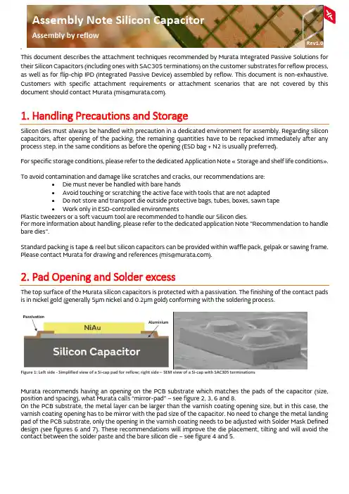
Assembly Note Silicon CapacitorAssembly by reflowRev1.0 This document describes the attachment techniques recommended by Murata Integrated Passive Solutions for their Silicon Capacitors (including ones with SAC305 terminations) on the customer substrates for reflow process, as well as for flip-chip IPD (Integrated Passive Device) assembled by reflow. This document is non-exhaustive. Customers with specific attachment requirements or attachment scenarios that are not covered by this documentshouldcontactMurata(**************).1. Handling Precautions and StorageSilicon dies must always be handled with precaution in a dedicated environment for assembly. Regarding silicon capacitors, after opening of the packing, the remaining quantities have to be repacked immediately after any process step, in the same conditions as before the opening (ESD bag + N2 is usually preferred).For specific storage conditions, please refer to the dedicated Application Note « Storage and shelf life conditions». To avoid contamination and damage like scratches and cracks, our recommendations are:•Die must never be handled with bare hands•Avoid touching or scratching the active face with tools that are not adapted•Do not store and transport die outside protective bags, tubes, boxes, sawn tape•Work only in ESD-controlled environmentsPlastic tweezers or a soft vacuum tool are recommended to handle our Silicon dies.For more information about handling, please refer to the dedicated application Note "Recommendation to handle bare dies".Standard packing is tape & reel but silicon capacitors can be provided within waffle pack, gelpak or sawing frame. PleasecontactMuratafordrawingandreferences(**************).2. Pad Opening and Solder excessThe top surface of the Murata silicon capacitors is protected with a passivation. The finishing of the contact pads is in nickel gold (generally 5µm nickel and 0.2µm gold) conforming with the soldering process.Figure 1: Left side - Simplified view of a Si-cap pad for reflow; right side – SEM view of a Si-cap with SAC305 terminationsMurata recommends having an opening on the PCB substrate which matches the pads of the capacitor (size, position and spacing), what Murata calls “mirror-pad” – see figure 2, 3, 6 and 8.On the PCB substrate, the metal layer can be larger than the varnish coating opening size, but in this case, the varnish coating opening has to be mirror with the pad size of the capacitor. No need to change the metal landing pad of the PCB substrate, only the opening in the varnish coating needs to be adjusted with Solder Mask Defined design (see figures 6 and 7). These recommendations will improve the die placement, tilting and will avoid the contact between the solder paste and the bare silicon die – see figure 4 and 5.2.1. Solder joint after reflowFigure 2: SMD AssemblyFigure 3: NSMD AssemblySilicon capacitor solder process is specific. Solder paste must not be in contact with the side of the silicon capacitor. Side of silicon capacitor must not be in contact with the landing pad. Correct assembly can be checked with the leakage current level of the capacitor after assembly. Please also check Figure 17 for mechanical measurement procedure of the solder joint after reflow.Tilt acceptance criteria is defined by customer and target application. Please contact Murata for more information.Figure 4 : Example of mis-assembly dueto solder paste excessFigure 5 : Si-cap tilting examples, please note thesolder excess2.2. Solder Mask designOn the customer substrate, Murata recommends SMD (Solder Mask Defined) to control the solder flowing on the tracks. Customer must ensure the opening and placement tolerances of the solder mask remain compatible with the silicon capacitor pad dimensions.Please take good note of the difference between Si-caps with NiAu finishing, that need solder paste on the PCB substrate (left side of figures 6 and 8) and Si-caps with SAC305 terminations (or SAC305 bump) that require no solder paste, but only flux (right side of figures 6 and 8). Solder paste and flux deposition methods are described on Section 4.2.2.1. Solder Mask DefinedFigure 6: Simplified view of SMD assembly from the side (only one pad is shown here)Figure 7: Examples of SMD designs, 2 pads on the left, 4 pads on the right2.2.2. Non Solder Mask DefinedFigure 8: Simplified view of NSMD assembly from the side (only one pad is shown here)Figure 9: Example of NSMD designs with 2 pads.Note : Varnish between the two landing pads can also be applied2.3. Pad openingLanding pads for the substrate and die pad dimensions for the Murata silicon die:Note: For RF and broadband design, please refer to application note “Design guidelines for transmission lines of UBB SiCap”0402M1000 x 50090250700Table 2: Landing pads for capacitors with four padsNote: For RF and broadband design, please refer to application note “Design guidelines for transmission lines of UBB SiCap”For components with a different number of pads, similar rules can be considered as a base. Please contact Murata for additional support.3. Pick and PlaceThe most common approach is with automatic equipment using vision assist to correct placement after picking but manual placement can also be done.Using a soft tip tool (like rubber) is particularly preferred for the die manipulation.For more details on tip tool selection please look at the dedicated Application Note “Recommendation to handle bare dies”.Please adjust the pressure force during placement to the capacitor size and solder amount below the component.0201M 600 x 300 100 150 200 0201 800 x 600 150 400 300 0402 1200 x 700 300 500 400 0402M 1000 x 500 260 300 280 0204M 500 x 1000 75 800 200 0603 1800 x 1100 400 900 800 0404M 1040 x 1040 300 850 240 0805 2200 x 1400 500 1200 1000 1206 3400 x 1800 600 1600 2000 18124700 x 360090034002700Table 1: Landing pads for capacitors with two pads4. Mounting Process Flow4.1. Silicon Capacitors with SAC305 terminationsThe bumps need flux to activate the soldering reflow. The following processes are compatible: 4.1.1. Flux dippingFigure 10: Assembly process by flux dipping on bumped capacitor with SAC305 terminations 4.1.2. Fluxing by stampingFigure 11: Assembly process by flux stamping on bumped capacitor with SAC305 terminations4.1.3. Fluxing by sprayingFigure 12: Assembly process by flux spraying on bumped capacitors with SAC305 terminations 4.1.4. Fluxing by screen printingFigure 13: Assembly process by screen printing of flux on bumped capacitors with SAC305 terminations4.2. Silicon Capacitors with NiAu finishingWe recommend placing the solder paste by screen printing directly on the substrate landing pads:Figure 14: Assembly process by screen printing of solder paste on silicon capacitor5. Solder print material and stencil printing recommendations 5.1. Silicon Capacitors with NiAu finishingSAC305 is commonly used and recommended but other materials compatible with the die pad finishing are also possible. Please contact Murata.Murata recommends using a type 6 powder size. Type 5 can be used depending on the customer PCB design and application. Type 4 is not recommended for 0201M and smaller pad dimensions. Depending on the die pad size, powder size can be adjusted. However, type 6 compared with type 4 limits the risk of tilting of the capacitor for smaller pad dimensions (refer to part 2).Alloy Composition Solidus Liquidus CommentsSAC305 Sn 96.5%, Ag 3%,Cu 0.5% 217°c 217°c EutecticSn63 Sn 63%, Pb 37% 183°c 183°c EutecticOnly for allowed applications AuSn Au 80%, Sn 20% 280°c 280°c Eutectic - High temperatureSnPb Sn 5%, Pb 95% 308°c 312°c High temperatureOnly for allowed applicationsTable 3 : Examples of solder print materials for reflowWater soluble and no clean flux can be used. In case of water-soluble flux, remove the flux immediately after reflow to avoid a potential issue of current leakage between pads.5.2. Stencil design rules in function of its gradeMurata advises in every case that the width of the stencil opening (referred as ‘W’) should be larger than 5 times the average powder size of your soldering material. This, in order to correctly fill the stencil pocket.Murata follows the IPC-7525 standard and quantifies the stencil grade based on ratio between stencil’s area ratio (AR), aspect ratio (AS) and thickness. Please look at the following formulas and tables to find the stencil grade we recommend.Figure 15: Definitions for stencil aperturePlease compare your stencil's desired thickness, aspect and area ratio with the following tables to define which grade we advise. Please consider the highest grade you will find from each of the three criteria.Table 4: Stencil grade selection criteria per Area ratio, Aspect ratio and ThicknessExamples of medium-high grade stencils include electroformed or laser-cut technologies.Examples of high grade stencils include plasma or medium-high grade with surface treatment technologies. For SAC305, a solder joint thickness of 40 µm +/-10 is targeted to limit the risk of contact between the solder paste and the side of the capacitor. Limiting solder joint thickness will also avoid an excessive tilting of the capacitor, especially for small components. Please contact Murata for other soldering materials and thinner solder joints.For example, below are some stencil designs advised by Murata (SAC305 type 6 with 50% of flux by volume):Stencil opening size (in µm) Stencil thickness (in µm)Stencil grade(roughness andopening profile)0201M 200 x 130 50 high0201 320 x 150 100 medium high0402M 260 x 240 100 medium high 0402 369 x 260 125 regular 0204M 750 x 90 75 medium high 0603 768 x 300 125 regular 0404M 250 x 750 125 regular 0805 400 x 960 125 regular 1206 500 x 1229 125 regular 1812650 x 3012125regularTable 5: Advised stencil designs per type for capacitors with two padsArea ratio (AR)Asepct ratio (AS)Thickness1.51.2 1.0110µm75µm0.660.50.4Note: Opening sizes are to be adjusted according to flux content and type used.Note: Opening sizes are to be adjusted according to flux content and type used.For components with a different amount of pads, similar rules can be considered as a base. Please contact Murata for additional support.6. Reflow by soldering6.1. Reflow recommendations at regular temperaturesMurata recommends convection reflow but vapor phase reflow and infrared reflow could be also used.The reflow process must be carried out in accordance with the JEDEC J-STD-020-E standard for low temperature reflow like SAC305. For higher temperature solder pastes, like AuSn, please refer to the dedicated Application Note “Silicon Capacitors assembly by reflow with high temperature soldering material”.Figure 16: General reflow profile for regular temperature solder pastes (based on J-STD-020-E)0402M120 x 12040highTable 6: Advised stencil designs per type for capacitors with four padsPreheat/soakTemperature min (Ts min) 150°C 100°CTemperature max (Ts max) 200°C 150°CTime (ts) from (Ts min to Ts max) 60 to 120 s 60 to 120 sRamp-upRamp-up rate (TL to Tp) 3°C/s maximum 3°C/s maximumLiquidus temperature(TL) 217°C 183°CTime (t) maintained above TL 60s to 150 s 60s to 150 sTime (tp) within 5°C of the maximumtemperature 30 seconds max 20 seconds maxPeak package body temperature (Tp) 260°C max 235°C maxTime 25°C to peak temperature 8 minutes maximum 6 minutes maximumRamp-downRamp-down rate (Tp to TL) 6°C/s maximum 6°C/s maximumTable 7 : Recommended values for regular temperature reflowAccording to JEDEC J-STD-020E, the user’s peak temperature must not exceed Tp and the time tp has to be respected. Values included in the above table may vary with the soldering material.Flux removes tarnish films, maintains surface cleanliness and facilitates solder spread during attachment operations. The flux must be compatible with the soldering temperature and soldering times. In case of water-soluble flux, please refer to the solder paste supplier for the cleaning and flux removal. Flux residues could be responsible for current leakage or short circuits. For optimum results, clean the circuits immediately after reflow.6.2. Procedure for solder joint measurement (after reflow)Figure 17: Solder joint measurement protocolAs step 1, the zero level reference is made at PCB surface.As step 2, the gauge shows ‘Y’ as the thickness of the whole assembly.X represents the thickness of the silicon capacitor, including the silicon capacitor pad.One should subtract X as well as the PCB landing pad’s thickness from Y to get the measured solder joint.MMMMMMMMMMMMMMMM MMssss MM MMMM jj ss jj jj jj jjℎjj ii iijjMMMMMM=YY−XX−ss MM jjMMjj jj ll ppMMMM jjℎjj ii iijjMMMMMMRevision history1.0 22/03/2021 Document Creation C.MullerDisclaimer / Life support applicationsThese products are not designed for use in life support appliances, devices, or systems where malfunction of these products can reasonably be expected to result in personal injury. Murata customers using or selling these products for use in such applications do so at their own risk and agree to fully indemnify Murata for any damages resulting from such improper use or sale.Reproduction in whole or in part is prohibited without the prior written consent of the copyright owner. The information presented in this document does not form part of any quotation or contract, is believed to be accurate and reliable and may be changed without notice. No liability will be accepted by the publisher for any consequence of its use. Publication thereof does not convey nor imply any license under patent or other industrial or intellectual property rights.**************Assembly Note Silicon Capacitor Assembly by reflow 14。
美国电子公司Murata电容器数据手册说明书
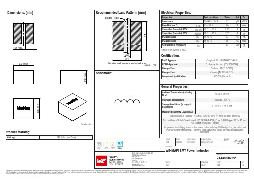
Dimensions: [mm]Scale - 8:1Product Marking:Marking2R2 (Inductance Code)744383360227443833602274438336022B C(mm)B(mm) min.178,001,507443833602274438336022T e m p e r a t u r eT pT L74438336022Cautions and Warnings:The following conditions apply to all goods within the product series of WE-MAPI ofWürth Elektronik eiSos GmbH & Co. KG:General:•This electronic component was designed and manufactured for use in general electronic equipment.•Würth Elektronik must be asked for written approval (following the PPAP procedure) before incorporating the components into any equipment in fields such as military, aerospace, aviation, nuclear control, submarine, transportation (automotive control, train control, ship control), transportation signal, disaster prevention, medical, public information network, etc. where higher safety and reliability are especially required and/or if there is the possibility of direct damage or human injury.•Electronic components that will be used in safety-critical or high-reliability applications, should be pre-evaluated by the customer. •The component is designed and manufactured to be used within the datasheet specified values. If the usage and operation conditions specified in the datasheet are not met, the wire insulation may be damaged or dissolved.•Do not drop or impact the components, the component may be damaged.•Würth Elektronik products are qualified according to international standards, which are listed in each product reliability report. Würth Elektronik does not guarantee any customer qualified product characteristics beyond Würth Elektroniks’ specifications, for its validity and sustainability over time.•The customer is responsible for the functionality of their own products. All technical specifications for standard products also apply to customer specific products.Product specific:Soldering:•The solder profile must comply with the technical product specifications. All other profiles will void the warranty.•All other soldering methods are at the customers’ own risk.•To improve the solderability of bottom termination components please refer to appnote ANP036 on our homepage.•Make sure that you use the correct thickness of solder paste to avoid an insufficient soldering result. We recommend 100µm solder paste as a reference.Cleaning and Washing:•Washing agents used during the production to clean the customer application may damage or change the characteristics of the wire insulation, marking or plating. Washing agents may have a negative effect on the long-term functionality of the product. Potting:•If the product is potted in the costumer application, the potting material may shrink or expand during and after hardening. Shrinking could lead to an incomplete seal, allowing contaminants into the core. Expansion could damage the components. We recommend a manual inspection after potting to avoid these effects.Storage Conditions:• A storage of Würth Electronik products for longer than 12 months is not recommended. Within other effects, the terminals may suffer degradation, resulting in bad solderability. Therefore, all products shall be used within the period of 12 months based on the day of shipment.•Do not expose the components to direct sunlight.•The storage conditions in the original packaging are defined according to DIN EN 61760-2.•The storage conditions stated in the original packaging apply to the storage time and not to the transportation time of the components. Packaging:•The packaging specifications apply only to purchase orders comprising whole packaging units. If the ordered quantity exceeds or is lower than the specified packaging unit, packaging in accordance with the packaging specifications cannot be ensured. Handling:•Violation of the technical product specifications such as exceeding the nominal rated current will void the warranty.•Applying currents with audio-frequency signals may result in audible noise due to the magnetostrictive material properties.•The temperature rise of the component must be taken into consideration. The operating temperature is comprised of ambient temperature and temperature rise of the component.The operating temperature of the component shall not exceed the maximum temperature specified.These cautions and warnings comply with the state of the scientific and technical knowledge and are believed to be accurate and reliable.However, no responsibility is assumed for inaccuracies or incompleteness.Würth Elektronik eiSos GmbH & Co. KGEMC & Inductive SolutionsMax-Eyth-Str. 174638 WaldenburgGermanyCHECKED REVISION DATE (YYYY-MM-DD)GENERAL TOLERANCE PROJECTIONMETHODEsAg003.0002023-03-31DIN ISO 2768-1mDESCRIPTIONWE-MAPI SMT Power InductorORDER CODE74438336022SIZE/TYPE BUSINESS UNIT STATUS PAGEImportant NotesThe following conditions apply to all goods within the product range of Würth Elektronik eiSos GmbH & Co. KG:1. General Customer ResponsibilitySome goods within the product range of Würth Elektronik eiSos GmbH & Co. KG contain statements regarding general suitability for certain application areas. These statements about suitability are based on our knowledge and experience of typical requirements concerning the areas, serve as general guidance and cannot be estimated as binding statements about the suitability for a customer application. The responsibility for the applicability and use in a particular customer design is always solely within the authority of the customer. Due to this fact it is up to the customer to evaluate, where appropriate to investigate and decide whether the device with the specific product characteristics described in the product specification is valid and suitable for the respective customer application or not.2. Customer Responsibility related to Specific, in particular Safety-Relevant ApplicationsIt has to be clearly pointed out that the possibility of a malfunction of electronic components or failure before the end of the usual lifetime cannot be completely eliminated in the current state of the art, even if the products are operated within the range of the specifications.In certain customer applications requiring a very high level of safety and especially in customer applications in which the malfunction or failure of an electronic component could endanger human life or health it must be ensured by most advanced technological aid of suitable design of the customer application that no injury or damage is caused to third parties in the event of malfunction or failure of an electronic component. Therefore, customer is cautioned to verify that data sheets are current before placing orders. The current data sheets can be downloaded at .3. Best Care and AttentionAny product-specific notes, cautions and warnings must be strictly observed. Any disregard will result in the loss of warranty.4. Customer Support for Product SpecificationsSome products within the product range may contain substances which are subject to restrictions in certain jurisdictions in order to serve specific technical requirements. Necessary information is available on request. In this case the field sales engineer or the internal sales person in charge should be contacted who will be happy to support in this matter.5. Product R&DDue to constant product improvement product specifications may change from time to time. As a standard reporting procedure of the Product Change Notification (PCN) according to the JEDEC-Standard inform about minor and major changes. In case of further queries regarding the PCN, the field sales engineer or the internal sales person in charge should be contacted. The basic responsibility of the customer as per Section 1 and 2 remains unaffected.6. Product Life CycleDue to technical progress and economical evaluation we also reserve the right to discontinue production and delivery of products. As a standard reporting procedure of the Product Termination Notification (PTN) according to the JEDEC-Standard we will inform at an early stage about inevitable product discontinuance. According to this we cannot guarantee that all products within our product range will always be available. Therefore it needs to be verified with the field sales engineer or the internal sales person in charge about the current product availability expectancy before or when the product for application design-in disposal is considered. The approach named above does not apply in the case of individual agreements deviating from the foregoing for customer-specific products.7. Property RightsAll the rights for contractual products produced by Würth Elektronik eiSos GmbH & Co. KG on the basis of ideas, development contracts as well as models or templates that are subject to copyright, patent or commercial protection supplied to the customer will remain with Würth Elektronik eiSos GmbH & Co. KG. Würth Elektronik eiSos GmbH & Co. KG does not warrant or represent that any license, either expressed or implied, is granted under any patent right, copyright, mask work right, or other intellectual property right relating to any combination, application, or process in which Würth Elektronik eiSos GmbH & Co. KG components or services are used.8. General Terms and ConditionsUnless otherwise agreed in individual contracts, all orders are subject to the current version of the “General Terms and Conditions of Würth Elektronik eiSos Group”, last version available at .Würth Elektronik eiSos GmbH & Co. KGEMC & Inductive SolutionsMax-Eyth-Str. 174638 WaldenburgGermanyCHECKED REVISION DATE (YYYY-MM-DD)GENERAL TOLERANCE PROJECTIONMETHODEsAg003.0002023-03-31DIN ISO 2768-1mDESCRIPTIONWE-MAPI SMT Power InductorORDER CODE74438336022SIZE/TYPE BUSINESS UNIT STATUS PAGE。
sfc操作手册
通过个人计算机连接运行中的 CPU 模块进行在线操作(特别是程序变更、强制输出、运行状态的 变更)时,应在熟读手册、充分确认安全的基础上进行操作。 操作错误可能导致发生机械损坏事故。
A-1
A-1
修订记录
印刷日期
手册编号
2008 年 01 月 SH-080741CHN-A 初版印刷
修订记录
手册编号在封底的左下角。
3.4.1 SFC 图写入方法 .................................................................. 3 - 7 3.4.2 SFC 图删除方法 .................................................................. 3 - 19 3.4.3 步属性变更方法 .................................................................. 3 - 20 3.4.4 SFC 图的剪切/复制/粘贴 .......................................................... 3 - 21 3.4.5 SFC 图排序 ...................................................................... 3 - 24 3.4.6 SFC 图的再显示 .................................................................. 3 - 25 3.5 动作输出·转移条件创建 .............................................................. 3 - 26 3.6 注释创建方法 ........................................................................ 3 - 27 3.6.1 SFC 注释创建方法 ................................................................ 3 - 27 3.6.2 软元件注释创建方法 .............................................................. 3 - 29 3.7 块信息设置 .......................................................................... 3 - 30 3.8 块列表显示 .......................................................................... 3 - 31 3.9 SFC 相关参数设置 .................................................................... 3 - 32 3.9.1 可编程控制器参数的 SFC 设置 ...................................................... 3 - 32 3.9.2 块参数的设置 .................................................................... 3 - 33 3.9.3 SFC 程序设置 .................................................................... 3 - 34 3.10 变换操作 ........................................................................... 3 - 34
艾索莱特产品选择指南说明书
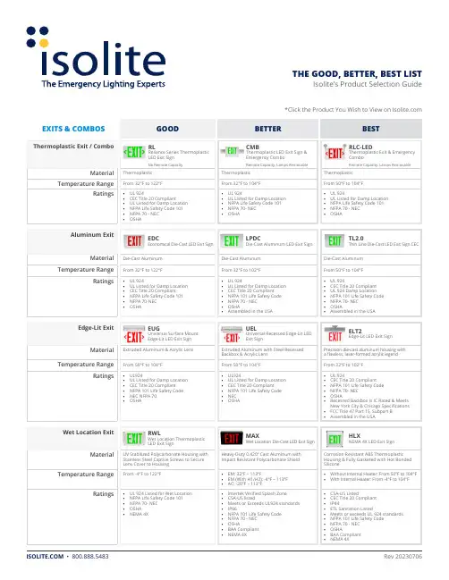
THE GOOD, BETTER, BEST LIST Isolite’s Product Selection Guide*Click the Product You Wish to View on EXITS & COMBOSRLReliance Series ThermoplasticLED Exit SignCMBThermoplastic LED Exit Sign &Emergency ComboRLC-LEDThermoplastic Exit & EmergencyComboNo Remote Capacity Remote Capacity, Lamps Removable Remote Capacity, Lamps Removable Thermoplastic Thermoplastic ThermoplasticFrom 32°F to 122°F From 32°F to 104°F From 50°F to 104°F• UL 924• CEC Title 20 Compliant• UL 924• UL Listed for Damp Location• UL 924• UL Listed for Damp LocationEDCEconomical Die-Cast LED Exit SignLPDCDie-Cast Aluminum LED Exit SignTL2.0Thin Line Die-Cast LED Exit Sign CEC Die-Cast Aluminum Die-Cast Aluminum Die-Cast AluminumFrom 32°F to 122°F From 32°F to 102°F From 50°F to 104°F• UL 924• UL Listed for Damp Location• UL 924• UL Listed for Damp Location• UL 924• CEC Title 20 CompliantEUGUniversal Surface MountEdge-Lit LED Exit SignUELUniversal Recessed Edge-Lit LEDExit SignELT2Edge-Lit LED Exit SignExtruded Aluminum & Acrylic Lens Extruded Aluminum with Steel RecessedBackbox & Acrylic LensPrecision die-cast aluminum housing witha flawless, laser-formed acrylic legendFrom 50°F to 104°F From 50°F to 104°F From 32°F to 102°F• UL924• UL Listed for Damp Location• UL924• UL Listed for Damp Location• UL 924• CEC Title 20 CompliantRWLWet Location ThermoplasticLED Exit SignMAXWet Location Die-Cast LED Exit SignHLXNEMA 4X LED Exit SignUV Stabilized Polycarbonate Housing withStainless Steel Captive Screws to SecureLens Cover to HousingHeavy-Duty 0.420” Cast Aluminum withImpact Resistant Polycarbonate ShieldCorrosion Resistant ABS ThermoplasticHousing & Fully Gasketed with Hot BondedSiliconeFrom -4°F to 122°F• EM: 32ºF – 113ºF• EM (With H1/H2): -4ºF – 113ºF• AC: -20ºF – 113ºF• Without Internal Heater: From 50°F to 104°F• With Internal Heater: From -4°F to 104°FTHE GOOD, BETTER, BEST LIST Isolite’s Product Selection Guide*Click the Product You Wish to View on EXITS & COMBOSCONTINUEDRWL-CWet Location Thermoplastic LEDExit SignMAX-CWet Location Die-Cast Exit &Emergency ComboHLX-CNEMA 4X Exit & Emergency ComboUV Resistant Polycarbonate Faceplate withHigh Impact Corrosion ResistantThermoplasticHeavy-Duty 0.420” Cast Aluminum LampHousing Constructed of VandalResistant PolycarbonateCorrosion Resistant, ABS Thermoplastic,Fully Gasketed with Hot Bonded SiliconeFrom 32°F to 122°F From 50°F to 104°F• Without Internal Heater: From 50°F to 104°F• With Internal Heater: From -4°F to 104°F• UL 924PHLThermoplastic PhotoluminescentExit SignPHAluminum Frame PhotoluminescentExit SignPH100Photoluminescent Exit SignThermoplastic Frame with Strontium OxideAluminate Photoluminescent PigmentMolded Into a Rigid Fire/Flame-ResistantPVC SheetExtruded Aluminum Frame With StrontiumOxide Aluminate Photoluminescent PigmentMolded Into a Rigid Flame/Fire-Resistant PVCSheetDurable ABS Background Panel Available inRed, Green, or Black, with PhotoluminescentLettersNon-Electrical Non-Electrical Non-ElectricalSLX-60ABS Plastic Frame Self-LuminousExit Sign2040-01Aluminum Frame Self-LuminousExit Sign880Thinline Aluminum Self-LuminousExit SignFlame Retardant, UV Stabilized, InjectionMolded ABS FrameExtruded Aluminum Frame with PaintedExtruded Aluminum StencilExtruded Aluminum Frame with PaintedExtruded Aluminum StencilFrom -67°F to 176°F From -67°F to 176°F From -67°F to 176°F• UL Listed to standard UL924 & CAN/• ULC-S572• UL Listed to standard UL924 & CAN/• ULC-S572• UL Listed to standard UL924 & CAN/• ULC-S572SLX-60 (VR)ABS Plastic Frame Self-LuminousExit Sign2040-95Vandal Resistant Self-LuminousExit Sign2040-70Vandal Proof Institutional Self-Luminous Exit SignFlame Retardant, UV Stabilized, InjectionMolded ABS Frame with VR ShieldExtruded Aluminum Frame Mounted inMolded ABS Protective Enclosure withPainted Aluminum StencilCast Aluminum Frame, 0.187” Thick,Extends from Faceplate At 45° Angle fromthe WallFrom -67°F to 176°F From -67°F to 176°F From -67°F to 176°F• UL Listed to standard UL924 & CAN/• UL Listed to standard UL924 & CAN/• UL Listed to standard UL924 & CAN/THE GOOD, BETTER, BEST LIST Isolite’s Product Selection Guide*Click the Product You Wish to View on EXITS & COMBOSCONTINUEDCLPChicago Approved LED Exit SignPGChicago Approved LED Edge-LitExit SignDurable 20-Gauge Steel Precision, Die-Cast Aluminum Housing withLaser Formed Acrylic LegendFrom 32°F to 122°F From 50°F to 104°F• City of Chicago Approved• CEC Title 20 Compliant• City of Chicago Approved• UL 924EDC-NYCNYC Approved EconomicalDie-Cast LED Exit SignELT2 with R8Edge-Lit LED Exit SignPremium-Grade, Aluminum Housing Precision Die-Cast Aluminum Housing with aFlawless, Laser-Formed Acrylic LegendFrom 32°F to 122°F From 32°F to 102°F• New York City Approved• UL Listed for Damp Location• UL 924• CEC Title 20 CompliantLP-CTMASteel Connecticut & MassachusettsCompliant LED Mobility Exit SignLPX-CTMAConnecticut & MassachusettsAluminum LED Mobility Exit SignECTMAConnecticut & MassachusettsCompliant Recessed Mobility Exit Sign Durable 20-Gauge Steel Durable, Extruded Aluminum Durable 20-Gauge Steel with White-BakedPowder Coat Finish & High Clarity AcrylicFrom 50°F to 113°F From 50°F to 113°F From 50°F to 113°F• CSA-US listed• Meets or exceeds UL 924 standards• CSA-US listed• UL 924• CSA-US listed• Meets or Exceeds UL 924 StandardsEU-CTMAConnecticut & MassachusettsCompliant Indoor Mobility Exit SignDurable 20-Gauge Steel with White-BakedPowder Coat Finish & High Clarity AcrylicFrom 50°F to 113°F• CSA-US listed• Meets or Exceeds UL 924 StandardsTHE GOOD, BETTER, BEST LIST Isolite’s Product Selection Guide*Click the Product You Wish to View on EXITS & COMBOSCONTINUEDHZEClass 1 Div 2 LED Exit SignHZCClass 1 Div 2 Exit & EmergencyComboEXPExplosion Proof Edge-Lit LEDExit SignDurable, Corrosion Resistant, GrayFiberglass & Fully Gasketed for Harsh &Hazardous Locations. High Clarity, ScratchResistant, Clear Polycarbonate FaceFully Gasketed, Die-Cast AluminumHousing with Impact ResistantPolycarbonate Lens Stainless Steel MountingFeet & Hardware Industrial Gray ColorStandardPrecision Die-Cast Aluminum Housing WithA Flawless, Laser-Formed Acrylic LegendFrom 50°F to 104°F From 50°F to 104°F From 50°F to 104°FLPDCCGDie-Cast Aluminum CustomGraphics SignTLCG2Thin Line Die-Cast Custom GraphicsLED Exit SignHeavy-Duty, Two Piece, Die-Cast AluminumAlloy Walls & Removable, Front Stencil Facewith Overlapping Light SealHeavy Duty, Two Piece Walls Constructed fromDie Cast Aluminum Alloy & Removable FrontStencil Face with Overlapping Light SealFrom 32°F to 102°F From 50°F to 104°F• UL 924• UL 924RL2LEDReliance Series Compact LEDEmergency LightEL16MR16 Emergency LightBUGHigh Performance LED EmergencyLightUV Stabilized, UL94V-O Flame Retardant,ABS Injection-Molded Thermoplastic5VA Flame Resistant, High-Impact Resistant,Thermoplastic in White or Black Finish5VA Flame Rated, Injection Molded AbsThermoplastic HousingFrom 50°F to 104°F From 68°F to 104°F From 50°F to 104°F125 Lumens per Lamp Lamp Option Dependent300-650 Lumens per LampTHE GOOD, BETTER, BEST LIST Isolite’s Product Selection Guide*Click the Product You Wish to View on EMERGENCY LIGHTINGCONTINUEDGNSDGenie MR16 Fully RecessedEmergency LightLMIGN2LED Compact Fully RecessedEmergency LightMIGN22nd Mini-Genie Fully RecessedCompact LED Emergency LightTextured White Powder, Coated Die-CastZinc Frame & DoorTextured, White Powder Coated, Die-CastZinc Frame & DoorTextured, White Powder Coated, Die-CastZinc Frame & DoorLamp Option Dependent561 Lumens407 Lumens per Lamp• LC: From 45°F to 85°F• NC: From 32°F to 102°FFrom 32°F to 102°F From 10°C to 40°CELS27-140 Watt Emergency LightELH120-360 Watt Emergency LightInjection Molded ABS Housing20-Gauge Steel Cabinet with Durable WhitePowder-Coat Finish20-Gauge Steel Cabinet with Durable WhitePowder-Coat Finish20-20-2With Internal Heater: 16°F to 104°F From 50°F to 113°F From 50°F to 113°FELL12-60 Watt Emergency Light20-Gauge Steel Cabinet with Durable WhitePowder-Coat Finish0-2From 50°F to 113°FTHE GOOD, BETTER, BEST LIST Isolite’s Product Selection Guide*Click the Product You Wish to View on EMERGENCY LIGHTINGCONTINUEDELEDArchitectural Outdoor LED LightOWLOutdoor Wet Location EmergencyLightDie-Cast Housing with Polycarbonate Lens &Mirror ReflectorQuality Pressure Die-Cast Aluminum HousingFinished in Durable Polyester Powder Coat1050 Lumens / 4000K CCT• AC Mode: 1530 Lumens• EM Mode: 600 Lumens• 3000K CCTHZLHazardous Location EmergencyLightFully Gasketed NEMA 4X Rated Fiberglass withHousing Durable Gray Powder-Coat FinishFully Gasketed, Die-Cast Aluminum HousingWith Impact Resistant Polycarbonate Lens0-20-2• Without Internal Heater: From 50°F to 104°F• With Internal Heater: From -4°F to 104°FFrom 50°F to 104°FRL2LED with LWReliance Series Compact LEDEmergency LightHZNNEMA 4X/IP66 Emergency LightHZZHazardous Location EmergencyLightUv Stabilized, UL94V-O Flame Retardant,ABS Injection-Molded ThermoplasticFully Gasketed, Die-Cast Aluminum Housingwith Impact Resistant Polycarbonate LensFully Gasketed, Die-Cast Aluminum Housingwith Impact Resistant Polycarbonate Lens125 Lumens per Lamp Lamp Option Dependent Lamp Option DependentFrom 50°F to 104°F• Without Internal Heater: From 50°F to 104°F• With Internal Heater: From -4°F to 104°FFrom 50°F to 104°F。
MURATA 聚合物铝电解电容器 说明书
C90C.pdf 10.12.28
电压 (VDC)
产品一览
Capacitance Value:电容值(µF)
6.8 8.2
10
15
22
33
47
56
68
82 100 150 180 220 270 330 470
2 4 6.3 10 12.5 16 D4
70
聚合物电容和 MLCC 解决方案
D4 D4
D4
静电容量 公差
%
20 20 20 20 20 20 20 20 20 20 20 20 20 20 20 20 20 20 20 20 20 20 20 20 20 20 20 20 20 20 20 20 20 20 20 20 20
代号
D4 D4 D4 D4 D6 D6 D4 D4 D4 D6 D6 D9 D4 D4 D4 D4 D4 D4 D6 D9 D4 D4 D4 D6 D9 D9 D4 D4 D4 D6 D6 D9 D9 D4 D4 D4 D6
16
9
9
D4 D4 20 16
D4 D6 D6 16 12 10
D4 D6 D6 67 6
D9 8
D4
D4 D4 D4
D4
D4 D6
D9
55
45
25
25
15
15
10
10
D4
D4 D4
55
28
25
D6
D9 D9
15
10
10
D4 D4 D4 D6 D6 D9
D9
55
45
30
25
20
20
12
D4 D4 D6 60 40 30
美国Millitech公司产品说明书:FXA LSA VPS精密和普通固定衰减器、水平设置衰减器和变
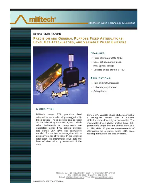
Millimeter-Wave Technology & SolutionsS ERIES FXA/LSA/VPSP RECISION AND G ENERAL P URPOSE F IXED A TTENUATORS,L EVEL S ET A TTENUATORS, AND V ARIABLE P HASE S HIFTERSF EATURES:•Fixed attenuators 0 to 40dB•Level set attenuators 25dB•Variable phase shifters 0-180°A PPLIC ATIONS:•Test and instrumentation•Laboratory equipment•SubsystemsD ESCRIPTIONMillitech series FXA precision fixedattenuators are made using a rugged split-block design. These devices can be usedas the laboratory standard against whichother instruments or components arecalibrated. Series FXA general purposeand series LSA level set attenuatorsconsist of a section of waveguide with aprecisely cut resistive vane. In the level setattenuator, the micrometer drive sets thelevel of attenuation by movement of thevane.Series VPS variable phase shifters consist ofa waveguide section with a movabledielectric vane driven by a micrometer. Themicrometer-driven phase shifters have 180°phase shift range and are offered from 26.5to 170 GHz. If precise measurements ofattenuation are required, series DRA directreading attenuators are also available.Millimeter-Wave Technology & Solutions (/(&75,&$/ 63(&,),&$7,216Model Number FXA-42 FXA-28 FXA-22 FXA-19 FXA-15 FXA-12 FXA-10 FXA-08 FXA-06 General Purpose Fixed AttenuatorsFrequency band and range (GHz)K18-26.5Ka26.5-40Q33-50U40-60V50-75E60-90W75-110F90-140D110-170Attenuation at center frequency range(dB)*13, 6, 10, 20, 30, 40VSWR (max) 1.15:1 1.15:1 1.15:1 1.15:1 1.15:1 1.15:1 1.15:1 1.20:1 1.5:1 Power rating (W) (max)*20.5 0.5 0.5 0.5 0.3 0.3 0.3 0.3 0.3 Precision Fixed AttenuatorsAttenuation across waveguide band --- 3, 6, 10, 20, 30, 40 --- --- Accuracy (±dB/%)*3 --- 0.7/4.0 0.7/4.0 0.7/4.0 0.7/4.0 0.7/4.0 0.7/4.0 --- --- Flatness (±dB) (max)*4 --- 0.7 0.7 0.7 0.7 0.7 0.7 --- --- VSWR (max) --- 1.05:1 1.05:1 1.06:1 1.08:1 1.08:1 1.08:1 --- --- Power rating (W) (max) --- 1.0 1.0 1.0 1.0 0.5 0.5 --- --- *1 – ±0.3 dB at center frequency. Please contact Millitech for attenuation values over full bandwidth.*2 – Higher power versions are available in all frequency bands. Please contact Millitech for details.*3 – Whichever is greater throughout the waveguide band.*4 – Flatness within the entire waveguide band.Model Number LSA-42 LSA-28 LSA-22 LSA-19 LSA-15 LSA-12 LSA-10 LSA-08 LSA-06 Level Set AttenuatorsFrequency band and range (GHz)K18-26.5Ka26.5-40Q33-50U40-60V50-75E60-90W75-110F90-140D110-170Attenuation (dB)*1 0-25 0-25 0-25 0-25 0-25 0-25 0-25 0-25 0-25 Insertion loss (dB) (max) 0.5 0.5 0.5 0.7 0.7 1.0 1.0 1.2 1.2 VSWR (max) 1.3:1 1.3:1 1.3:1 1.3:1 1.3:1 1.3:1 1.3:1 1.3:1 1.5:1 Power rating (W) (max)*20.5 0.5 0.5 0.3 0.3 0.3 0.3 0.3 0.3 Model Number VPS-42 VPS-28 VPS-22 VPS-19 VPS-15 VPS-12 VPS-10 VPS-08 VPS-06 Variable Phase ShiftersInsertion loss (dB) (max) --- 0.5 0.5 0.7 0.7 1.0 1.0 1.2 1.2 Phase shift range (degrees)*3 --- 0-180 0-180 0-180 0-180 0-180 0-180 0-180 0-180 VSWR (max) --- 1.3:1 1.3:1 1.3:1 1.3:1 1.3:1 1.3:1 1.3:1 1.5:1 Power rating (W) (max) --- 0.5 0.5 0.5 0.5 0.5 0.5 0.5 0.5*1 – Micrometer reading vs. attenuation value available upon request.*2 – Higher power versions are available in all frequency bands. Please contact Millitech for details.*3 – Measurements are made at the lowest frequency of the waveband guide.Millimeter-Wave Technology & SolutionsM ECHANICAL S PECIFICATIONSModel Number FXA-42 FXA-28 FXA-22 FXA-19 FXA-15 FXA-12 FXA-10 FXA-08 FXA-06 General Purpose Fixed Attenuators A (in/mm) 2.0/51 2.0/51 2.0/51 2.0/51 1.6/41 1.6/41 1.6/41 1.6/41 1.6/41 Precision Fixed Attenuators A (in/mm) *1 7.26/184 6.08/154 5.32/135 3.98/101 3.31/84 3.12/79 --- --- B (in/mm) *1 0.93/24 1.30/33 1.30/.33 0.86/22 0.86/22 0.86/22 --- --- C (in/mm) *1 1.33/34 1.33/34 1.33/34 1.20/30 1.20/30 1.20/30 --- --- Model Number LSA-42 LSA-28 LSA-22 LSA-19 LSA-15 LSA-12 LSA-10 LSA-08 LSA-06 Model Number VPS-42 VPS-28 VPS-22 VPS-19 VPS-15 VPS-12 VPS-10 VPS-08 VPS-06 Level Set Attenuators/Variable Phase Shifters A (in/mm)*13.45/883.40/86 3.40/86 3.25/83 3.25/83 3.25/83 3.17/81 3.17/81 Flange MIL.F-3922/54-001*2/54-003*2/67B-006/67B-007/67B-008/67B-009/67B-010/67B-M08/67B-M06*1 – Please contact Millitech for dimensions. *2 – With #4-40 threaded holes.H OW T O O RDERSpecify Model Number LSA-XX-AØØØØ VPS-XX-AØØØØFXA-XX-ABBCØXX = Waveguide Band WR – number A = Flange Type R – round (not available in WR-42) S – square (WR-42 and WR-28 only) P – pin contact (general purpose fixed attenuators WR-08 and WR-06 only) N – nonstandard (not available for precision fixed attenuators) BB = Attenuation Values* 03 – 3 dB 06 – 6 dB 10 – 10 dB 20 – 20 dB 30 – 30 dB40 – 40 dBC = Attenuator Type G – general purpose fixed version P – precision fixed version (WR-28 through WR-10 only)*Custom attenuation values available upon request for general purpose fixed attenuators.。
AMZTEL1电池产品规格书说明书
Revision/版本Content/目录SECTION/部分Page/页码1 Scope/适用范围: (5)2 Model Name/型号:278697 (5)3 Standard Environmental Test Conditions/标准环境测试条件: (5)4 Detailed Specifications/详细规格: (5)5 Warranty period/保质期: (6)6 Assembly Drawing (all unit is mm, not in scale) /电池图纸(单位:mm) (7)7 Terminal Specification/引脚定义 (11)8 PCM Specifications/保护板规格 (11)9Battery Packing requirement/电池包装要求: (14)10 Appendix Handling Precautions and Guidelines for LIP Rechargeable Batteries: (15)附录聚合物锂离子充电电池操作指示及注意事项 (15)11. Disclaimer/免责声明 (17)12. Miscellaneous/其他 (19)1 Scope/适用范围:The purpose of this Document (“Document”) is to specify the specifications of the Lithium-ion Polymer (“LIP”) rechargeable battery with ATL Part Number _GB-S02-278697-010H_(“Product” or “Pack”) to be supplied by ATL to Customer under Customer’s purchase order and ATL’s confirmation relevant to the Product. For the avoidance of doubt, the specifications specified herein do not apply to any Host Device, apparatus, instrument, equipment or hardware device containing Product or Cell (“Host Device”).本产品规格书描述了ATL依据客户采购订单生产的可充电聚合物锂离子(“LIP”)电池的产品性能指标,ATL产品代码号_GB-S02-278697-010H_(“产品” 或“电池”)。
保险丝管选型指南
保险丝管选型指南
选择分析: 1. 安全认证 满足产品最终的销售和使用的地域的地安规要求。 2. 产品应用电压 保险丝的电压额定值≥有效的电路电压。 3. 最大故障电流 保险丝管的分断能力≥电路中最大故障电流 4-5. 结构尺寸(长、宽、高) 设计电路中的空间限制,安装方式 总结:满足上述要求 、结合电路特点初步选择型号。 6. 保险丝最小额定电流=正常工作电/标准类别系数 IEC标准规格:Imin =正常工作电流/0.9 UL标准规格: Imin =正常工作电流/0.75
9
保险丝管选型指南
例2:选择250V 50T 保险丝管,正常工作电流1A、机箱内温度80℃,电 路开机一次脉冲电流如下图正弦波形,脉冲电流ia=20A,持续时间 ta= 6mS,要求开关机寿命10万次。
I2T值计算:(1/2)ia2ta = (1/2)*202*0.006 =1.2A2S
10
保险丝管选型指南
3
保险丝管选型指南
7. 安装位置周区环境温度 额定值百分比-环境温度
最小额定规格值In修正: Io min = In/额定值百分 比。
4
保险丝管选型指南
例1: 在某一使用场合,实际稳态正常工作电流是1.5A,选一 慢断型,其应选的保险丝最小额定电流Imin.: 在25℃场合: Io min =实际稳态电流/0.9=1.5/0.9=1. 7A(IEC标准) =正常工作电流/0.75=1.5/0.75=2.0A(UL标准) 在80℃场合:查图表知承载能力为额定值的78% Io min =正常工作电流1.5/0.9/78%= 2.14A(IEC标准) =正常工作电流1.5/0.75/78%=2.56A (UL标准)
好利来(中国)电子科技 股份有限公司
MC2000旋转机械保护系统
金属铝 280g
标准 RS232 串口(9 Way D-Type) Modbus RTU 自动 9600 bps 或 19200bps
上的模块都可以得到独立的电源供给和通讯服
务。
它既采用 DIN 导轨形式安装,也可以螺孔
安装,安装更便捷。基座包含 11 个槽位,其中
最左边 2 个槽位(1、2 槽位)固定用于安装 MC2020 电源模块,这是必须的。左边第 3 个
槽位固定用于安装 MC2030 网关通讯模块。其余 8 个槽位可以进行监测模块任意组合。
的组态文件进行读、写及修改操作。当在线使
用时,组态工具软件可以从模块向计算机上传组态信息,向模块下传组态信息及模块固件的
版本升级等,还可以浏览模块所采集的数据。
技术参数
参数名 操作系统 操作系统 计算机硬件
支持模块型号 MC2030 MC2101 MC2201 MC2301 MC2401 MC2501 功能 组态管理 固件升级 组态下载 组态上传 查看数据
标准串口(9 Way D-Type)、公口 标准串口(9 Way D-Type)、公口 RJ-45 接口 B 型、母口 11 个微型 D 连接器(36 Way D-Type)、母口 2 路电源端子、11 组信号端子
使用温度(-10 到+65℃)、存储温度(-20 到+75℃) ≤95%无冷凝 串口通讯电缆、DIN 导轨、导轨拉扣、固定螺栓、空白便签条
描述
压电式速度传感器、压电式加速度传感器、速度传感器、电涡流 传感器 位移、速度、加速度 1 路通道 1%FS 在软件中组态 >100KΩ 偏置电压测试 16 位 加速度(2-10KHz)、速度(2-10KHz)、位移(1-3KHz) 真有效值、峰-峰值、峰值 用户定义
施耐德低压开关柜产品样本和选型手册
在开关柜和开关的设计 和制造领域,施耐德电 气具有的关键技术使其 产品质量和技术优势得 到保证。
● 标准化元件的配置缩 短了交货和安装的时间
● 创新化设计、与其 它施耐德电气产品方案 的一致性可以给每个项 目再助一臂之力
● 施耐德电气的专家 与用户的亲密合作保证 对用户实地的安装要求 进行快速反应及有效的 服务
4
Blokset, 一致的、高性能的、经济的解 决方案
Blokset 的模块化设计可 以使安装成本合理化。
高质量高可靠性的产品 保证了供电的连续性和 系统的耐用性。
Blokset 是一种具有一 致性方案的产品: ● 对每项工程的技术 规范做出正确的响应 ● 安装简便,modular system ● standardised components ● fast manufacturing ● easy modifications
Functional design ● rationalised dimensions and layout inside the switchboard ● reduced footprint ● easy power and auxiliary connections ● easy installation upgrading at a controlled cost
● a modular structure for low-voltage switchboards, designed to meet local standards, practices and requirements.
● An intelligent system, ready to integrate devices containing advanced protection and communication functions for electrical distribution and motor control.