[]西门子FB125-DP通讯故障诊断
西门子DP网络诊断
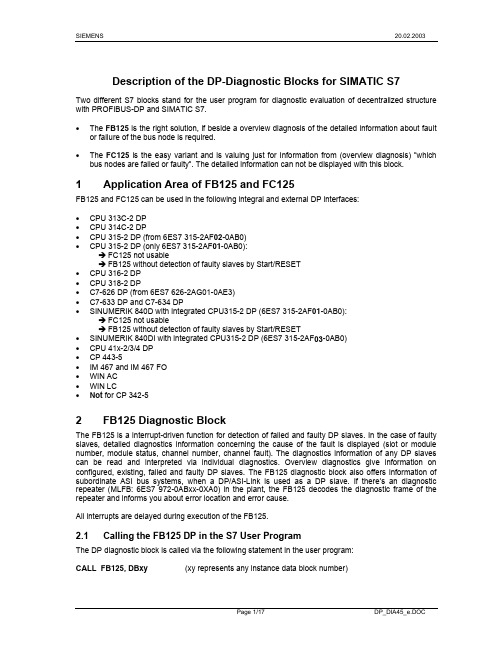
Description of the DP-Diagnostic Blocks for SIMATIC S7Two different S7 blocks stand for the user program for diagnostic evaluation of decentralized structure with PROFIBUS-DP and SIMATIC S7.• The FB125 is the right solution, if beside a overview diagnosis of the detailed information about fault or failure of the bus node is required.• The FC125 is the easy variant and is valuing just for Information from (overview diagnosis) ”which bus nodes are failed or faulty”. The detailed information can not be displayed with this block.1 Application Area of FB125 and FC125FB125 and FC125 can be used in the following integral and external DP interfaces:• CPU 313C-2 DP• CPU 314C-2 DP• CPU 315-2 DP (from 6ES7 315-2AF02-0AB0)• CPU 315-2 DP (only 6ES7 315-2AF01-0AB0):Î FC125 not usableÎ FB125 without detection of faulty slaves by Start/RESET• CPU 316-2 DP• CPU 318-2 DP• C7-626 DP (from 6ES7 626-2AG01-0AE3)• C7-633 DP and C7-634 DP• SINUMERIK 840D with integrated CPU315-2 DP (6ES7 315-2AF01-0AB0):Î FC125 not usableÎ FB125 without detection of faulty slaves by Start/RESET• SINUMERIK 840DI with integrated CPU315-2 DP (6ES7 315-2AF03-0AB0)• CPU 41x-2/3/4 DP• CP 443-5• IM 467 and IM 467 FO• WIN AC• WIN LC• Not for CP 342-5Block2 FB125DiagnosticThe FB125 is a interrupt-driven function for detection of failed and faulty DP slaves. In the case of faulty slaves, detailed diagnostics information concerning the cause of the fault is displayed (slot or module number, module status, channel number, channel fault). The diagnostics information of any DP slaves can be read and interpreted via individual diagnostics. Overview diagnostics give information on configured, existing, failed and faulty DP slaves. The FB125 diagnostic block also offers information of subordinate ASI bus systems, when a DP/ASI-Link is used as a DP slave. If there’s an diagnostic repeater (MLFB: 6ES7 972-0ABxx-0XA0) in the plant, the FB125 decodes the diagnostic frame of the repeater and informs you about error location and error cause.All interrupts are delayed during execution of the FB125.2.1 Calling the FB125 DP in the S7 User ProgramThe DP diagnostic block is called via the following statement in the user program:CALL FB125, DBxy(xy represents any instance data block number)The parameter list then appears automatically with the formal operands that are initialized with actual operands. Note: when calling the FB, it is not mandatory to initialize all parameters with an actual operand since the actual operands are stored in the instance data block.This call (including the same instance data block number and the same user actual operand) must be made in the three execution levels OB1, OB82 and OB86. A nested FB125 call in the three execution levels is possible (e.g.: OB82 → FC120 → FB125). The order and the contents of the 20 bytes of temporary local data of the organization blocks OB1, OB82 and OB86 must not be changed but can be extended at any time.The following system functions are used internally in the FB125: SFC13 and SFC51 with SZL 0C91 (in the case of an internal DP interface to the master CPU) or SZL 4C91 (in the case of an external DP interface to the CP/IM). It is not permissible to call SFC13 and/or SFC51 with SZL 0C91/4C91 in OB1 in addition to the FB125 call.Evaluation of the information at the block output parameters only makes sense in the cyclic program section (OB1).The block FB125 will be processed orderly, if the BIE-Bit is set as “1”. And The BIE-Bit will be removed, if the processing of FB125 was error.2.2 Parameters of the FB 125 and their meaningsInput parameters:• DP_MASTERSYSTEM (Int)Here, the number of the DP master system configured with STEP 7 must be specified.• EXTERNAL_DP_INTERFACE (Bool)Indicates whether the master DP interface is an integral interface (master CPU =0) or an external DP interface (CP/IM =1).• MANUAL_MODE (Bool)Manual mode: individual diagnosis of DP slaves is possible in this mode.• SINGLE_STEP_SLAVE (Bool)Transition to the next failed/faulty DP slave.• SINGLE_STEP_ERROR (Bool)Transition to the next error on the displayed DP slave.• RESET (Bool)Accept the specified number of DP master system and type of DP interface. Then the DP evaluation is initialized and restarted. The entire DP master system is regenerated, i.e. all configured, existing, failed and faulty DP slaves are automatically detected in an initialization routine.• SINGLE_DIAG (Bool)Manual mode: reading the individual diagnosis of a DP slave. The number of the slave is specified by the user at the “SINGLE_DIAG_ADR” parameter.• SINGLE_DIAG_ADR (Byte)Manual mode: the number of the slave for individual diagnosis.Output parameters:• ALL_DP_SLAVES_OK (Bool)Group indicator that the DP bus system is operating fault-free (1 ⇒ all slaves are o.k.)• SUM_SLAVES_DIAG (Byte)Number of affected DP slaves (failed or faulty). The number is detected for the first time at restart or warm restart.• SLAVE_ADR (Byte)Failed or faulty DP slave (range 1..126). In SINGLE_STEP_SLAVE mode, the next failed or faulty slave is indicated at each jog (dialing through of the affected slaves). The affected slaves are indicated in ascending order of slave addresses.• SLAVE_STATE (Byte)Information concerning the SLAVE_ADR: Status of the indicated slave.0: DP slave is o.k.1: DP slave failed2: DP slave faulty3: DP slave is not configured or DP slave cannot be diagnosed• SLAVE_IDENT_NO (Word)Information concerning the SLAVE_ADR: Profibus identification number of the indicated DP slave following PNO.• ERROR_NO (Byte)Information concerning the SLAVE_ADR:Current error number indicated for the affected slave. This allows all errors/faults to be distinguished from each other via a unique number.• ERROR_TYPE (Byte)Information concerning the SLAVE_ADR:1: Slot diagnosis (general specification of the faulty slot/module)2: Module status (refinement of slot diagnosis to include the status of the slot/module)3: Channel diagnosis (location of module no, channel no, channel error type in accordance with DP standard)4: S7 diagnosis (location of module no, channel no and channel error type)This applies only to S7 slaves or S7 modules from Siemens. The diagnostic information is taken from the S7 diagnostic data record DS0 or DS1.5: Unit diagnosis (the unit specification of diagnostic data define the slave product and it describe in the manual of slave). The slave diagnostic data is displayed in byte 932 to 1175 of instance data block.6: Cable diagnosis (error location and error cause detected from diagnostic repeater)• MODULE_NO (Byte)Information concerning the SLAVE_ADR: Number of the faulty module of the slave (slot no. or module no.).• MODULE_STATE (Byte)Information concerning the SLAVE_ADR: Status of the module (only in the case of module status as ERROR_TYPE):0: Module o.k., valid user data1: Module fault, invalid user data2: Incorrect module, invalid user data3: No module, invalid user data• CHANNEL_NO (Byte)Information concerning the SLAVE_ADR: Number of the faulty channel on the module.• CHANNEL_TYPE (Byte)Information concerning the SLAVE_ADR: Type of the faulty channel on the module.Type (Hex) Meaning00 Reserved01 Input02 Output03 Input-/Output04-1F Reserved20 PtP-Coupling21-2F Reserved30 F-DigitalInputOutput31 F-Digital32-3F Reserved40 DI SINAUT RTU41 CO SINAUT RTU42-4F Reserved50 SIWAREX51-54 Reserved55 DP-Interface module (Slave)56-5F Reserved60 Bit I/O (e.g. ASI-CP)61 HART-Input62 Reserved63 HART-Output64-6F Reserved70 Digital-Input71 Analog-Input72 Digital-Output73 Analog-Output74 FM-POS75 FM-REG76 FM-COUNT77 FM-TECHNO78 FM-NCU79 SM-POS-INPUT7A DESINA-Channel(Input)channel7B DP-Norm(Output)channel7C DP-Norm(other)7D DP-Normchannel7E Ultrasound position detection (USW 300)7F-FF Reserved• CHANNEL_ERROR_CODE (Int)Information concerning the SLAVE_ADR: Every channel error is assigned a clear error information.Code Meaning0 -1 Short-circuit (e.g. on the encoder line or on the output line)2 Undervoltage (supply voltage)3 Overvoltage (supply voltage)4 Overload5 Overtemperature6 Wire break (e.g. on the sensor)7 Upper limit violated8 Lower limit violated9 Fault (e.g. encoder supply, load voltage at the output, end of service life)10-15 -error16 Parameterization17 No encoder voltage or load voltagefuse18 Defective19 -fault20 Grounderrorchannel21 Reference22 Process interrupt lost23 Actuatorwarningshutdown24 ActuatorCode Meaning25 Safety-related shutdown 26 External fault (e.g. sensor fault, actuator fault) 27 Fault not clear 28-31 -32 ASI-Diagnosis 33 Configuring error/parameterization error 34 Ground fault 35 P short-circuit (encoder) 36 M short-circuit 37 Wire break 38 No encoder supply 39-48 - 65 Configuring error/parameterization error 66 Common-mode fault 67 P short-circuit (encoder) 68 M short-circuit 69 Wire break 70 Reference channel fault 71 Measuring range violation 72 Measuring range violation 73-96 - 97 Configuring error/parameterization error 98 Ground fault 99 P short-circuit (encoder 100 M short-circuit 101 Wire break 102 Fuse tripped 103 No load voltage 104 Overtemperature 105-128 - 129 Configuring error/parameterization error 130 Common-mode fault 131 P short-circuit 132 M short-circuit 133 Wire break 134 - 135 No external load voltage 136 - 137 Connection not wired 138 Open conductor to + 139 Open conductor to - 140 Calibration error 141 Range error (underrange or overrange) 142 - 143 Open conductor of the current source 144 User calibration does not correspond to parameterization 161 Encoder wire break 162 Absolute encoder fault 163 Error pulses incremental encoder or no zero mark 164 Voltage monitoring encoder 165 Voltage monitoring 15V 166 Voltage monitoring digital output 167 -168 Operating error 169 Error in machine data 170 Error set point 171 Error in cam data 172 Travel range monitoring 173 Operating range monitoring 174 Actual value monitoring 175 Target intakes monitoring 176 Target range monitoring 193 Analog input hardware fault 194 - 195 Analog input wire break (4-20mA only) 196 - 197 Analog input measuring range violation (underrange) 198 Analog input measuring range violation (overrange)Code Meaning 199 Analog output wire break200 Analog output short-circuit201-224 -225 Signal A error226 Signal B error227 Signal N errorvalue228 Falsely229 Fault 5.2V encoder supply230 Fault 24V encoder supply231 Encoder signal line short-circuit/wire break232 Parameter assignment error233-256 -257-288 -289-320 -321-352 -353-356 -error357 sensor/actuator358-384 -385 -386 Short-circuit (e.g. on the encoder line or on the output line)387 Undervoltage (supply voltage)388 Overvoltage (supply voltage)389 Overload390 Overtemperature391 Wire break (e.g. on the sensor)392 Upper limit violated393 Lower limit violated394 Fault (e.g. encoder supply, load voltage at the output, end of service life)395-400 -error401 Parameterization402 No encoder voltage or load voltagefuse403 Defective404 -fault405 Grounderrorchannel406 Reference407 Process interrupt lost408 Actuatorwarningshutdown409 Actuatorshutdown410 Safety-related411 External fault (e.g. sensor fault, actuator fault)412 Fault not clear413-416 -417 -418 Short-circuit (e.g. on the encoder line or on the output line)419 Undervoltage (supply voltage)420 Overvoltage (supply voltage)421 Overload422 Overtemperature423 Wire break (e.g. on the sensor)424 Upper limit violated425 Lower limit violated426 Fault (e.g. encoder supply, load voltage at the output, end of service life)427-432 -error433 Parameterization434 No encoder voltage or load voltagefuse435 Defective436 -437 Groundfaulterror438 Referencechannel439 Process interrupt lost440 Actuatorwarningshutdown441 Actuatorshutdown442 Safety-related443 External fault (e.g. sensor fault, actuator fault)444 Fault not clear445-448 -449 -450 Short-circuit (e.g. on the encoder line or on the output line)Code Meaning 451 Undervoltage (supply voltage)452 Overvoltage (supply voltage)453 Overload454 Overtemperature455 Wire break (e.g. on the sensor)456 Upper limit violated457 Lower limit violated458 Fault (e.g. encoder supply, load voltage at the output, end of service life)459-464 -error465 Parameterization466 No encoder voltage or load voltagefuse467 Defective468 -fault469 Grounderrorchannel470 Reference471 Process interrupt lost472 Actuatorwarningshutdown473 Actuatorshutdown474 Safety-related475 External fault (e.g. sensor fault, actuator fault)476 Fault not clear477-480 -481 Parameter assignment error482 -483 -484 -break485 Wireerror486 Pulse487 -overflow488 Counter489-516 -517 No external auxiliary voltageVoltage on ASI -Interface to low (APF)518 No front connectorparameterization519 Nomodule520 Incorrect parameters in the module521-528 -529 Incorrect user module or no user module, e.g. coding key position does not conform to the parameterAt least one ASI slave deviates from the set specification530 Communication fault on the module531 Operating state0: I-Slave in RUN / ASI-Link in operating state1: I-Slave in STOP / ASI-Link in offline state532 Internal watchdog tripped533 Module internal supply voltage failedempty534 Batteryfailedbackup535 Entire536 -537 Expansion unit failed538 Processorfailurefault539 EPROMfault540 RAM541 ADC/DACerror542 Fuse failure, all channel fuses have failed543 Process interrupt lost544 -545 Unit diagnosis: see DB125 Byte 932-1175 & manual546 Error cause and location not clear547 -548 -549 More than one measurements on DP2550 More than one measurements on DP3551 -552 Error cause not clear553 Message fault rate is critical554 Break in the signal line A555 Short circuit between signal line B to screenCode Meaning556 -557 Short circuit between signal line A to screen558 Break in the signal line B559 -560 Break line A and/or B or terminator is missing561 Break line A and/or B or an additional terminator is inserted562 Segment de-activated automatically, because line level=0563 Segment de-activated automatically, because line level=unsteady564 -565 -566 More than 32 nodes are connected to the measurement segment567 The distance of the node to the Diagnostic Repeater exceeds the permitted line length568 The maximum permitted number of Diagnostic Repeaters connected in series is exceeded569 The diagnostic Repeater has recognized further faults• CHANNEL_ERROR_INFO_1 (Dword)Information concerning the SLAVE_ADR: Bit-coded error information on the faulty channel. Different error information is assigned to the error types.Channel error information in accordance with the DP standard is assigned to the error type (3) channel diagnosis:Bit Channel Error Information in Accordance with DP Standard0 Reserved1 Short-circuit (e.g. on the encoder line or on the output line)2 Undervoltage (supply voltage)voltage)(supply3 Overvoltage4 Overload5 Overtemperature6 Wire break (e.g. on the sensor)7 Upper limit violated8 Lower limit violated9 Fault (e.g. encoder supply, load voltage at the output, end of service life)10-15 Reservederror16 Parameterization17 No encoder voltage or load voltagefuse18 Defective19 Reserved20 Groundfaultchannelerror21 Reference22 Process interrupt lostwarning23 Actuatorshutdown24 Actuatorshutdown25 Safety-related26 External fault (e.g. sensor fault, actuator fault)27 Fault not clear28-31 Reserved (initialized with 0)Channel error information containing the diagnostic data record DS1 of the S7 slaves or the S7 modules is assigned to the error type (4) S7 diagnosis:If an ASI network is connected to a DP slave (CHANNEL_TYPE =60hex e.g. DP/ASI-Link), the ASI address from 0 to 31 will get a value of …1“ in this bit stream.S7 signal modules (SMs):Bit Digital Input Module Digital Output Module0.0 Configuring error/parameterization error Configuring error/parameterization errorfaultfault Ground0.1 Ground0.2 P short-circuit (encoder) P short-circuit (encoder0.3 M short-circuit M short-circuitbreak0.4 Wirebreak Wire0.5 No encoder supply Fuse tripped0.6 Reserved No load voltage0.7 Reserved Overtemperature1.0-3.7 Reserved ReservedBit Analog Input Module Analog Output Module0.0 Configuring error/parameterization error Configuring error/parameterization errorfaultfault Common-mode0.1 Common-mode0.2 P short-circuit (encoder) P short-circuit0.3 M short-circuit M short-circuitbreakbreak Wire0.4 Wirefault Reserved0.5 Referencechannel0.6 Measuring range violation No external load voltageviolation Reservedrange0.7 Measuring1.0 Reserved Connection not wired1.1 Reserved Open conductor to +1.2 Reserved Open conductor to -error1.3 Reserved Calibration1.4 Reserved Range error (underrange or overrange)1.5 Reserved Reserved1.6 Reserved Open conductor of the current source1.7 Reserved User calibration does not correspond toparameterization2.0-3.7 Reserved ReservedS7 function modules (FMs):Bit FM 350 / FM 350-1 (FM COUNT)0.0 Signal A error0.1 Signal B error0.2 Signal N errorvalue0.3 Falsely0.4 Fault 5.2V encoder supply0.5 Fault 24V encoder supply0.6 Encoder signal line short-circuit/wire break0.7 Parameter assignment error1.0-3.7 ReservedBit FM 351 / 352 / 353 / 354 (FM POS)0.0 Encoder wire break0.1 Absolute encoder fault0.2 Error pulses incremental encoder or no zero mark0.3 Voltage monitoring encoder0.4 Voltage monitoring 15V0.5 Voltage monitoring digital output0.6 Reserved0.7 Operatingerror1.0 Error in machine datasetpoint1.1 Error1.2 Error in cam datarangemonitoring1.3 Travel1.4 Operating range monitoring1.5 Actual value monitoring1.6 Target intakes monitoring1.7 Target range monitoring2.0-3.7 ReservedBit FM 355 (FM REG)0.0 Analog input hardware fault0.1 Reserved0.2 Analog input wire break (4-20mA only)0.3 Reserved0.4 Analog input measuring range violation(underrange)0.5 Analog input measuring range violation (overrange)0.6 Analog output wire break0.7 Analog output short-circuit1.0-3.7 ReservedOther S7 modules:Bit DESINA0.0 Reserved0.1 Reserved0.2 Reserved0.3 Reservederror0.4 sensor/actuator0.5 Reserved0.6 Reserved0.7 Reserved1.0-3.7 ReservedBit Ultrasonic Way entry (USW 300)0.0 Parameter assignment error0.1 Reserved0.2 Reserved0.3 Reservedbreak0.4 Wireerror0.5 Pulse0.6 Reserved0.7 Counteroverflow1.0-3.7 ReservedBit Channel granular-Peripherie (e.g. ASI-CP)0.0 Module / ASI-Slave 0 faulty0.1 Module / ASI-Slave 10.2 Module / ASI-Slave 20.3 Module / ASI-Slave 30.4 Module / ASI-Slave 40.5 Module / ASI-Slave 50.6 Module / ASI-Slave 60.7 Module / ASI-Slave 71.0 Module / ASI-Slave 81.1 Module / ASI-Slave 9... ...3.6 Module / ASI-Slave 303.7 Module / ASI-Slave 31• CHANNEL_ERROR_INFO_2 (Dword)Information concerning SLAVE_ADR: In the case of the error type (4) S7 diagnosis, special error information that corresponds in content to the data record DS0 is additionally assigned to all S7 slaves or S7 modules.If an ASI network is connected to a DP slave (CHANNEL_TYPE =60hex e.g. DP/ASI-Link) with a maximum of 62 stations, the ASI address from 0 to 31 will get a value of …1“ in this bit stream.Bit S7 Diagnostic Data ASI-Slave0 S7 module fault 0bBit S7 Diagnostic Data ASI-Slave fault 1b1 Internalfault 2b2 External3bfault3 ChannelAt least one ASI slave deviates from the set specification4b4 No external auxiliary voltageVoltage on ASI -Interface to low (APF)5 No front connector 5b6 No module parameterization 6b7 Incorrect parameters in the module 7b8b-11b 8-11 Moduleclass:0000: Reserved0001: Reserved0010: S7 special module, e.g. adapter casing0011: DP standard slave0100: S7 interface module (IM)0101: S7 analog module0110: Reserved0111: Reserved1000: S7 function module (FM)1001: Reserved1010: Reserved1011: S7 interface modules to DP, e.g. I slave1100: S7 communications processor (CP)1101: Reserved1110: Reserved1111: S7 digital module12 Channel information exists 12b13 User information exists 13b14 Diagnostic interrupt from wildcard 14b15 Reserved 15b16b16 Incorrect user module or no user module, e.g. coding key position does not conform to theparameterAt least one ASI slave deviates from the set specification17 Communication fault on the module 17b18bstate18 Operating0: I-Slave in RUN / ASI-Link in normal state,1: I-Slave in STOP / ASI-Link in offline statetripped 19b19 Internalwatchdog20 Module internal supply voltage failed 20bempty 21b21 Battery22 Entire backup failed 22b23 Reserved 23b24 Expansion unit failed 24bfailure 25b25 Processorfault 26b26 EPROMfault 27b27 RAMerror 28b28 ADC/DAC29 Fuse failure, all channel fuses have failed 29b30 Process interrupt lost 30b31 Reserved 31b• DIAG_COUNTER (Byte)Info of SLAVE_ADR: Sum of all diagnostic of the displayed DP slaves.• DIAG_OVERFLOW (Bool)Number of simultaneously received diagnoses >32, i.e., slaves initiating more diagnoses than the FB125 can process. This can only arise when CPs or IMs are used as DP masters. It makes sense to execute a RESET here.• BUSY (Bool)This parameter indicates that the FB is currently evaluating the DP system. The information indicated can only be further processed after completion of the evaluation.2.3 Description of the Instance Data BlockThe instance data block is assigned to the diagnostic FB. The number of the data block is freely selectable in the FB call. The instance data block must on no account be modified by write accesses.The following data can be read from the instance data block by the user and evaluated:• Bytes 932 to 1175: Standard diagnostic data of the currently affected and indicated slave • Bytes 1176 to 1191: Configured slaves as bit register• Bytes 1192 to 1207: Existing (accessible) slaves as bit register • Bytes 1208 to 1223: Failed (inaccessible) slaves as bit register • Bytes 1224 to 1239: Faulty slaves as bit register• Bytes 1240 to 1255: Affected slaves (failed or faulty) as bit register• Bytes 1256 to 1271: Affected slaves stored as bit register, i.e. incoming slave diagnoses (faulty orfailed) are stored in this bit register until the bit register is deleted again via CPU complete restart or block RESET.• Bytes 1272 bis 1397: Number of diagnostics per slave (Slave1: Byte 1272 ... Slave126: Byte 1397)A bit is assigned to every DP bus node in all bit registers.DBB x+4DBB x+5DBB x+6DBB x+7DBB x+8DBB x+9DBB x+10DBB x+11DBB x+12DBB x+13DBB x+14DBB x+15DBB xDBB x+1DBB x+2DBB x+318Slave-Nr.9161724253240334148128DBD x495664577265807388819689104971121051201131212.4 FC125 Technical SpecificationsRuntime without pending diagnostic message: depend on the DP master e.g. CPU 315-2 DP as DP master: approx. 4msRuntime with pending diagnostic message: depend on the DP master and the slave diagnosislengthe.g. CPU 315-2 DP as DP master: approx. 11msMemory used in the CPU: 6,3 Kbytes2.5 Example FB125 callDuring the restart phase of the CPU (1st OB1 cycle) and at a RESET, the entire DP system is captured in FB125 via an initialization routine. Following this, diagnosis are interrupt-driven, i.e. when a diagnosis/station failure is received, evaluations are made in the relevant error OBs. This means no call condition need be generated for the block (see Fig. 1).Fig. 1: FB125 call example Note: It is not mandatory to initialize all block parameters with actual operands.CALL FB125, DB125 DP_MASTERSYSTEM :=1 EXTERNAL_DP_INTERFACE := FALSE MANUAL_MODE := E8.0 SINGLE_STEP_SLAVE := E8.1 SINGLE_STEP_ERROR :=E8.2 RESET := E8.3 SINGLE_DIAG :=E8.4 SINGLE_DIAG_ADR := MB125 ALL_DP_SLAVES_OK := M100.0 SUM_SLAVES_DIAG :=MB102SLAVE_ADR := MB103 SLAVE_STATE := MB104 SLAVE_IDENT_NO :=MW106 ERROR_NO :=MB108 ERROR_TYPE := MB109 MODULE_NO :=MB110 MODULE_STATE := MB111 CHANNEL_NO := MB112 CHANNEL_TYPE := MB113CHANNEL_ERROR_CODE :=MW114 CHANNEL_ERROR_INFO_1 := MD116CHANNEL_ERROR_INFO_2 :=MD120 DIAG_COUNTER := MB124DIAG_OVERFLOW := M100.1 BUSY := M100.2OB1 / OB82 / OB862.6 Use of the FB125The total number of affected slaves (failed or faulty) can be seen from the output parameter “SUM_SLAVES_DIAG”. If no slaves are affected, the bit “ALL_DP_SLAVES_OK” is set as group information.The bit register “existed, failed, faulty and affected slaves” will be updated basically in every operating methods.2.6.1 Automatic operation (MANUAL_MODE=0)• “SINGLE_STEP_SLAVE” jogs from one affected slave to the next. When the slave is indicated, you can jog through the errors on this slave and have them indicated as “SINGLE_STEP_ERROR”. The errors are distinguished by an error number that is incremented when jogging through the errors. If a new error jog is executed while the error with the highest number is indicated, error no. 1 appears again.• If you jog to the next affected slave, error evaluation of the new indicated slave is restarted. The first error of the slave is displayed automatically.• If a new diagnosis (e.g. one of 3 pending errors disappears) arrives from an affected slave while its error information is displayed, the error evaluation of the slave starts a new. In this case the first error is displayed.• All detected errors are displayed. This means that redundant information already located in the diagnostic frame of the slave can also be displayed at the output parameters of FB125 (but with different information content). The user must decide on the error types that are of interest to him. He can distinguish between the error types and assign them via the output parameter “ERROR_TYPE”. • An error code (1..569) is affected to each channel error and is displayed viaCHANNEL_ERROR_CODE”.• All diagnostics of the concerned slaves are displayed in …DIAG_COUNTER“. All station errors are counted (appearing and disappearing errors).2.6.2 Manual operation (MANUAL_MODE=1)• In manual operation (MANUAL_MODE), individual diagnosis of a slave can be carried out by specifying a DP slave number at the parameter “SINGLE_DIAG_ADR”. Jogging the errors on this slave is then also possible via “SINGLE_STEP_ERROR” (like in automatics mode).• Individual diagnosis represent a snapshot of the diagnosis of the specified slave that will be removed via parameter “SINGLE_DIAG”. If the individual diagnosis is repeated, the diagnostic frame of the slave is read again and the evaluation is restarted.。
dp通讯故障快速处理方法

dp通讯故障快速处理方法
1.初步检查:首先检查网络线路是否接触良好,是否有过长的线路导致信号衰减。
同时,查看网络负载是否过大,因为过大的负载也可能导致通讯不稳定。
2.硬件检查:检查所有硬件的基本接线及通信原理,确保PLC、触摸屏、ET200等主要硬件设备工作正常。
特别注意检查M12通信及电源接头是否接触良好。
3.使用DP网络寻找故障点:采用逐一加站原则,先甩开所有从站,从DP网路离CPU最近的第一个DP站开始诊断。
如果全线只有某一个站报警,直接判断该站为通讯故障位置。
如果全线只有末站或末段报警,在故障段继续采用逐一加站原则进行诊断。
如果全线报警,则直接采用逐一加站原则进行诊断。
4.软件诊断:使用相关的诊断软件(如ProfiTrace)对网络进行诊断,查看网络拓扑结构,以便更好地定位故障点。
5.增加抗干扰设备:对于干扰严重的区域,可以尝试增加抗干扰设备,以提高通讯的稳定性。
6.替换法:如果通过以上方法仍无法确定故障点,可以尝试使用替换法,逐一替换可能存在问题的硬件设备,以便快速找到故障点。
西门子PLC故障诊断简易教程

程序检查法
总结词
检查PLC的程序是否存在错误或异常 ,以确定故障原因。
详细描述
通过查看PLC的程序,检查程序逻辑 是否正确,是否存在死循环、错误指 令等问题;同时检查程序中是否有异 常的输入或输出。
模拟信号检查法
总结词
模拟输入信号,观察PLC的输出是否正常,以确定输入输出模块是否存在故障。
详细描述
BIG DATA EMPOWERS TO CREATE A NEW ERA
西门子PLC故障诊断简易教 程
汇报人:可编辑 2024-01-11
• PLC故障诊断基础 • 西门子PLC常见故障 • 西门子PLC故障诊断方法 • 西门子PLC故障诊断实例
目录
CONTENTS
01
PLC故障诊断基础
BIG DATA EMPOWERS TO CREATE A NEW
检查电源和通讯
检查PLC的电源和通讯是否正常 ,这是最基本的故障排查步骤 。
诊断软件和硬件
通过诊断软件检查PLC的软件系 统和硬件状态,确定故障的具 体位置。
修复或更换故障部件
根据故障的具体情况,修复或 更换故障部件,恢复PLC的正常
运行。
PLC故障诊断工具
诊断软件
示波器
西门子提供的诊断软件,可以检测PLC的硬 件和软件状态,帮助用户快速定位故障。
详细描述
通信故障可能由网络通信线缆损坏、通信端口设置不正确、通信协议不匹配等 因素引起。诊断时,应检查通信线缆是否完好,通信端口设置是否正确,以及 通信协议是否匹配。
输入/输出故障
总结词
输入/输出故障可能导致PLC无法接收外部信号或无法正确输出控制信号。
详细描述
输入/输出故障可能由输入/输出模块损坏、信号线连接不良、外部设备故障等因 素引起。诊断时,应检查输入/输出模块是否正常工作,信号线连接是否牢固, 以及外部设备是否正常工作。
解读西门子DP通信总线故障原因及处理方式
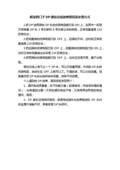
解读西门子DP通信总线故障原因及处理方式
1.把DP线两端的DP头的终端电阻都打到ON上,在其中一段用万用表量DP头3号引脚和8号引脚之间的电阻,正常测量值是110欧姆左右;
2.把测量端的终端电阻打到OFF上,远端的不动,这时的正常测量值是220欧姆左右;
3.把远端的终端电阻打到OFF上,测量端的终端电阻打到ON上,这时正常的测量值也应该是220欧姆左右;
4.把两端的终端电阻都打到OFF上,这时应该是开路,量不出电阻。
假如总线上有不止一个DP头,可以只测量两端,中间的DP头的终端电阻,始终处在OFF上就可以了。
不通的话,可以分段测量。
但是最好把DP头的出线拆掉来测量,排除干扰因素。
个人遇到的DP故障,原因目前发现两个:
1、通讯电缆质量差,抗干扰能力差(前提接地,布线很合理的情况),也有遇到过第一次买的通讯电缆不够,又使用其他种类的电缆情况,混用;
2、DP接头没有做好接地,就是电缆接头处的屏蔽线和DP头内的金属片接触不好,再者就是DP头损坏。
西门子FB125-DP通讯故障诊断
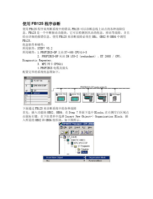
使用FB125程序诊断使用FB125程序来判断系统中的错误,FB125可以诊断总线上站点的各种故障信息。
FB125是一个中断驱动功能块,它可以检测到从站的组态,掉站等故障,并且给出详细的报错信息。
使用FB125来诊断故障必须在OB1, OB82和OB86中调用FB125。
组态软件和硬件:所用软件:STEP7 V5.2所用硬件:1.PROFIBUS-DP主站S7-400 CPU414-32. PROFIBUS-DP从站IM 153-2 (redundant) 、ET 200S / CPU、Diagnostic Repeater。
3. MPI网卡CP56114.PROFIBUS电缆及接头配置完毕的系统组态图如下:下面通过FB125来诊断系统中的各种故障首先,插入功能块OB82、OB86。
在Step 7界面下选中Blocks,在右侧空白区域点击鼠标右键,在下拉菜单中选择Insert New Object-〉Organization Block,插入所需的OB82和OB86组织块,如下图所示。
由于在程序中要使用DB125存储故障信息,所以按照添加OB块的步骤添加OB125。
分别打开OB1,OB82和OB86,在其中调用FB125和DB125,输入程序,例子程序如下:程序为诊断信息分配了存储空间,下面对每条语句的诊断功能做进一步的说明。
----------------------------------------------------------------------以下参数从1-8均为输入量---------------------------------------------------------------------- 1. DP_MASTERSYSTEM (INT)表示配置的DP主站系统的个数,在本例中为1。
2.EXTERNAL_DP_INTERFACE(BOOL)=0,CPU主站的集成DP接口;=1,外部接口,如CP/IM。
DP诊断功能块说明

DP诊断功能块说明附录4:SIMATIC S7的DP诊断功能块说明应⽤PROFIBUS-DP和SIMATIC S7诊断评估远程组态时,⽤户程序可以使⽤两个不同的S7功能块。
如果除了诊断概要外还需要有关总线节点上错误和故障的详细信息,请使⽤功能块FB125。
功能块FC125是⼀个简化版本,它只提供有关“哪些总线节点上发⽣故障或者错误”的信息(诊断概要)。
该功能块不能显⽰详细的信息。
1 FB125和FC125的应⽤领域FB125和FC125可⽤于下列集成的DP接⼝和外部DP接⼝:CPU 313C-2 DPCPU 314C-2 DPCPU 315-2 DP(从6ES7 315-2AF02-0AB0起)CPU315-2DP(仅适⽤于6ES7 315-2AF01-0AB0):不能使⽤FC125FB125不能通过Start/RESET检测到有故障的从站CPU 316-2 DPCPU 318-2 DPC7-626 DP(从6ES7 626-2AG01-0AE3起)C7-633 DP和C7-634 DPSINUMERIK840D带有集成的CPU315-2 DP(6ES7 315-2AF01-0AB0):不能使⽤FC125FB125不能通过Start/RESET检测到有故障的从站SINUMERIK 840DI,带有集成的CPU315-2 DP(6ES7315-2AF03-0AB0)CPU 41x-2/3/4DPCP 443-5IM467和IM467 FOWIN ACWIN LC不适⽤于CP 342-52 FB125诊断功能块FB125通过中断驱动来诊断出错和故障的DP从站。
如果从站出现故障,则显⽰详细的故障原因诊断信息(插槽或模块编号、模块状态、通道编号、通道故障)。
通过单独的诊断,可以读取和解释任何DP从站的诊断信息。
诊断概要给出已组态的、现存的、出错的和发⽣故障的DP从站信息。
当DP/ASI-Link⽤作DP从站时,FB125诊断功能块还能提供下级ASI总线系统的信息。
如何对PROFIBUS DP通信进行诊断?

如何对PROFIBUS DP通信进行诊断?可以查看从站接口模块上代表通信的指示灯判断故障原因。
1.从站接口模块上BF红灯常亮,表示PROFIBUS DP的通信已经中断,需要检查下面几项:①检查至DP 主站的总线电缆是否断开,主站是否上电。
可以通过测量电阻阻值的方法判断DP电缆的通断。
将所有总线连接器从站点上拔下,在一端测量DP电缆中红/绿线之间的阻值。
如果两端终端电阻都置于"On"位置,电阻阻值在110欧姆左右,如果将一端终端电阻置于"Off"位置,电阻阻值在220欧姆左右,如果两端终端电阻都置于"Off"位置,电阻阻值应该是无穷大。
②总线连接器是否已正确插入,电缆连接是否正确,总线连接器上的终端电阻设置是否正确。
错误的接线和终端电阻设置也会导致通信中断。
位于网络终端的总线连接器应该将DP电缆连接在"In"接口上,且终端电阻应该置于"On"位置。
网络中间站点终端电阻应该置于"Off"位置。
图1 DP电缆接线和终端电阻设置③同时如果DP主站上代表通信的指示灯BF/BUSF红灯常亮,说明总线电缆有短路或主站DP端口损坏。
拔掉主站总线连接器,如果变为红灯闪烁,说明是总线电缆有问题,如果还是红灯常亮,就是主站DP端口损坏。
2. 从站接口模块上BF红灯闪烁,表示PROFIBUS DP的通信已经连通但是组态错误,需要检查下面几项:①从站组态的和实际设置的PROFIBUS 地址不一致。
首先,接口模块的PROFIBUS地址要在断电下设置,如果带电设置需要重新上电。
有些型号的接口模块PROFIBUS地址设置DIP开关最下面一个要始终在OFF位置。
②已组态的从站与实际安装不相符。
检查从站安装是否缺少模块或模块有错误,或者是否插入了未组态的模块。
模块版本和安装顺序是否和组态一致。
ET200S子站要检查是否在最后安装了终端模块。
DP网络通信故障的自动诊断

DP网络通信故障的自动诊断作者:***来源:《今日自动化》2022年第04期[摘要]DP网络通信故障对通信安全、通信可靠性等会产生直接的影响。
因此,结合DP网络通信故障自动诊断需求,利用西门子PLC的中断组织块进行诊断与分析,可提高DP网络故障自动诊断与故障分析处理的综合水平。
在故障分析与处理中,则从通信软件分析以及自动诊断的角度,对DP网络的不同故障问题进行快速处理,旨在实现DP网络通信故障的自动诊断与分析水平。
[关键词]DP网络;通信故障;自动诊断[中图分类号]TN915.06 [文献标志码]A [文章编号]2095–6487(2022)04–0–03Automatic Diagnosis of DP Network Communication FaultLiu Xiao-ming[Abstract]DP network communication fault will have a direct impact on communication safety and communication reliability. Therefore, combined with the requirements of automatic diagnosis of DP network communication fault, the comprehensive level of automatic diagnosis and fault analysis of DP network fault can be improved by using the interrupt organization block of Siemens PLC. In the fault analysis and processing, different fault problems of DP network are processed quickly from the perspective of communication software analysis and automatic diagnosis, in order to realize the automatic diagnosis and analysis level of DP network communication fault.[Keywords]DP network; communication failure; automatic diagnosis[摘要]DP网络通信故障对通信安全、通信可靠性等会产生直接的影响。
- 1、下载文档前请自行甄别文档内容的完整性,平台不提供额外的编辑、内容补充、找答案等附加服务。
- 2、"仅部分预览"的文档,不可在线预览部分如存在完整性等问题,可反馈申请退款(可完整预览的文档不适用该条件!)。
- 3、如文档侵犯您的权益,请联系客服反馈,我们会尽快为您处理(人工客服工作时间:9:00-18:30)。
使用FB125程序诊断使用FB125程序来判断系统中的错误,FB125可以诊断总线上站点的各种故障信息。
FB125是一个中断驱动功能块,它可以检测到从站的组态,掉站等故障,并且给出详细的报错信息。
使用FB125来诊断故障必须在OB1, OB82和OB86中调用FB125。
组态软件和硬件:所用软件:STEP7 V5.2所用硬件:1.PROFIBUS-DP主站S7-400 CPU414-32. PROFIBUS-DP从站IM 153-2 (redundant) 、ET 200S / CPU、Diagnostic Repeater。
3. MPI网卡CP56114.PROFIBUS电缆及接头配置完毕的系统组态图如下:下面通过FB125来诊断系统中的各种故障首先,插入功能块OB82、OB86。
在Step 7界面下选中Blocks,在右侧空白区域点击鼠标右键,在下拉菜单中选择Insert New Object-〉Organization Block,插入所需的OB82和OB86组织块,如下图所示。
由于在程序中要使用DB125存储故障信息,所以按照添加OB块的步骤添加分别打开OB1,OB82和OB86,在其中调用FB125和DB125,输入程序,例子程序如下:程序为诊断信息分配了存储空间,下面对每条语句的诊断功能做进一步的说明。
----------------------------------------------------------------------以下参数从1-8均为输入量---------------------------------------------------------------------- 1. DP_MASTERSYSTEM (INT)表示配置的DP主站系统的个数,在本例中为1。
2.EXTERNAL_DP_INTERFACE(BOOL)=0,CPU主站的集成DP接口;=1,外部接口,如CP/IM。
3. MANUAL_MODE (BOOL)=0,自动模式,此模式下不支持单个从站的诊断;=1,手动模式,可以进行单个从站的诊断。
4. SINGLE_STEP_SLAVE (BOOL)转到下一个出错的DP从站。
5. SINGLE_STEP_ERROR(BOOL)转到正在显示的DP从站的下一个错误。
6. RESET (BOOL)=1,复位,初始化系统。
7. SINGLE_DIAG (BOOL)只在手动模式下(MANUAL_MODE=1)有效。
=1,读DP从站的诊断。
可在SINGLE_DIAG_ADR配置该从站的站号。
8. SINGLE_DIAG_ADR (BYTE)只在手动模式下(MANUAL_MODE=1)有效。
与SINGLE_DIAG配合使用,在其中设置单独诊断的从站的站号。
---------------------------------------------------------------------以下参数9-25均为输出量。
--------------------------------------------------------------------- 9.ALL_DP_SLAVES_OK (BOOL)=0,系统中从站存在故障;=1,系统中从站运行正常。
10.SUM_SLAVES_DIAG (BYTE)出错的DP从站的数目。
11. SLAVE_ADR (BYTE)出错的DP从站的站号。
12. SLAVE_STATE (BYTE)错误号 0 1 2 3从站状态 正常 连接从站失败 出错 未组态或无法诊断 13.SLAVE_IDENT_NO (WORD)与SLAVE_ADR有关。
14. ERROR_NO (BYTE)与当前SLAVE_ADR参数指示的从站相对应的错误编号,每个编号都有一个与之相对应的故障信息。
15.ERROR_TYPE (BYTE)编号 功能1 标出故障模块的插槽2 模块状态3 通道诊断,定位当前诊断的模块号,通道号4 S7诊断5 单位诊断,从站的诊断数据可通过数据块的932-1175字节来读出6 电缆诊断,可通过Repeater检测错误位置和原因 16.MODULE_NO (BYTE)与当前SLAVE_ADR参数指示的从站相对应的模块编号,指示出错的从站对应的槽或模块。
17.MODULE_STATE (BYTE)与当前SLAVE_ADR参数指示的从站相对应的模块状态。
编号 0 1 2 3 模块状态 正常 故障 模块不正确 模块缺失 18.CHANNEL_NO (BYTE)与当前SLAVE_ADR参数指示的从站相对应的故障模块的通道编号。
19.CHANNEL_TYPE (BYTE)与当前SLAVE_ADR参数指示的从站相对应的模块中出错通道的类型。
具体的故障信息参见手册P4表格。
20.CHANNEL_ERROR_CODE (INT)与当前SLAVE_ADR参数指示的从站相对应,每一个错误的通道都明确地给出了错误信息,每条信息对应着一个标号,具体标号对应的故障信息参见手册P4-P8表格。
21. CHANNEL_ERROR_INFO_1(DWORD)与当前SLAVE_ADR参数指示的从站相对应,故障通道上的位错误信息,不同的错误信息对应不同的错误类型(ERROR_TYPE)。
ERROR_TYPE=3,通道诊断信息详见手册P8中部表格。
ERROR_TYPE=4,S7诊断信息详见手册P9-P10表格。
22.CHANNEL_ERROR_INFO_2(DWORD)与当前SLAVE_ADR参数下,与上文中ERROR_TYPE中的编号4(S7诊断)相对应,提供了满足S7模块DS0数据记录的特殊错误信息,详见手册P11表格。
23. DIAG_COUNTER (BYTE)显示的诊断DP从站的总数。
24. DIAG_OVERFLOW (BOOL)同时接受诊断的总数大于32个,从站超过了FB125可以处理的上限,需要执行RESET复位。
25. BUSY (BOOL)FB125正在诊断DP系统。
下图为从站编号的分配表。
通过以上两个表格,可以判断出系统中从站的状态,下面通过一个例子来说明。
在编程界面下选择菜单栏中PLC->Monitor/Modify Variables。
点击工具栏中的,观察在线诊断结果。
在23栏中,起始地址为1176字节,已组态的从站为3,4,5,6和16号从站。
在24栏中,起始地址为1192字节,已检测到的从站为3,4和16号从站。
在25栏中,起始地址为1208字节,检测不到的从站为5,6号从站。
在26栏中,起始地址为1224字节,没有故障从站。
在27栏中,起始地址为1240字节,受影响的从站为5,6号从站。
可以看到,通过FB125可以获得一个详细的诊断结果,从故障站点,故障模块,故障通道,逐步明确故障的发生地点;根据故障信息,有助于找出故障原因,从而排除故障。
同时数据存储区可以做为接口被其它程序读取和调用(如WINCC),更直观的找出故障从站和错误信息。
例子程序以及FB125手册见光盘。
如何将 FB125 DP 诊断块中的诊断数据在 WinCC flexible 中可视化?显示订货号6AV661.. WINCC flexible SIMATIC HMI Software6AV662.. WINCC flexible SIMATIC HMI Software 2说明:独立的 Profibus 用户可以从 S7 项目“ DP_DIAxx ”中使用 FB125 诊断块在 Profibus 子网中诊断。
您可以从条目 ID 387257中下载诊断块或者 S7 项目。
( 18 KB )图 01 - 实用原则在以下条目 ID 5362473中您可以找到适用于 ProTool 及 WinCC flexible 上适当的面板的诊断画面。
如果下载中没有相关操作面板,请使用该操作面板前一版本的下载。
或者您可以选择使用 WinCC flexible 库,在本条目的最后可以加载该库。
以下的描述解释了您如何可以将 FB125 及使用 WinCC 库的诊断画面集成到您的项目中。
No.步骤1 打开 STEP 7 管理器•在 STEP 7 中创建一个新项目,并且组态添加所有硬件。
•打开 S7 项目“ DP_DIAxx ”。
•复制 FB125 及 DB125 或者 FC125 到您的项目当中。
•同样的添加 OB82 及 OB86。
( 26 KB )图 02 - S7 块2 在 OB1 中调用功能块 FB125•在循环程序(例如 OB1 )中调用包含 DB125 的 FB125。
•保存并关闭相应的块 - 在样例 OB1 中。
( 6 KB ) ( 19 KB ) ( 23 KB )( 69 KB ) ( 193 KB )( 22 KB ) ( 142 KB ) ( 135 KB )( 135 KB )在附件 1附件FB125附件How is the diagnostic data of the DP diagnostics block FB125 in WinCC flexible visualized?Display part number6AV661.. WINCC flexible SIMATIC HMI Software6AV662.. WINCC flexible SIMATIC HMI Software 2Instructions:Using the diagnostics block FB125 from the S7 project "DP_DIAxx" the individual Profibus users can be diagnosed in a Profibus subnet. You can download the diagnostics block or the S7 project under the following Entry ID 387257.( 18 KB ) Fig. 01 - Functional principle( 26 KB )( 6 KB ) Fig. 03 - Calling FB125( 19 KB ) Fig. 04 - Adding HMI station( 23 KB )( 69 KB ) Fig.06 - Open WinCC flexible library( 193 KB )( 22 KB )( 142 KB ) Fig. 09 - Diagnostics overview( 135 KB )( 135 KB ) Attachment 1:Attachment 2:西门子诊断中继器使用说明Siemens Diagnostic Repeater User Guide摘要 针对诊断中继器的使用方法以及注意事项进行介绍关键词 Profibus,诊断中继器,网络拓扑,等时同步Key Words Profibus,Diagnostic Repeater,Topology,TSNYIA&DT Service & Support Page 2-21目录1 诊断中继器的介绍 (4)1.1 诊断中继器的前面板 (4)1.2 中继器的诊断功能 (5)2 诊断中继器的诊断方法介绍 (6)2.1 时钟信息 (6)2.2 拓扑结构 (7)2.2.1 通过STEP7软件进行网络拓扑诊断 (10)2.2.2 通过用户程序进行网络拓扑诊断 (13)3 诊断缓冲区 (13)3.1 诊断缓冲区信息读取 (13)3.2 等时同步 (15)3.2.1 等时同步的网络设置 (15)3.2.2 等时同步的网络诊断 (17)4 统计缓存 (19)IA&DT Service & Support Page 3-21做为Profibus 网络中继器,诊断中继器不仅提供了中继器的功能,还能够对Profibus网络进行网络诊断和故障定位,这里就诊断中继器的使用做一个介绍。