声表用石英切割方向
sio
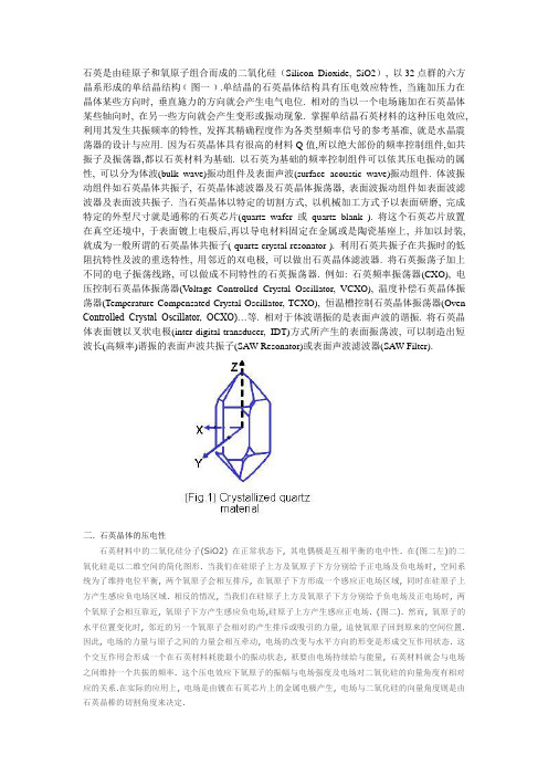
石英是由硅原子和氧原子组合而成的二氧化硅(Silicon Dioxide, SiO2), 以32点群的六方晶系形成的单结晶结构﹝图一﹞.单结晶的石英晶体结构具有压电效应特性, 当施加压力在晶体某些方向时, 垂直施力的方向就会产生电气电位. 相对的当以一个电场施加在石英晶体某些轴向时, 在另一些方向就会产生变形或振动现象. 掌握单结晶石英材料的这种压电效应, 利用其发生共振频率的特性, 发挥其精确程度作为各类型频率信号的参考基准, 就是水晶震荡器的设计与应用. 因为石英晶体具有很高的材料Q值,所以绝大部份的频率控制组件,如共振子及振荡器,都以石英材料为基础. 以石英为基础的频率控制组件可以依其压电振动的属性, 可以分为体波(bulk wave)振动组件及表面声波(surface acoustic wave)振动组件. 体波振动组件如石英晶体共振子, 石英晶体滤波器及石英晶体振荡器, 表面波振动组件如表面波滤波器及表面波共振子. 当石英晶体以特定的切割方式, 以机械加工方式予以表面研磨, 完成特定的外型尺寸就是通称的石英芯片(quartz wafer 或quartz blank ). 将这个石英芯片放置在真空还境中, 于表面镀上电极后,再以导电材料固定在金属或是陶瓷基座上, 并加以封装, 就成为一般所谓的石英晶体共振子( quartz crystal resonator ). 利用石英共振子在共振时的低阻抗特性及波的重迭特性, 用邻近的双电极, 可以做出石英晶体滤波器. 将石英振荡子加上不同的电子振荡线路, 可以做成不同特性的石英振荡器. 例如: 石英频率振荡器(CXO), 电压控制石英晶体振荡器(Voltage Controlled Crystal Oscillator, VCXO), 温度补偿石英晶体振荡器(Temperature Compensated Crystal Oscillator, TCXO), 恒温槽控制石英晶体振荡器(Oven Controlled Crystal Oscillator, OCXO)…等. 相对于体波谐振的是表面声波的谐振. 将石英晶体表面镀以叉状电极(inter-digital-transducer, IDT)方式所产生的表面振荡波, 可以制造出短波长(高频率)谐振的表面声波共振子(SAW Resonator)或表面声波滤波器(SAW Filter).二. 石英晶体的压电性石英材料中的二氧化硅分子(SiO2) 在正常状态下, 其电偶极是互相平衡的电中性. 在(图二左)的二氧化硅是以二维空间的简化图形. 当我们在硅原子上方及氧原子下方分别给予正电场及负电场时, 空间系统为了维持电位平衡, 两个氧原子会相互排斥, 在氧原子下方形成一个感应正电场区域, 同时在硅原子上方产生感应负电场区域. 相反的情况, 当我们在硅原子上方及氧原子下方分别给予负电场及正电场时, 两个氧原子会相互靠近, 氧原子下方产生感应负电场,硅原子上方产生感应正电场. (图二). 然而, 氧原子的水平位置变化时, 邻近的另一个氧原子会相对的产生排斥或吸引的力量, 迫使氧原子回到原来的空间位置. 因此, 电场的力量与原子之间的力量会相互牵动, 电场的改变与水平方向的形变是形成交互作用状态. 这个交互作用会形成一个在石英材料耗能最小的振动状态, 祇要由电场持续给与能量, 石英材料就会与电场之间维持一个共振的频率. 这个压电效应下氧原子的振幅与电场强度及电场对二氧化硅的向量角度有相对应的关系.在实际的应用上, 电场是由镀在石英芯片上的金属电极产生, 电场与二氧化硅的向量角度则是由石英晶棒的切割角度来决定.三.石英的切割角度依据不同的应用领域及工作温度需求, 因应了许多不同的石英切割角度种类. 例如AT-, BT-, CT-, DT-, NT, GT…..等不同的切割板片. 不同的切割方向的板片具有不同的弹性常数张量(elastic constant tensor), 不同的压电常数张量(piezoelectric constant tensor)及不同的介电常数张量(dielectric constant tensor). 这些张量在石英组件的设计及应用上展现了不同的振荡及温度特性. (图三)表现了在Z-plat石英结构上,几种不同方向的石英板片切割方式四.石英晶体的振动模态六.石英晶体共振子的等效线路及参数图七)(a)及(b)分别是DIP型式及SMD型式的石英振荡子的基本结构图. (图七)(c)是电子电路上所使用代表石英振荡子的电子符号. 当石英晶体共振子处在远离振荡频率区域时, 石英晶体共振子仅是一个电容性的组件, 当频率接近石英晶体的振荡频率时, 就接近是一个电感性的等效LCR振荡线路.(图八) 就是将石英晶体共振子转换成振荡频率附近的Butterworth-Van Dyke (BVD)等效电路. 在这个图中, 有四个主要参数: 静态电容-Co, 动态电容-C1, 动态电感-L1及动态电阻-R1.七.共振频率( Resonance Frequency )在技术文献及产品应用上, 石英晶体共振子的共振有三组不同定义及特性的共振频率.(1) 串联谐振频率及并联谐振频率 ( fs , fp )(series resonance frequency and parallel resonance frequency)(2) 谐振频率及反谐振频率 ( fr , fa )(resonance frequency and anti-resonance frequency)(3) 最大电导频率及最小电导频率 ( fm , fn )八.名词(1) 公称频率及容许误差( Nominal Frequency and Tolerance )在正确的振荡线路匹配下, 从振荡线路输出的频率, 称之为“公称频率( nominal frequency )”. 频率单位一般是以兆赫( megahertz, MHz) 或 仟赫(Kilohertz, KHz)表示.实际的批量生产及振荡线路应用上, 产品在室温环境(25o C)中都会有一些相对于中心频率的频率散布误差. 这类型的频率容许误差的最大散布值,一般是以ppm ( parts per million )或% ( percent ) 来表示.(2) 基本波振荡及倍频振荡模态( Fundamental and Overtone Vibrations Mode )在AT 切割角度的石英晶体共振子主要是以厚度剪切振荡模态存在. 石英晶体在共振时, 除了基本波振荡之外, 高阶的倍频共振也与基本波振荡同时存在于石英晶体的电极区域之间. 但是, 由于压电材料的电极是电气相位相反的振动环境, 所以, 祇有奇数倍(odd number)的高频倍频可以发生, 偶数倍(even串联偕振频率及并联偕振频率, fs and fp ,是分别由电导(real part of the admittance)最大和阻抗(real part of the electric input impedance)最大时的频率.谐振频率及反谐振频率, fr and fa , 分别是当电导等于零(纯电阻特性)的二个频率. 在这个时候, fr 的阻抗为 1 / Rr 而fa 的阻抗为 1/ Ra.在评估共振时的等效线路时, 串联谐振频率及并联谐振频率, fs and fp , 是最重要的二个频率参数. 对于串联谐振频率及并联谐振频率( fs and fp )二者的关系, 我们可以用下列公式来表达:公式中的C1及 L1 分别是(图七)中的动态电容(motional capacitance)及动态电感(motional conductance); Co 是静态电容(shunt capacitance).number)的倍频共振在石英晶体共振子是不会存在的(图十).(Fig.10) Only odd number harmonic vibrations can be excited in crystal resonator (3) 负载电容( Load Capacitance, CL )振荡线路上的”负载电容(load capacitance)”定义为:从石英晶体共振子的两个端子看向振荡线路所遭遇到的所有电容值. 负载电容在线路上可以与石英晶体共振子以并联(parallel)或以串联(series)的方示连接. 以并联方式连接的振荡线路中, 负载电容(CL)的大小会影响公称频率的特性.这种负载电容并联线路的共振频率以f L表示:(4) 频率对温度稳定性( Frequency-Temperature Stability )石英频率因温度变化而改变, 这是因起于石英材料在各个坐标轴向的热膨胀系数不同, 当温度变化时, 各轴向晶格距产生些许变化. 当引用不同的切割角度时, 不同振荡模态的之变化也会不同.以AT切割角度的厚度剪切振荡模态的设计, 一般是采用摄氏25度作为参考温度点的频率来定义在工作环境温度范围内的频率变动的稳定性. 在定义这项频率对温度稳定性参数的同时, 也应该一同规范出相对应的工作环境温度范围(Operation Temperature Range)石英频率组件频率对温度稳定性的特性, 亦如同公称频率误差一样, 是以ppm或是以% 为计量单位. 组件的频率温度特性曲线与石英的切割角度, 振荡模态, 表面处理及外型尺寸都有很大的关系. 除此之外, 振荡线路上的负载电容(CL), 驱动功率(drive level)的特性, 也会影响到振荡线路输出频率对温度变化的稳定性.(5) 等效串联阻抗( Equivalent Series Resistance , ESR)当石英晶体串联振荡在fs时, C1及L1是相反相位而互相抵消, 整个共振子的动态支臂(motional arm) 的导纳(admittance)是接近最小阻抗值R1. 这时候整个石英晶体共振子的表现仅是一个电阻性的组件. 电阻值R1是整个组件的机械性能量损耗. 其中包含了石英材料, 接着材料及封装材料上所有的能量损耗.(6) 动态电容( Motional Capacitance C1 ) 及动态电感( Motional Inductance L1 )在公式一中, ,动态电容C1及动态电感L1与串联偕振频率, fs ,是相互关联的.在实际的量测系统中, 我们祇能量测到动态电容C1及串联协振频率fs . 动态电感L1是由公式(4)计算得到.(7) 静态电容( Static Capacitance or Shunt Capacitance, Co )静态电容,Co, 主要来自由以石英芯片为介电材料与两个电极所形成的电容为主; 另外一小部份的静态电容来自连接石英芯片与接线的导电接着材料之间的电容和封装外壳的电容.静态电容是在远低于振荡频率的范围量测出来的, 以避免在受到振荡频率附近的动态电容影响. 公式(5) 是静态电容的数学表示式.在公式(5)中, A代表电极的面积; d代表石英芯片的厚度; ε是石英芯片的相对应介电值; Cm+p是其它由材料产生的电容值(8) 驱动功率( Drive Level )石英晶体的驱动功率是指石英晶体共振子的消耗功率. 一般是以微瓦(microwatt)表示. 振荡线路的设计上必须提供适当的功率让石英晶体共振子开始起振并维持振荡. 石英晶体的振荡是属于物理上的高频机械振动, 振荡时的电气阻抗值约在10~100奥姆以下( 依频率范围及尺寸大小有差异). 振荡线路若提供过高的驱动功率, 会使石英晶体的非线性特性变化及石英/电极/接着材料的接口恶化, 进而造成振荡频率FL及等效阻抗R1的过度变化. 石英晶体在长时期的过高驱动功率下工作, 会有不稳定的现象. 随着各类应用面的低消耗功率需求及产品小形化趋势, 加上近几年石英产品的技术大幅提升, 石英晶体共振子的电气阻抗值整体都下降而且稳定. 振荡线路的设计不需要,也不应该提供过高的驱动能量在石英晶体共振子上面. 对于绝大部份的应用面而言, 振荡线路提供10 ~ 100 微瓦(microwatt)的最大功率(视石英共振子的尺寸及频率而定)给石英共振子已足够了.(9) 电气品质因子( Quality Factor, Q )对于石英晶体共振子, 电气质量因子Q是很重要的一个特性. 电气质量因子可以用下列公式(6)表示石英晶体的共振子的质量因子可以达到数佰万以上.(10) 牵引率( Pullability ) 及敏感度( Trim Sensitivity )石英晶体共振子应用在并联振荡线路上, 振荡频率与负载电容CL有很大的关系. 这在前面的公式(3)就可以看到. (图十一) 是以并联振荡线路上FL频率对负载电容CL的变化曲线示意图.频率的“牵引率”指的是负载电容CL1的频率FL1到负载电容CL2的频率FL2的频率变化. 在(图十一)中可以是FL1(CL=24pF)与FL2(CL=10pF)的频率变化值. 在这个例子中的频率牵引率是220 ppm. 若我们将CL1与CL2的负载电容值趋近极小化(曲线作数学上的微分), 就会得到曲线的切线值. 这个切线值就是用某一个负载电容的敏感度( trim sensitivity ).在(图十一)中, CL=24 pF 时的频率敏感度是10 ppm/pF, 及CL=10 pF时的频率敏感度是20 ppm/pF. 在并联线路中, 负载电容越小, 频率对负载电容变化的敏感度越高. 相反的, 负载电容越大, 频率对负载电容变化的敏感度越低. 这就是石英晶体共振子用于VCXO线路上时, 线路设计上会选用较小负载电容. 反之, 在要求较准确的频率信号时, 线路设计上会选用较高的负载电容.(Fig. 11) Frequency variation vs. load capacitance(11) 老化( AGING )“老化”顾名思意就是指在某一段特定时间范围内, 石英晶体共振子随时间的频率变化, 以百万分之一( parts per million, ppm ) 为表示的单位. 老化在频率与时间上的特性曲线, 一般是呈现指数(exponential)型态的变化. 频率老化变动最大的期间是在石英频率组件制成后的第一个月. 之后, 频率的变化就随时间逐渐减少. 频率的老化特性有好几个主要的因素影响. 比如说, 封装的方法, 材料的种类, 制程温度, 制程管控, 热处理过程及产品的尺寸和频率高低. 在规格上大多都要定义出短期(1~3个月) 或长期(1~10年)的频率老化需求.(12) 储存温度范围( STORAGE TEMPERATURE RANGE )除了在前面的工作环境温度范围之外, 另一项与温度有关的特性是”储存温度范围(Storage Temperature Range)”. 这个参数指的是产品在静态状况下可以储存的最高与最低温度范围. 在这个温度范围内, 产品必需保证在长时期的储存后, 还是可以在工作温度范围内正常的工作并符合规格. 这项特性与石英晶体共振子的组件设计及制程设计有很大关系, 要小心的定义.(13) 负性阻抗(Negative Resistance , - R )负性阻抗是指从石英晶体共振子的二个端子往振荡线路看过去, 所遭遇到振荡线路在振荡频率时的阻抗特性值. 振荡线路上必需提供足够的放大增益值来补偿石英晶体共振子在共振时的机械能损失. 负性阻抗并不是石英振荡子的产品参数, 却是振荡线路的一项重要特性参数. 从共振子的角度而言, 就是在振荡线路的”负性阻抗”.九.石英晶体发振器( CRYSTAL OSCILLATORS )当把石英共振子与振荡线路或集成电路(IC)一起整合在一个封装内, 由外部提供电源电压, 形成一个主动组件输出频率信号, 就是所谓的石英晶体振荡器. 石英晶体振荡器可以藉由单一封装组件内部不同的振荡线路及输出线路, 提供不同特性需求的参考频率(reference frequency). 例如有石英频率振荡器SPXO ( Simple Package Crystal Oscillator ) 或称为CXO ( Clock Crystal Oscillator ), 可程序化石英晶体振荡器PCXO ( Programmable Crystal Oscillator ), 电压控制石英晶体振荡器VCXO ( V oltage Controlled Crystal Oscillator ), 温度补偿石英晶体振荡器TCXO ( Temperature Compensated Crystal Oscillator ) 及恒温槽控制石英晶体振荡器OCXO ( Oven Controlled Crystal Oscillator ).为了满足应用面需求而言, 石英晶体振荡器内部的振荡线路有以基本波或三倍频不同方式. 若要达到数佰兆赫的输出频率时, 振荡线路后级可以采用锁相回路方式或倍频方式, 将较低频率的石英振荡频率提升. 对于输出端的输出准位及输出波形也有各类不同需求, 如CMOS, LVPECL, LVDS…..等. 这些规格都要仔细的定义.上个世纪的70年代,芯片封装基本都采用DIP(Dual ln-line Package,双列直插式封装)封装,此封装形式在当时具有适合PCB(印刷电路板)穿孔安装,布线和操作较为方便等特点。
at切石英晶体的系数
at切石英晶体的系数切割石英晶体是一项非常重要的工艺,它是将石英晶体切割成各种形状和尺寸的关键步骤。
而在进行石英晶体的切割过程中,需要考虑到很多因素,其中之一就是石英晶体的系数。
石英晶体的系数是指石英晶体在不同方向上的物理性质和特性。
这些系数可以用来描述石英晶体的光学、电学和机械性能。
在进行石英晶体的切割时,了解和掌握这些系数是非常重要的,因为它们可以帮助我们选择合适的切割方向和切割角度,从而得到所需的形状和尺寸。
石英晶体的系数包括线性热膨胀系数、弹性系数、介电常数、光学旋光度等。
其中,线性热膨胀系数是指石英晶体在温度变化时长度变化的比例。
而弹性系数则是指石英晶体在外力作用下变形的程度。
介电常数是指石英晶体在电场作用下的电极化程度。
光学旋光度则是指石英晶体在光线传播过程中旋转光线偏振面的程度。
石英晶体的系数与其晶体结构和化学成分密切相关。
一般来说,石英晶体的系数在不同方向上具有各向异性,即不同方向上的系数数值不同。
这是由于石英晶体的结构呈现出六角形的对称性,导致其物理性质在不同方向上有所差异。
在进行石英晶体的切割时,我们需要根据具体应用需求选择合适的切割方向和切割角度。
例如,在制作石英晶体振荡器时,我们通常选择将石英晶体切割成某个特定角度的平板形状,以便实现所需的振荡频率。
而在制作石英晶体滤波器时,则需要根据滤波器的工作原理选择合适的切割方向和切割角度。
除了系数外,还有一些其他因素也会影响石英晶体的切割过程和结果。
例如,切割工艺参数(如刀具材料、切割速度、切割液等)、切割设备的精度和稳定性、切割工艺的操作技术等。
这些因素都需要我们进行综合考虑和优化,以确保最终得到符合要求的石英晶体产品。
总之,石英晶体的系数是进行石英晶体切割过程中需要考虑到的重要因素之一。
了解和掌握这些系数可以帮助我们选择合适的切割方向和切割角度,从而得到所需的形状和尺寸。
同时,还需要综合考虑其他因素,如切割工艺参数、设备精度和稳定性等,以确保最终得到高质量的石英晶体产品。
声表滤波器的阻抗匹配分析
声表滤波器的阻抗匹配分析黎静【摘要】为了提升声表滤波器在射频电路中的性能,除了优化声表滤波器自身的性能外,其与外部电路的阻抗匹配也是相当重要的.本文基于实现声表滤波器在射频电路中性能最大化利用的目的,总结与归纳了一些常用的声表滤波器在射频电路中的阻抗匹配方法,也提出了两种射频电路中不平衡转平衡的阻抗匹配方法,并对它们作了ADS仿真验证,仿真表明该方法确实能提升滤波器在电路中的性能,从而使整个电路的相关性能得以优化.%In order to improve the SAW filter performance in the RF circuit,in addition to optimizing the performance of the SAW filter itself,and its external circuit impedance matching is also very important.In this paper,based on the realization of the SAW filter in the RF circuit to maximize the use of the purpose of summing up and summed up some commonly used SAW filter in the RF circuit impedance matching method,also proposed two RF circuit unbalanced The simulation results show that this method can improve the performance of the filter in the circuit,so that the correlation performance of the whole circuit can be optimized.【期刊名称】《电子设计工程》【年(卷),期】2018(026)001【总页数】4页(P118-121)【关键词】声表滤波器;射频;阻抗匹配;不平衡转平衡;ADS【作者】黎静【作者单位】武汉邮电科学研究院湖北武汉430074;深圳市虹远通信有限责任公司广东深圳518055【正文语种】中文【中图分类】TN99随着移动通信的快速发展,声表滤波器的应用范围不断扩展,由于系统应用的深入,对声表滤波器的性能也提出了更高的要求。
石英晶体微天平的基本原理和具体应用
流体通过剪切模式的声波传感器装置示意图
Liquid flow cell
70 uL flow through reservoir 1 ml static reservoir O-ring seal Resists harsh chemicals Low stress design
Static cell
x轴(电轴):沿x轴方 向或沿y轴方向施加压力 (或拉力)时,在x轴方 向产生压电效应。
y轴(机械轴):沿y轴方 向或沿x 轴方向施加压力 (或拉力)时,在y轴方 向不产生压电效应,只 产生形变。
天然右旋石英晶体晶轴的分布
石英晶体有天然的和人工培育的。 天然石英晶体产量有限,而且大部分都存 在各种缺陷。 石英晶体常见的缺陷:
ΔF = - 2 F02ΔM/A(qq)1/2
ΔF:石英晶体的频率改变量,又称频移值 (Hz);F0:石英晶体的基频;ΔM:沉积在 电极上的物质的质量改变(g);A:工作电 极的面积; q:剪切参数(2.951010 kg·m-1·s-2); q:石英的密度(2648 kg·m-3)。
可以看出,频移值ΔF与质量改变ΔM之间有一简 单的线性关系,负号表示质量升高,频率降低。
AT- 和 BT-切割模式
四、石英晶体微天平(QCM)的 工作原理
石英晶体微天平由一薄的石英圆片和覆盖其表 面的电极组成 。 外加电压加到压电材料上引起一个内在的机械 振动。因为QCM是压电的,振荡电场横着通 过装置产生一个声学波。
1. Quartz crystal 2. 2. Electrode material
QCM crystal. Grey=quartz, yellow=metallic electrodes.
一、石英晶体的结构
压电效应

压电效应压电效应压电式传感器是基于某些物质的压电效应原理工作的。
这些物质在沿一定方向受到压力或拉力作用而发生变形时,其表面上会产生电荷;若将外力去掉时,它们又重新回到不带电的状态,这种现象称为压电效应。
具有这种压电效应的物体称为压电材料或压电元件。
常见的压电元件有石英、钛酸钡、锆钛酸铅等。
图9-1所示为天然结构的石英晶体,呈六角形晶柱。
在直角坐标系中,Z轴表示其纵向轴,称为光轴;X轴平行于正六面体的棱线,称为电轴,Y轴垂直于正六面体棱面,称为机械轴。
常将沿电轴(X轴)方向的力作用下产生的电荷效应称为“纵向压电效应”;沿机械轴(Y轴)方向的力作用下产生电荷的压电效应称为“横向压电效应”;在光轴(Z轴)方向受力时则不产生压电效应。
从晶体上沿轴线切下的薄片称为晶体切片,图9-2即为石英晶体切片的示意图。
在每一切片中,当沿电轴方向加作用力Fx时,则在与电轴垂直的平面上产生电荷Qx,它的大小为(9-1)式中,d11为压电系数(C/g或 C/N)。
电荷Qx的符号视Fx是受压还是受拉而决定,由式(9-1)中可见,切片上产生电荷的多少与切片几何尺寸无关。
若在同一切片上作用的力是沿着机械轴(Y轴)方向的,其电荷仍在与X轴垂直的平面上出现,而极性方向相反,此时电荷的大小为( 9-2)式中,a、b为晶体切片的长度和厚度,d12为Y轴方向受力时的压电系数(石英轴对称,)。
由式(9-2)可见,沿机械轴方向的力作用在晶体上时产生的电荷与晶体切片的尺寸有关。
式中的负号说明沿Y轴的压力所引起的电荷极性与沿X轴的压力所引起的电荷极性是相反的。
晶体切片上电荷的符号与受力方向的关系可用图9-3表示,图(a)是在X轴方向上受压力,(b)是在X轴方向受拉力,(c)是在Y轴方向受压力,(d)是在Y轴方向受拉力。
在片状压电材料的两个电极面上,如加以交流电压,压电片能产生机械振动,即压电片在电极方向上有伸缩的现象。
压电材料的这种现象称为“电致伸缩效应”,亦称为“逆压电效应”。
声表滤波器和声表谐振器的作用与差别
声表滤波器和声表谐振器的作用与差别声表滤波器(通常简称SAW)主要作用原理是利用压电材料的压电特性,利用输入与输出换能器(Transdu cer)将电波的输入信号转换成机械能,经过处理后,再把机械能转换成电的信号,以达到过滤不必要的信号及杂讯,提升收讯品质的目标。
声表滤波器和声表谐振器被广泛应用在各种无线通讯系统、电视机、录放影机及全球卫星定位系统接收器上替代LC谐振电路,用于级间耦合和滤波。
主要功用在於把杂讯滤掉,比传统的LC 滤波器安装更简单、体积更小。
其缺点是插入损耗比LC谐振电路大晶振全称为晶体振荡器,其作用在于产生原始的时钟频率,这个频率晶振经过频率发生器的放大或缩小后就成了电脑中各种不同的总线频率。
以声卡为例,要实现对模拟信号44.1kHz或48kHz的采样,频率发生器就必须提供一个44.1kHz或48kHz的时钟频率。
如果需要对这两种音频同时支持的话,声卡就需要有两颗晶振。
但是娱乐级声卡为了降低成本,通常都采用SR C将输出的采样频率固定在48kHz,但是SRC会对音质带来损害,而且现在的娱乐级声卡都没有很好地解决这个问题。
晶振一般叫做晶体谐振器,是一种机电器件,是用电损耗很小的石英晶体经精密切割磨削并镀上电极焊上引线做成。
这种晶体有一个很重要的特性,如果给它通电,它就会产生机械振荡,反之,如果给它机械力,它又会产生电,这种特性叫机电效应。
他们有一个很重要的特点,其振荡频率与他们的形状,材料,切割方向等密切相关。
由于石英晶体化学性能非常稳定,热膨胀系数非常小,其振荡频率也非常稳定,由于控制几何尺寸可以做到很精密,因此,其谐振频率也很准确。
根据石英晶体的机电效应,我们可以把它等效为一个电磁振荡回路,即谐振回路。
他们的机电效应是机-电-机-电..的不断转换,由电感和电容组成的谐振回路是电场-磁场的不断转换。
晶振的使用要求
个寄存器与每个石英晶体相关联,一个计数器(counter)和一个保持寄存器 (holdingregister)。石英晶体的每次振荡使计数器减 1。当计数器减为 0 时,产生一 个 中 断 ,计 数 器 从 保 持 计 数 器 中 重 新 装 入 初 始 值 。这 种 方 法 使 得 对 一 个 计 时 器 进 行 编 程,令其每秒产生 60 次中断(或者以任何其它希望的频率产生中断)成为可能。每次 中断称为一个时钟嘀嗒(clocktick)。
谐波
谐波分量功率 Pi 与载波功率 P0 之比,用 dBc 表示。
频率老 化
在规定的环境条件下,由于元件(主要是石英谐振器)老化而引起的输出频率 随时间的系统漂移过程。通常用某一时间间隔内的频差来量度。对于高稳定晶 振,由于输出频率在较长的工作时间内呈近似线性的单方向漂移,往往用老化 率(单位时间内的相对频率变化)来量度。
晶振在电气上可以等效成一个电容和一个电阻并联再串联一个电容的二端网络, 电 工 学 上 这 个 网 络 有 两 个 谐 振 点 ,以 频 率 的 高 低 分 其 中 较 低 的 频 率 为 串 联 谐 振 ,较 高 的 频 率 为 并 联 谐 振 。由 于 晶 体 自 身 的 特 性 致 使 这 两 个 频 率 的 距 离 相 当 的 接 近 ,在 这 个 极窄的频率范围内,晶振等
晶振 经 过 频 率 发 生 器 的 放 大 或 缩 小 后 就 成 了 电 脑 中 各 种 不 同 的 总 线 频 率 。以 声 卡 为 例 ,要 实现对模拟信号 44.1kHz 或 48kHz 的采样,频率发生器就必须提供一个 44.1kHz 或 48kHz 的时钟频率。如果需要对这两种音频同时支持的话,声卡就需要有两颗晶振。 但是娱乐级声卡为了降低成本,通常都采用 SRC 将输出的采样频率固定在 48kHz,但 是 SRC 会对音质带来损害,而且现在的娱乐级声卡都没有很好地解决这个问题。 晶 振 一 般 叫 做 晶 体 谐 振 器 ,是 一 种 机 电 器 件 ,是 用 电 损 耗 很 小 的 石 英 晶 体 经 精 密 切 割 磨 削 并 镀 上 电 极 焊 上 引 线 做 成 。这 种 晶 体 有 一 个 很 重 要 的 特 性 ,如 果 给 它 通 电 ,它 就 会 产生机械振荡,反之,如果给它机械力,它又会产生电,这种特性叫机电效应。他们 有 一 个 很 重 要 的 特 点 ,其 振 荡 频 率 与 他 们 的 形 状 ,材 料 ,切 割 方 向 等 密 切 相 关 。由 于 石 英 晶 体 化 学 性 能 非 常 稳 定 ,热 膨 胀 系 数 非 常 小 ,其 振 荡 频 率 也 非 常 稳 定 ,由 于 控 制 几何尺寸可以做到很精密,因此,其谐振频率也很准确。根据石英晶体的机电效应, 我们可以把它等效为一个电磁振荡回路,即谐振回路。他们的机电效应是机-电-机电..的不断转换,由电感和电容组成的谐振回路是电场-磁场的不断转换。在电路中 的应用实际上是把它当作一个高 Q 值的电磁谐振回路。由于石英晶体的损耗非常小, 即 Q 值非常高,做振荡器用时,可以产生非常稳定的振荡,作滤波器用,可以获得非 常稳定和陡削的带通或带阻曲线。
SAWF(声表面滤波器),特点及用途
什么是SAWF(声表面滤波器),特点及用途(2009-08-01 10:44:52)转载标签:声表滤波器振荡器晶振杂谈什么是SAWF(声表面波滤波器)声表面波滤波器是利用石英、铌酸锂、钛酸钡晶体具有压电效应的性质做成的。
所谓压电效应,即是当晶体受到机械作用时,将产生与压力成正比的电场的现象。
具有压电效应的晶体,在受到电信号的作用时,也会产生弹性形变而发出机械波(声波),即可把电信号转为声信号。
由于这种声波只在晶体表面传播,故称为声表面波。
声表面波滤波器的英文缩写为SAWF,声表面波滤波器具有体积小,重量轻、性能可靠、不需要复杂调整。
在有线电视系统中实现邻频传输的关键器件。
声表面波滤波器的特点是:(1)频率响应平坦,不平坦度仅为±0.3-±0.5dB,群时延±30-±50ns。
(2)SAWF矩形系数好,带外抑制可达40dB以上。
(3)插入损耗虽高达25-30dB,但可以用放大器补偿电平损失。
声表面波滤波器包括声表面波电视图像中频滤波器、电视伴音滤波器、电视频道残留边带滤波器。
声表面波滤波器的典型技术指标如下表所示。
声表面滤波器封装的分类插件型和贴片型(具体的图片如下图声表面波滤波器的应用及发展1 前言声表面波—SAW(SurfaceAcousticWave)就是在压电基片材料表面产生和传播、且振幅随深入基片材料的深度增加而迅速减少的弹性波。
SAW滤波器的基本结构是在具有压电特性的基片材料抛光面上制作两个声电换能器——叉指换能器(IDT)。
它采用半导体集成电路的平面工艺,在压电基片表面蒸镀一定厚度的铝膜,把设计好的两个IDT的掩膜图案,利用光刻方法沉积在基片表面,分别作为输入换能器和输出换能器。
其工作原理是输入换能器将电信号变成声信号,沿晶体表面传播,输出换能器再将接收到的声信号变成电信号输出。
2 SAW滤波器的特点SAW滤波器的主要特点是设计灵活性大、模拟/数字兼容、群延迟时间偏差和频率选择性优良(可选频率范围为10MHz~3GHz)、输入输出阻抗误差小、传输损耗小、抗电磁干扰(EMI)性能好、可靠性高、制作的器件体小量轻,其体积、重量分别是陶瓷介质滤波器的1/40和1/30左右,且能实现多种复杂的功能。
- 1、下载文档前请自行甄别文档内容的完整性,平台不提供额外的编辑、内容补充、找答案等附加服务。
- 2、"仅部分预览"的文档,不可在线预览部分如存在完整性等问题,可反馈申请退款(可完整预览的文档不适用该条件!)。
- 3、如文档侵犯您的权益,请联系客服反馈,我们会尽快为您处理(人工客服工作时间:9:00-18:30)。
A Review of the Recent Development of Temperature Stable Cuts ofQuartz for SAW ApplicationsC.S. Lam, Chris Y.J. Wang and S.M. WangTXC Corporation, Ping Cheng City, Taoyuan County, TaiwanAbstractQuartz continues to be used widely in frequency control applications due to its temperature stability and low cost. In specific, ST-cut quartz provides the best performance in narrow band SAW filter, SAW resonator, SAW oscillator, clock and data recovery unit, frequency translator, etc. Since the discovery of the even more stable LSAW-based quartz LST-cut in 1985, a few more new quartz cuts based on LSAW, HVPSAW, etc. were introduced and some of them were actually being used in telecom SAW products. This paper reviews the development of these temperature stable quartz cuts for SAW applications in the past and discusses possible future development.I. IntroductionQuartz continues to be used widely in frequency control applications due to its temperature stability and low cost. From the early application of ST-cut of quartz for SAW products, many more new cuts were introduced. We first review the linkage of BAW and SAW through the discussion of singly-rotated AT-cut quartz plate, doubly-rotated SC-cut quartz plate, SAW on ST-cut quartz wafer, and STW on singly-rotated quartz wafer. We then review the development of the LST-cut, K-cut and in-plane rotated 33° Y-cut of quartz. The recent development of HVPSAW on quartz is discussed in the end.II. BAW and SAWFor many years, researchers of acoustic wave devices for electronics applications seem to be separated into two camps- the BAW group (or sometimes called the “crystal” group) and the SAW group, and they don’t seem to “mingle.” BAW researchers are most familiar with the AT- and SC-cut thickness-shear quartz resonators. AT-cut is a singly-rotated Y-cut quartz plate (a Y-cut plate has its normal axis parallel to Y-axis) with θ≅ 35.25º (Fig. 1). SC-cut is a doubly-rotated Y-cut with θ≅ 33.93º and Φ≅ 21.93º. In a way, one can use the “BAW Angles” (Φ, θ, ψ) to describe exactly a BAW plate. ψ is in general meaningless to a BAW plate as its vibration is “bulk” in nature (frequency α 1/thickness) with wave traveling across the thickness and the particle motion is in the X-axis direction. The current authors noted some in the industry began to use the term BAWR to mean FBAR (film bulk acoustic resonator). The BAW technology in this paper retains its conventional meaning. SAW researchers instead are most familiar with using the Euler Angles (λ, µ, θ) to describe specific SAW cut and propagation direction. The most popular quartz cut is the ST-cut (ST = Temperature Stable) which has Euler Angles (0º, 132.75º, 0º). It is sometimes called the “X-propagation rotated Y-cut direction.” The Euler Angles (λ, µ, θ) can be related to the BAW Angles (Φ, θ, ψ) byλ = Φµ = θ + 90ºθ = -ΨAnd so ST-cut quartz for SAW is basically an “AT-cut BAW plate” with θ = 42.75º and the SAW propagates in the X-axis. The BAW Angles are (0º, 42.75º, 0º). Any off X-axis SAW propagation can then be described by a non-zero Ψ (e.g. NSPUDT cut of quartz has Ψ≅±25º). Understanding the BAW Angles and Euler Angles allows one intuitively to link the BAW and SAW technologies.Fig. 1 Singly- and Doubly-Rotated Y-Cut Quartz Plates Though limited to low frequency applications, AT- and SC-cuts exhibit cubic frequency-change vs temperature (∆f/f vs T). Depend on the temperature range of operation, BAW resonators can offer ∆f/f stability anywhere between 10 to 100 ppm. ST-cut exhibits quadratic ∆f/f vs T with a 2nd order temperature coefficient of ~–0.034(T-To)2 where To is the turnover temperature (TOT). Assuming the temperature range of operation is –40 to 85ºC and the TOT is well centered at 22.5ºC, the ∆f/f is at least ~130 ppm. Changing the angle θin Fig. 1 (away from 42.75º) can shift the TOT but it doesn’t improve the temperature coefficient. In the mid-70’s, SAW researchers noted Surface Skimming Bulk Wave (SSBW) withψX Z XZ horizontal shearing particle motion can be efficiently excited with SAW transducers aligned with θ ≅ 36º and ψ = ±90º equivalent to Euler Angles (0º, 126º, ±90º). It is also referred as Z’-propagation rotated Y-cut direction. SSBW became Surface Transverse Wave (STW) when well trapped by the periodic structure of the transducers. This wave travels at ~1.6 times of the SAW velocity in the regular ST-cut such that it is convienent for high frequency operation. Unfortunately, the quadratic ∆f/f vs T has higher 2nd order temperature coefficient of ~–0.052(T-To)2. Hence for many years, SAW technology though can be used in high frequency products, it doesn’t offer as stable frequency-temperature performance as the BAW technology.Fig. 2 ∆f/f vs T of AT- and BT-Cut QuartzBAW researchers are also familiar with BT-cut of quartz with BAW Angles (0º, -49º, 0º). Since the thickness-shear velocity is lower than that of the AT-cut’s, BT-cut is sometimes used when one prefers to process thicker plate of the same frequency. BT-cut doesn’t has as good frequency-temperature performance since its ∆f/f vs T is quadratic (Fig. 2). Fig. 3(a) depicts the BT-cut for BAW operation and the 36º for STW operation (noted that the angle difference is ~90º). The thickness-shear BAW and STW propagate in the Z’-axis direction. The particle motion is in the X-axis direction for both cases. One recalls both operations exhibit quadratic ∆f/f vs T. Fig. 3(b) depicts the AT-cut and the arrow indicates the thickness-shear BAW propagation direction. The particle motion is again in the X-axis direction. Based on what we observed in Fig. 3(a), one may ask “Is there a SAW or STW cut at ~90º away from the AT-cut which exhibits cubic ∆f/f vs T? If not, why not?” [1] In the past many years, SAW researchers discovered otherSAW quartz cuts which offered good frequency-temperature performance [2~3].(a) (b)Fig. 3 AT- and BT-cut of Quartz and STW Operation [1]However, many of these were doubly-rotated Y-cut quartz with Euler Angles (λ ≠ 0º, µ ≠ 0º, θ). These cuts are difficult to be processed from quartz stones as two angles needed to be held. They are also expensive (similar to the SC-cut in BAW applications) and do not see commercial acceptance.III. Past Development of LST-Cut QuartzThe SAW and STW (well trapped SSBW) on quartz described in the previous section were true generalized surface wave and slow-shear surface wave, respectively. The generalized SAW has a surface wave velocity lower than that of bulk slow shear wave. The STW has a surface wave velocity close to that of the bulk slow shear wave.Fig. 4 ∆τ/τ vs T for ST- and LST-Cut Quartz [5]In 1985, Shimizu et al.[5,6] discovered a new cut of quartz with exceptional frequency-temperature performance (Fig. 4). The cut has Euler Angles (0º, ~15º, 0º) with X-axis propagation.Fig. 5 Bulk and Surface WavesThe wave type is leaky surface acoustic wave (LSAW) that leaks energy into the bulk as it traverses. And so this cut of quartz was named LST-cut (leaky stable temperature cut). The leakage for this cut was found to be small (~0.0026 dB/λ). LSAW in general has higher velocity than that of the bulk slow shear wave (Fig. 5) and its particle motion is shear predominant. The velocity of the LST-cut is indeed ~25% higher than that of the ST-cut. Table 1 lists the comparison of the key parameters of these two cuts. It is noted in special case where leakage is zero and velocity is above the bulk slow shear wave, the term pseudo surface acoustic wave (PSAW) is sometimes used to describe such wave type which is true surface wave.Table 1 Comparison of ST- and LST-Cut QuartzLST-cut quartz attracted much attention as it offered good frequency-temperature performance. The study of it continued for a few years including using gold film as the metallization.[7,8] LST-cut also saw some real applications [9,10] in the late 80’s and early 90’s. However, researchers were not able to resolve some critical issues- high sensitivity to metallization thickness, cut angle tolerance, increase of leakage as temperature rises (Fig. 6), etc. [11~13]Fig. 6 Leakage Increase vs T for LST-Cut Quartz [11]Study of this cut subsided almost for the rest of the 90’s. Interesting enough, the first reporting of leakage-temperature [11] relationship for LSAW in the early study of LST-cut quartz proved to be partially responsible for the industry’s abandoning of the conventional 36º YX LiTaO 3 LSAW cut for RF SAW filters in mobile handsets in the late 90’s and the beginning of using 42º YX LiTaO 3 which was found to offer optimal performance (steeper skirt and lower insertion loss) over temperature.[14] IV . Recent Development of LST-Cut QuartzSince the late 90’s and early 00’s, renewed interest in LST-cut quartz began to appear. This was partly due to the increase in market demand of higher frequency oscillators with BAW-type frequency-temperature performance. In 1999, Yong et al. began to use finite element analysis (FEA) to study LST-cut quartz (Fig. 7).[15] Yong proposed an elegant parameter “mean attenuatiion factor” which was defined as the ratio of the root mean square of the displacement in the top half of the substrate to its bottom half. It was a relative measure of the “leakiness” of the LSAW modes. A LSAW mode with its energy well confined near the top surface would have a high mean attenuation factor. The BAW modes would have a mean attenuation factor close to one, while the bottom LSAW mode would have a mean attenuation factor much less than one. In 2003[16], Yoon also used commerical FEA tool to study the effect of the finite thickness of LST-cut quartz substrates on the dispersion of LSAW.Fig. 7 FEA Results of ∆f/f vs T for LST-Cut Quartz [15]In 2002, Watanabe, one of the discoverers of LST-cut quartz in 1985, maintained his passion toward this cut and developed innovative multi-wire-sawing method to slice LST-cut SAW wafers from lumbered quartz Z-bar. It was believed, by bringing the tolerance of LST-cut angle at 16.2º to within ±0.2º, the frequency variation and insertion loss change would be held to minimum.[17]Fig. 8 Raised Transducer Structure on LST-Cut of Quartz [18]0.00260Attenuation (dB/λ)0.00110.0016Coupling Constant (k 2)39603158Velocity (m/s)~ -7542.75Rotated Y-Cut (º)LST-Cut ST-CutFig. 9 ∆f/f vs T for Raised Transducer Structure onLST-Cut Quartz [18]In the same year, Watanabe demonstrated a raised-transducer structure (Fig. 8) on LST-cut quartz so to remove the electrode film thickness dependency. The change of frequency for a 200 MHz device was within ±20 ppm in a temperature range of –30 to 110ºC (Fig. 9).[18] The insertion loss change was under 0.5 dB. The best result recently obtained by the current authors for a 622 MHz 1-port SAW resonator using surface electrodes is as shown in Fig. 10 (-73º cut, mark period ratio = 0.4, and H/λ = 1.0). A better than ±50 ppm was obtained for temperature range –30 to 70°C. The study continues.Fig. 10 ∆f/f vs T for a 622 MHz SAW Resonator onLST-Cut QuartzV . K-Cut QuartzDuring the “siesta” of the study of LST-cut quartz in the mid 90’s, a new static and dynamic temperature stable cut of quartz was introduced. In 1996[19~21], Takagi et al. introduced a cut of quartz with Euler Angles (0º, 96.5º, 33.8º) which offered better 2nd order temperature coefficient (~–0.028(T-To)2) than ST-cut, TOT (θmax ) near to room temperature and a modest k 2 (Table 2). The cut was still a singly-rotated Y -cut (such that easy to process) except with off X-axis propagation which resulted in a small power flow angle (PFA). The measured phase velocity based on a 152 MHz SAW resonator using a cut with Euler Angles (0º, 96.5º, 32.43º) was 3308.2 m/s. Our calculation yielded the following results-Phase velocity (shorted) = 3305.7981 m/s Phase velocity (open) = 3307.7022 m/sElectromechanical coupling factor (k 2) = 0.001151 PFA = 3.63ºThe k 2 and PFA are very close to those reported in Table 2. The average phase velocity is ~3306 m/s which is ~5% higher than that of ST-cut. K-cut was first deployed in 100~150 MHz fixed frequency SAW oscillators [22,23] to compete with BAW-based oscillators, which at such frequencies, needed to use 3rd overtone BAW AT-cut crystal resonators.Table 2 Comparison of ST- and K-Cut Quartz [20]Though K-cut quartz offers better frequency-temperature performance than that of the ST-cut quartz, it still can’t compete with the cubic ∆f/f vs T of the conventional BAW AT-cut crystal resonator. The integrated phase jitter of SAW-based oscillator seems to be better than that of the 3rd overtone crystal oscillator. Arguments continue till today on which technology actually offers the better performance.[24,25] The current authors believe each finds its own acceptance by customers for different applications.VI. In-Plane Rotated 33° Y-Cut QuartzIn 2002[26,27], Kanna et al. introduced an “in-plane rotated 33° Y-cut quartz” which had an even smaller 2nd order temperature coefficient of ~–0.014(T-To)2 (Fig. 11). Theoretically, ∆f/f for this cut can be as low as ±50 ppm for a temperature range of –40 to 80°C. The Euler Angles for this cut were (0°, 123°, 39~44°) and so it’s still a singly-rotated Y-cut. Kanna demonstrated a 644 MHz SAW resonator using this quartz cut with impedance ~11Ω and Q>10,000. The SAW parameters for this cut were not revealed when it was first introduced. Our calculation for Euler Angles (0°, 123°, 41.5°) yielded the following results-Phase velocity (shorted) = 3251.5286 m/s Phase velocity (open) = 3253.4841 m/sElectromechanical coupling factor (k 2) = 0.001202 PFA = 1.35ºThe average phase velocity is ~3252 m/s which is ~3% higher than that of ST-cut. k 2 is close to that of ST-cut and it has a small PFA.It is believed that such cut is now being deployed-60-40-200204060Temperature (¢J )F r e q u e n c y S h i f t (p p m )in high frequency SAW oscillator applications in Japan.Fig. 11 ∆f/f vs T for ST- and In-Plane Rotated 33° Y-Cut of Quartz [26]VII. Quartz Cuts Employing High Velocity PseudoSurface Acoustic WaveIn 1988, Zaslavsky et al.[28] studied experimentally the possibility of using “longitudinal near-surface volume acoustic waves” in SAW devices. The waves were basically SSBWs with dominating longitudinal particle motions. In ST-cut quartz, it appears at around 1.8 times the generalized surface wave frequency and has always been considered as spurious.Table 3 HVPSAW for Different Piezoelectric Substrates[30]In 1979, Jhunjhunwala suggested that, since LSAW existed between the slow shear and fast shear waves, “secondary LSAW” could exist between the fast shear and quasi-longitudinal waves.[29] The velocity would be even higher than that of the regular LSAW but the wave could be of little usage because of suspected high leakage. In the mid 90’s, SAW researchers began to study high velocity pseudo surface acoustic wave (HVPSAW) in some piezoelectric substrates, which seemed to offer low leakage loss, strong electromechanical coupling, and comparable temperature coefficient. Cunha et al. summarized his study (Table 3) in 1998.[30]One quartz cut example with Euler Angles (0°, -54.7°, 0°) that supported HVPSAW has-Phase velocity (shorted) = 5744.7 m/s Phase velocity (open) = 5745.4 m/sElectromechanical coupling factor (k 2) = 0.00023No temperature coefficients for this cut were reported. In 2000, Yong et al.[32] used FEA tool to study HVPSAW for quartz cuts with Euler Angles (0°, 125~140°, 0°). Yong projected the electrode height played a strong role in the frequency-temperature behavior and wave attenuation of the HVPSAW mode. An optimal electrode height and cut angle could be chosen to produce low-loss temperature stable HVPSAW resonator. The current authors believe the full potential of HVPSAW is yet to be exploited.VIII. DiscussionQuartz continues to be the material of choice for stable temperature SAW applications. From the early investigations of generalized surface acoustic wave (Rayleigh Wave with also off-sagittal plane particle motion), STW, and LSAW to the recent development of HVPSAW, SAW researchers continue to gain new insights in what this material can offer. As recent as in 2000, Abbott et al.[33] discovered a quartz cut with Euler Angles (0°, 43°, 23.7°) which offered minimal diffraction, 15% higher electromechanical coupling than that of ST-cut quartz, near zero PFA, low frequency-temperature coefficient, and room temperature TOT. In the earlier days of SAW filter development, electrode finger reflection was to be supressed to reduce passband ripples. Finger reflection today instead is the corner stone allowing us to realise low-loss SAW filters. As in other sciences, SAW researchers sometimes need to slow down and look back what we missed in the past. What was “bad” in the past may now be important. With persistent study of this material, we shall see more surprises in the future.References1. “Surface Skimming Bulk Waves,” Meirion Lewis, Proc. 1977 IEEE Ultrasonics Symp., pp. 744-752.2. “Temperature Stable SAW Devices using Doubly Rotated Cuts of Quartz,” D.F. Williams et al., Proc. 1980 IEEE Ultrasonics Symp., pp. 429-433. 3. “A Stress and Temperature Compensated Orientation and Propagation Direction for Surface Acoustic Wave Devics,” Bikash K. Sinha, IEEE Trans. UFFC, V ol. 34, No. 1, January 1987, pp. 64-74.4.“A New Triply Rotated Quartz Cut for the Fabrication ofLow Low SAW Filters,” Sylvain Ballandras, Proc. 2000IEEE Ultrasonics Symp.5. “A New Cut of Quartz with Extremely Small TemperatureCoefficient by Leaky Surface Wave,” Y. Shimizu et al.,Proc. 1985 IEEE Ultrasonics Symp., pp. 233-236.6. “High Stable SAW Devices on LST-Cut of Quartz,”Takaya Watanabe et al., Electronics and Communicationsin Japan, Part 2, V ol. 71, No. 10, 1988, pp. 12-17.7. “Large k2 and Good Temperature Stability for SAW onNew Double-Rotated Cut of α-Quartz with Gold Film,”Atsushi Isobe et al., Proc. 1993 IEEE Ultrasonics Symp.,pp. 323-326.8. “A Comparison of Temperature Performance of SAWDelay Lines Built on LST-cut Quartz,” Michael E.Woodberry et al., Proc. 1995 IEEE Ultrasonics Symp., pp.375-378.9. “Low Loss, Highly Stable SAW Devices on Quartz,” T.N.Oliver et al., Proc. 1986 IEEE Int’l Freq. Control Symp.,pp. 269-274.10. “SAW Filters and Resonators for Public CommunicationSystems,” Yasushi Yamamoto, Proc. 1993 IEEE Ultrasonics Symp., pp. 95-103.11. “A Comparison of Temperature Performance of SAWFilters made on ST- and LST-Cut Quartz,” C.S. Lam et al.,Proc. 1988 IEEE Ultrasonics Symposium, pp. 273-278. 12. “The Temperature Dependency of Power Leakage inLST-Cut Quartz SAW Filters,” C.S. Lam et al., Proc. 1989IEEE Ultrasonics Symp., pp. 275-279.13. “Effects of Aluminum Thickness on the TemperatureCharacteristics of Leaky SAWs on LST-Cut Quartz Substrate,” Masao Murota et al., Japanese Journal of Applied Physics, V ol. 30 (1991), Supplement 30-1, pp.143-145.14. “Optimum Leaky-SAW Cut of LiTaO3 for MinimisedInsertion Loss Devices,” Ken-ya Hashimoto et al., Proc.1997 IEEE Ultrasonics Symp., pp. 245-254.15. “Analysis of Pseudo-Surface Acoustic Waves (PSAW) onQuartz Periodic Structures with Electrode Fingers,”Yook-Kong Yong et al., Proc. 1999 IEEE Ultrasonics Symp., pp. 147-150.16. “Finite Element Analysis of the Substrate ThicknessEffect on Traveling Leaky Surface Acoustic Wave,” S.Yoon et al., Proc. 2003 IEEE Ultrasonics Symp., pp.1696-1699. 17. “Optimization Quartz Crystal Slicing Conditions UsingMult-Wire-SAW,” Takaya Watanabe, Proc. 2002 IEEE Int’l Freq. Control Symp. and PDA Exhibition, pp.386-393.18. “An Approach to Perfection of the Characteristics ofLeaky Surface Acoustic Wave on LST-Cut Quartz,”Takaya Watanabe, Proc. 2002 IEEE Ultrasonics Symp., pp.24-27.19. “K-Cut SAW Resonator with Both Static and DynamicZero Temperature Coefficients,” Michiaki Takagi et al.,Proc. 1996 IEEE Int’l Freq. Control Symp., pp. 278-285. 20. “K-Cut Quartz SAW Resonators for Stable FrequencySources,” Michiaki Takagi et al., IEEE Trans. UFFC, V ol.45, No. 2, March 1998, pp. 328-337.21. “IDT Geometry and Crystal Cut Effects on theFrequency-Temperature Curves of a SAW Periodic Structure of Quartz,” Yook-Kong Yong et al., Proc. 1998IEEE Ultrasonics Symp., pp. 223-228.22. “Epson Technology Soothes Jitter in High-Band CrystalOscillators,” AEI, November 2001, pp. 30~.23. “EG-2001CA Ultra Low Jitter, High Frequency SAWOscillator,”/go/Prod_Admin/Categories/EEA/QD/SAW_Products/SAW_Oscillators/displayItem?itemId=EG-2001CA&categoryId=EEA.QD.SAW_Products.SAW_Oscillators.24. “Epson’s EG2001 (White Paper)- High Speed ClockJitter,“ /EG-2001CA/go/Resources/WHITEPAPERS/EG2001WHITE.25. “Fundamental Differences Between Pletronics 3rdOvertone AT-Cut Crystal Oscillators and SAW Oscillators,”/pdf/SAWcomparison.pdf.26. “New SAW Resonator Design Delivers SuperiorFrequency Stability Over Temperature Performance,”/go/News_Events/News/General/epsonSAW/EeaNewsItem_view.27. “Temperature Stability of Surface Acoustic WaveResonators on the In-plane Rotated 33° Y-Cut Quartz,”Shigeo Kanna et al., Proc. 2002 IEEE Ultrasonics Symp.,pp. 98-101.28. “An Experimental Study of Longitudinal Near-SurfaceV olume Acoustic Waves,” A.M. Zaslavskiy et al., Radiotekhnika I elecktronika, No. 6, 1988, pp. 1290-1294.29. “Spectrum of Acoustic Waves Excited in Single andMultiple Layered Crystalline Media,” A. Jhunjhunwala, Ph.D. Dissertation, University of Maine, Orono, 1979. 30. “Extended Investigation on High Velocity Pseudo SurfaceWaves,” Maurício Pereira da Cunha, IEEE Trans. UFFC, V ol. 45, No. 3, May 1998, pp. 604-613.31. “Analysis of High Velocity Pseudo-Surface AcousticWaves (HVPSAW) in Quartz Periodic Structures with Electrode Fingers,” Yook-Kong Yong et al., Proc. 2000 IEEE Int’l Freq. Control Symp., pp. 301-306.32. “A Minimal Diffraction of Cut of Quartz for HighPerformance SAW Filters,” Benjamin P. Abbott et al., Proc. 2000 IEEE Ultrasonics Symp.。