IC 71W紧凑型水冷电机WEG
WEG电机W21样本 (2)
10
22 478 82,0 2965
7,7 2,4 3,0
1,41
21
46
749 83,0 2975
7,0 2,6 2,8
0,206
12
26 245 74,0 2960
7,0 2,8 2,8
0,251
15
33 294 74,0 2960
7,0 2,3 3,1
0,314
16
35 356 82,0 2960
7,5 2,4 3,2
0,377
13
29
410 82,0 2965
8,3 2,6 3,0
0,502
180M
71,4
30 40
200L
96,8
37 50
200L
119
45 60 225S/M
145
55 75 250S/M
177
75 100 280S/M
240
90 125 280S/M
289
110 150 315S/M
353
132 175 315S/M
424
150 200 315S/M
482
160 220 315S/M
Improved Efficiency EFF2 - RAL 5007 High Efficiency EFF1 - RAL 5009 Premium Efficiency Exceeds EFF1 - RAL 6021
g 三相多电压,IP55, TEFC g 铸铁机座(63至355 M/L) g 鼠笼转子 / 铸铝 g 两端盖装V型圈 g 冷凝排污孔 g AISI 316不锈钢铭牌 g N设计 g F级绝缘(△T=80K) g 连续滴浸工艺(225S/M-355M/L) g 连续工作制 – S1 g 环境温度:40°C , 1000米海拔. g 尺寸参照IEC72标准,性能特征 g 参照IEC34标准 g 机座225S/M及以上带加油装置 g 接线盒螺套为米制螺纹 g 160M及以上机座每相带1个热敏电阻 g 热敏电阻 g 适合变频器应用 g 油漆颜色:
CSWE1自动冰机产品说明书

CSWE1 IntroductionThis product manual is intended for users andservicers of the CSWE1 Automatic Ice Machine.Table of ContentsSpecifications: . . . . . . . . . . . . . . . . . . . . . . . . . . . . . . . . 2 Installation: . . . . . . . . . . . . . . . . . . . . . . . . . . . . . . . . . 3 Plumbing: . . . . . . . . . . . . . . . . . . . . . . . . . . . . . . . . . . 4Initial Start Up . . . . . . . . . . . . . . . . . . . . . . . . . . . . . . . . 5 Changing the bin door and lower panels. . . . . . . . . . . . . . . . . . . . . . 6What to expect: . . . . . . . . . . . . . . . . . . . . . . . . . . . . . . . 7 Maintenance: . . . . . . . . . . . . . . . . . . . . . . . . . . . . . . . . 8 Cleaning the interior components. . . . . . . . . . . . . . . . . . . . . . . . . 9 Condenser . . . . . . . . . . . . . . . . . . . . . . . . . . . . . . . . . 10 Service Diagnosis . . . . . . . . . . . . . . . . . . . . . . . . . . . . . . 11 Service Diagnosis . . . . . . . . . . . . . . . . . . . . . . . . . . . . . . 12 Service Diagnosis . . . . . . . . . . . . . . . . . . . . . . . . . . . . . . 13 Operational Characteristics . . . . . . . . . . . . . . . . . . . . . . . . . . . 14Keep this manual for future reference.A parts list is located in the center of this manual, printed on yellow paper.This manual is printed on recycled paper.Specifications:This ice machine requires 115 volts AC. It is designed only for indoor installations, in a controlled environment.Limitations: Minimum Maximum Air T emperature 55o F . 100o F .Water Temp.40o F .100o F .Voltage 104126Water Press.20 psi80 psiIt will fit in a space 18" wide and 34.5 " high and 24" deep. A potable water supply and drain is required.Scotsman Ice Systems are designed andmanufactured with the highest regard for safety and performance. They meet or exceed the standards of UL, NSF and CSA.Scotsman assumes no liability or responsibility of any kind for products manufactured by Scotsman that have been altered in any way, including the use of parts not specifically approved byScotsman. Scotsman reserves the right to make design changes and/or improvements at any time.Specifications and designs are subject to changewithout notice.Refrigerant charge is 6.75 oz. of R-134a.CSWE1Installation:Proper installation is a necessity, because an improper installation will cause operational problems that are NOT covered by any warranty. It is the customer’s responsibility to contact a qualified installer.Proper electrical supply, water supply and floor drain must be available. An electrical ground is required.Do NOT close in the front of the ice maker. The ice machine requires space at the front base to discharge warm air.If required by sanitation codes, seal the cabinet to the floor with an approved sealant. Legs are not available for this machine.Location:The ice machine must be installed indoors, in a controlled environment. There must be room to open the ice machine door and room to move the ice machine out for service, if needed.The unit may be built in at the top, sides and back.Electrical:Follow all local, state and national codes. If needed, obtain the services of a licensed electrician.1. A separate 115 volt, 15 amp circuit is recommended. A ground is required.2. Do not use an extension cord. Have a grounded outlet installed close enough to the planned installed position of the ice machine so that the ice machine’s plug can be plugged in directly.Cool Air InWarm Air OutCSWE1Plumbing:Connect a 1⁄4" OD copper tube to a threaded compression fitting on the inlet water valve. There is an access hole in the back of the cabinet for routing the tube.1. Remove the two screws in the lower grille area and one screw from the center panel support. Pull forward and down to remove the lower access panel.2. While the panel is off, rotate the fan to check that it moves freely.3. Open the ice bin door, and slightly loosen, but Do Not Remove the thumb screws holding the cutter grid and water pan in place.4. Have a shut off valve installed on the potable cold water supply tubing near the ice machine.5. Connect to the shut off valve sufficient length of 1⁄4" OD copper tubing to connect to the ice machine.6. Route the 1⁄4" copper tubing through the hole in the back of the cabinet. If the machine is to be built in, route the tubing so that it will extend past the front of the cabinet when the cabinet is pushed into its installed position.7. Flush the water line into a bucket to discharge any dirt that may be in the line.8. Locate the drain tube at the back of the cabinet.Determine the required location of the drain tube when the cabinet is in its correct position, and install a 1 1⁄4" minimum diameter standpipe directly below where the drain tube outlet will be. Add insulation to the outside of the drain tube if desired. Follow all local codes regarding requirements for air gaps.9. Plug the ice machine into a grounded outlet.10. Slide the ice machine back and observe that the water inlet tube moves forward thru the ice machine.11. An adapter fitting is furnished in the ice machine’s parts bag. Place it on the inlet water valve and connect the 1/4" OD tube to it. Be sure it is water tight.12. Check the level of the ice machine front to backand left to right. Shim as needed. CSWE1Initial Start UpNote: If the ice machine is installed above 2,000 ft. the bin and evaporator thermostats well need to be adjusted. Remove the thermostats and adjust them as shown on the labels of the thermostats.Return the thermostats to their original positions after adjustment.1. Open the hand water shut off valve and check for leaks at the inlet water valve. Tighten tubing as needed.2. Replace the lower access panel.3. Switch on the electrical power.4. Switch the ice machine on by rotating the control knob to the CLEAN position. The water pump should be operating.5. Rotate the control knob to the ON position. The fan in the cabinet should be blowing air in and out of the front grill.The ice machine will begin to make ice, but do not expect much production for the first 3 hours.Do not adjust ice thickness until the machine has run for 24 hours.6. After 24 hours of run time, check the ice thickness. If needed, adjust thickness by rotating the ice thickness knob. The best thickness of ice is 1⁄2".CSWE1Changing the bin door and lower panels.The bin door and lower panels can be customized to match wood cabinets. The size of the door panel is: 11 1⁄4" high x 17" wide. The size of the lower panel is: 11 15⁄16" high x 17" wide.1. Cut panels, making sure that the wood grain matches the direction of the cabinet wood grain. It is a good idea to cover the edges of a wood panel with moisture resistant sealant.2. Open the bin door and remove the two screws holding the handle to the top of the door, remove the handle.3. Slide the metal panel out of the door.4. Break off the ribs on the door insulation.5. Slide the wood panel into the bin door frame.6. Reattach the handle with the two screws.Lower Panel:1. Remove the three screws that hold the lower panel assembly and the two screws at the top of the lower panel. Remove the top of the lower panel assembly.2. Slide the metal panel and the spacer panels out of the lower panel assembly.3. Slide the metal panel back into the lower panel assembly, slide the wood panel in front of the metal panel.4. Reattach the top of the panel with the two screws and replace the three screws that hold thelower panel assembly. CSWE1What to expect:When the machine is on, and making ice thecompressor, fan motor and water pump will be on.Periodically, the water pump and fan will stop and ice will be "harvested".Water flows over an inclined freezing surface, and gradually freezes into a slab. The ice size thermostat measures the temperature of thefreezing surface and the setting of that thermostat determines the thickness of the slab.During the ice release cycle, the ice slab slides down onto a hot wire cutter grid and, after the grid melts thru the ice, the individual cubes fall into the ice storage bin portion of the machine.The ice machine will continue to produce ice until the bin is full. Then the ice machine will shut down until the level of ice in the bin falls below the bin thermostat well.The ice storage bin is not refrigerated, so there will be some melting. This will vary with thetemperature of the room where the ice machine is located.The ice machine must have good ventilation in order to work properly. Do NOT block the air flowin front of the machine.CSWE1Maintenance:The water system, including the filter screen in the inlet water valve, needs to be cleaned periodically.Instructions are located on the inner door panel.Water System Cleaning:1. Place the cycle control knob in the Off position.2. Remove the two thumb screws, and slide the ice cutter grid forward, out of the two slots near the water pan.3. Unplug the electrical harness.4. Remove all ice from the storage bin and the freezing place.5. Drain the water pan by removing the drain plug.When finished, replace the drain plug.6. Pour 2 quarts of hot water into the water pan and turn the cycle control to "clean". This step warms up the system and allows the cleaning solution to be more effective. All the circulate 5minutes. T urn switch to ’Off" and drain.Prepare the cleaning solution by thoroughly mixing 2 ounces of Scotsman Ice Machine Cleaner into 2quarts of hot (95o F - 115o F .) water. An alternative solution is 6 ounces of powdered citric acid and 2quarts of hot water.7. Pour cleaning solution into water pan and turn the switch to "Clean". If solution foams while pouring, stop until foaming subsides, then add balance of solution. Allow solution to circulate until scale has dissolved. The circulating solution may not contact scale on the side flanges of thefreezing plate. To remove this scale, wear rubber gloves and use a stainless steel sponge or pad dipped in cleaning solution to scrub the sideflanges until the scale is removed. Generally scale will be dissolved in 15 to 30 minutes. Severe scale formation may require repeating the cleaningprocess with a fresh quantity of solution if the scale has not dissolved after 30 minutes.8. T urn switch to "Off" and drain.9. Follow cleaning with two fresh water rinses,circulating each rinse for 5 minutes, and drain.10. This completes the "in place" cleaning and sanitizing of the water system and freezing plate.Other interior components must also be cleaned and sanitized.Scotsman ice machine cleaner contains acids. Acids may cause burns.If swallowed do not inducevomiting. Give large amounts of water or milk. Call Physician immediately. In case of external contact, flush with water.Keep out of the reach of children.Cleaning the interior components.1. T urn the cycle control knob to "Off" and disconnect the electrical power supply to the ice machine. Open the storage bin door and remove any ice that is in the bin.2. Remove the ice retainer baffle by flexing it and sliding it off the studs.3. Remove the ice cutter grid by unscrewing the two thumb screws, sliding the grid forward, and unplugging the electrical wire harness.4. Remove the water pan by unscrewing the two thumb screws.5. Remove the hose from the water pump.6. Remove the water distributor from the freezing plate. It is held in place by rubber end caps. Remove the inlet hose and clean all water distributor holes and the small orifice in the inlet side of the distributor. When replacing the distributor, make sure the end caps are located in the evaporator flange detents and that the water distributor holes face down.7. Wash the interior components (ice retainer baffle, cutter grid, water pan, inlet hose and water distributor) and the ice storage bin, door gasket and ice scoop with mild soap or detergent and warm water. The components should also be cleaned in a solution of 1/4 oz. of chlorine bleach mixed with 1 gallon of warm water.Do NOT wash plastic parts in the dishwasher. They cannot withstand temperatures above 145o F.(63o C.)8. Replace the interior components (water distributor, inlet hose, water pan, cutter grid, and ice retainer baffle).9. Check the following:•Hose from water valve is in the water pan.•Rubber drain plug is in the water pan.•Water distributor is seated and holes are facing down.•Hose is reconnected to the pump and the water distributor.•Hose from the water pan is inserted into thestorage bin drain opening.10. Reconnect the electrical harness, and slidecutter grid into place. Tighten the thumb screws.CSWE1CondenserThe air cooled condenser will also need to be cleaned periodically.1. T urn the control knob to OFF .2. Remove the two screws in the lower grill area and the one screw from the center of the front panel support.3. Pull forward and down to remove the lower access panel.4. Remove dirt and lint from the condenser fins and the unit compartment with a brush attachment connected to a vacuum cleaner.5. Return the lower access panel to its original position and attach with the original screws.6. Turn the Control Knob to ON.CSWE1Operational Characteristics Water Solenoid Valve.25 GPM flow rateEvaporatorStainless steelRefrigerant Charge6.75 oz. of R-134aRunning amps3.5Cutter grid8.5 volts1.9 ampsEvaporator thermostatCut in: 38o F.Cut out: 10 to -4o F.Bin thermostatCut in: 41o F.Cut out: 35o F.IndexAAdjustment . . . . . . . . . . . . . . . Page 5, Page 11, Page12 CCleaning . . . . . . . . . . . . . . . . Page 8 - Page10, Page 13 DDoor Panels . . . . . . . . . . . . . . . Page 6IInstallation . . . . . . . . . . . . . . . Page 3 - Page4LLimitations . . . . . . . . . . . . . . . Page 2RRefrigerant . . . . . . . . . . . . . . . Page 2, Page 14。
Wega咖啡机汇总
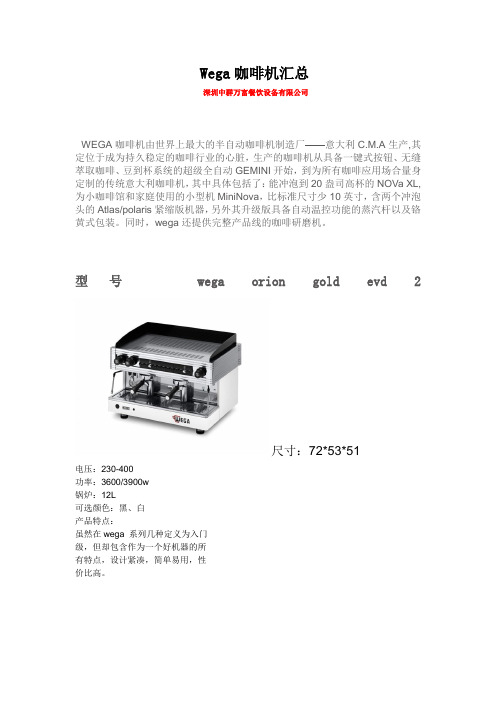
Wega咖啡机汇总深圳中群万富餐饮设备有限公司WEGA咖啡机由世界上最大的半自动咖啡机制造厂——意大利C.M.A生产,其定位于成为持久稳定的咖啡行业的心脏,生产的咖啡机从具备一键式按钮、无缝萃取咖啡、豆到杯系统的超级全自动GEMINI开始,到为所有咖啡应用场合量身定制的传统意大利咖啡机,其中具体包括了:能冲泡到20盎司高杯的NOVa XL,为小咖啡馆和家庭使用的小型机MiniNova,比标准尺寸少10英寸,含两个冲泡头的Atlas/polaris紧缩版机器,另外其升级版具备自动温控功能的蒸汽杆以及铬黄式包装。
同时,wega还提供完整产品线的咖啡研磨机。
型号wega orion gold evd 2尺寸:72*53*51电压:230-400功率:3600/3900w锅炉:12L可选颜色:黑、白产品特点:虽然在wega 系列几种定义为入门级,但却包含作为一个好机器的所有特点,设计紧凑,简单易用,性价比高。
型号new ATLAS EVD寸:740*570*520mm电压/功率:230V-380V/3700w锅炉大小:16L颜色:红、黑、沙色产品特点:产品特点——全铜12L锅炉+全金属架结构,热稳定性好,经久耐用;——.独特内置水冷电机驱动平衡式离心泵,提供标准和稳定压力;——2个A61热循环式冲泡头,保证冲泡前冲泡头和手柄恒定温度——跳针开关预浸泡功能,实现完美萃取——电子(四组程序设定杯量)+手动按键,提供最大便利和双重保险——人体工学操作手柄,简单易用——双蒸汽杆,提供强劲蒸汽——自动设定水位标准、——时尚LED灯,可在全黑酒吧工作型号wega concept尺寸:80*60*59电压:230-400v总功率:4400w冲泡头功率:2*150w冲泡头水箱功率:2*1000w蒸汽锅炉功率:3000w蒸汽锅炉容量:8L煮咖啡锅炉容量:2*1.2突出优势:1、SLS:自主学习软件系统;2、MBT:多锅炉系统3、LEC:绿色节能(工作状态节约30%,休息状态节约47.6%)4、HSB:高安全性主要性能:1、液晶显示,可做多种程序设定2、双蒸汽杆,可选配自动打奶沫系统3、支持高杯4、每组冲泡头可设定6 组程序杯型号polaris evd尺寸 76*57*52 电压 220V-380V 功率 2600/3400W产品特点:——全不锈钢架构,时尚豪华机身——E61 热补偿式冲泡头,具备预浸润功能——水冷式可调整回旋式水泵——双蒸汽杆+1 个热水出口——双表显示+透明水位视窗其中:——电控版可设定热水量以及含四组可程序设定咖啡杯量——可选配显示屏,设定时间、日期,出杯量计数,电源自动开和关,以及软水器再生自动报警等功能型号vela型号 sphere来自深圳中群万富餐饮设备有限公司。
蒸汽机器人-冷却螺纹液化机和水 水热泵RTWF(R134a R513A)370-1860kW RTW

Water-Cooled Screw Chillers and Water/Water Heat PumpsModel RTWF (R134a / R513A)370 - 1860 kWModel RTWF G (R1234ze)355 - 1420 kWModel RTHF (R134a)1140 - 3670 kWModel RTHF G (R1234ze)750 - 2670 kWSEER up to 10.12 Water-Cooled Screw Chillers and Water/Water Heat PumpsThere is world-wide demand for increasingly efficient products to reduce energy and resource consumption. As part of our sustainable product policy, Trane has always been committed to respecting the environment by reducing energy consumption through the delivery of high performing and efficient products and systems.Trane XStream™ series provides reliable temperature control in the most demanding applications. Exceptional efficiency keeps your operating costs and environmental impact low. Smart and easy to use controls ensure you get the best out of your system day after day, year after year.Trane XStream are available with a choice of 3 refrigerants: R134a, R513A or R1234ze which has a GWP value of less than one to exceed current F-Gas legislation requirements and help customers reduce carbon dioxide (CO 2) emissions and achieve extreme part load and full load efficiencies.Trane XStream™Water-Cooled Chillers and Water/Water Heat PumpsXStream chillers and heat pumps are ideal for• Cooling and heating applications• High and medium temperature industrial process applicationsOffice buildings Healthcare Data Centers Automotive industryPharmaceuticalindustry Food and beverage industryHospitality industryDistrict CoolingDistrict Heating3• Extra High Efficiency (XE)• High Seasonal Efficiency (HSE) with integrated variable speed: Trane Adaptive Frequency™ Drive• Extra High Seasonal Efficiency (XSE) with Variable Vi compressor and integrated variable speed: Trane Adaptive Frequency™ Drive.Trane exceptional reliabilityWith equipment as critical as an HVAC system or industrial process, quality is non-negotiable. At Trane we manufacture and design the core components and put our systems through extremely rigorous performance and reliability tests. All Trane units are given a complete test before leaving our factory. As a result, Trane customers benefit from proven, industry-leading reliability and durability.Extreme versatilityXStream range that will satisfy your needs.By selecting the appropriate efficiency version, you can minimize your Total Cost of Ownership.For even greater system efficiency, Trane XStream units are fully compatible with Variable Primary Flow (VPF) applications and Series chiller arrangements.Range DescriptionA model for every needThe fluorinated refrigerants phase-down, as defined in the new EU F-Gas Regulation, is a step-by-step approach where the quantities of HFCs expressedin CO2equivalent that are placed on the market are gradually reduced. As a result of the phase-down, HFC consumption will be reduced by 79% by 2030.This is an unprecedented reduction and meansthat industry and users need to make, over time, the transition to refrigerants with a lower global warming potential.Trane, recognized as a leading innovator in the HVAC industry, introduces this new, next generation, lower GWP refrigerant in Sintesis and other products to be front running in the marketplace and to support your strong sustainability objectives.The Future of F-Gases4 Water-Cooled Screw Chillers and Water/Water Heat Pumps5What is GWP?GWP is the global warming impact relative to the impact of the same quantity of carbon dioxide over a 100 year period.What is ODP?Ozone depletion potential of a chemical is the amount of degradation to the ozone layer it can cause.XStream™ chillers and heat pumps with low GWP refrigerants are part of the EcoWise™ portfolio of products that are designed to lower their environmental impact with next-generation, low global warming potential (GWP) refrigerants and high-efficiency operation.New R1234zeOzone depletion potential = 0Low global warming potential (GWP<1)R410A 1924R407C 1774R134a 1300R513A 572R1233zd 1R1234ze<1An environmentally sustainable solution6 Water-Cooled Screw Chillers and Water/Water Heat PumpsXStream chillersThe smart choice for cooling applicationsBecause chillers rarely operate at design conditions, Trane developed the XStream range to achieve industry-leading part load efficiencies without compromising the environment.Unique and innovative features• Multiple compressor design allows outstanding part load efficiencies by switching compressors off while utilizing the entire heat exchanging surface for the remaining compressor(s)• XStream chillers and heat pumps take advantage of crossflow serial heat exchanger design to reduce compressor workload under all operating conditions.This layout provides the opportunity for• Lower chilled water design temperature with larger ΔT • Reduced design flow• Installation and operational cost savings by fewer installed pumps and valves, reduced pipe diameters and chiller downsizing• Maximized system efficiency• Continuous temperatures allow better stability of controlsBy combining series configuration with Variable Primary Flow (VPF) it is possible to further increase system efficiency.Overall efficiency can be further improved by using an alternative chiller lay-out to the conventional parallel-piped configuration. For example, chillers can be piped in series, on the evaporator side, on the condenser side or both.2.3 MW2.0 MW31° C10° C2.1 MW37° CVariable Primary Flow (VPF) capabilitiesVPF systems provide building owners with multiple cost savings derived directly from pump operation.The XStream series is designed to make VPF easy to use.• The evaporator on the XStream series can run safely with up to 50% water flow reduction• The microprocessor and capacity control algorithms are designed to handle a maximum of 10% changein water flow rate per minute in order to maintain ±0.3°C temperature control leaving the evaporator.• For applications in which system energy savings are the priority and tight temperature control is classified as +/- 1.1°C, up to 30% change in flow per minute is possible.• With the help of a TRANE software analysis tool, you can determine whether the anticipated energy savings justify the use of VPF in a particular application.Variable Vi capabilities on RTWF XSE and RTHF XSEWe take part load efficiency one step further by using the latest Trane screw compressor with Variable Volume Index (Variable Vi) that allows the chiller to operate at the most appropriate pressure ratio to reach remarkable efficiency levels. Variable Vi increases part load efficiency (SEER) by 10% vs. the equivalent model at Fixed Vi. RTHF XSE can reach SEER’s as high as 10.1.XStream heat pumpsIdeal for heating applicationsThe market for heat pumps in Europe has grown substantially year over year as the advantages of heat pumps are proven. Trane introduces new technologies creating sustainable solutions using renewable energy.Unique and innovative featuresthe needs of geothermal and district heating applications:• Compressors specially designed for high temperature applications• Large capacities up to 2020 kW (at Eurovent Air Conditioning heating conditions)• High condensing water temperatures of up to 85°C (RTWF G) allowing operation as a high temperature heat pump or a high condensing temperature cooling system.• High performance up to 4.8 COP (at Eurovent Air Conditioning heating conditions)• Operates down to 10% part load requirements.High condensing watertemperatures of upto 85°C.8 Water-Cooled Screw Chillers and Water/Water Heat Pumps9Peace of mind while saving energy costsauxiliary heating sources to treat Legionella bacteria can now be scaled back or totally eliminated.Geothermal applicationsThe technologies built into Trane’s XStream series heat pumps make them ideally suited to geothermalapplications.Trane air handling unitsCentral XStream units to produce hot/cold water for heating and coolingGeothermal loop10 Water-Cooled Screw Chillers and Water/Water Heat PumpsConnectivity• Full interoperability via SmartCom interface Lontalk®, BACnet® and Modbus• Full remote control capability via Trane BMSor Chiller Plant ControlsTrane industry-leading compressor*• Direct drive, twin screw helical rotary design • Variable Vi on RTWF and RTHF XSE version • Infinite capacity modulation• Semi hermetic design eliminating shaft seals • Trane unequaled reliability1Trane combined smart control and interface*• Leading TD7 touch screen with 7” color display • Clear presentation of critical information• Monitor settings, data trending, reports and alarms • Simple, intuitive navigation• Effective operation, monitoring and management • Durable construction for both indoor and outdoor use3Heat exchangers*• Single pass• Counter flow configuration4Two different refrigerant alternatives on RTWF• R134a• R1234ze with GWP<1Model RTHF* Trane Proprietary TechnologyFeaturesInnovative solutions to your needs134211Trane patented Compact - High performance - Integrated design - Low charge (CHIL) flooded evaporator*• Reduced refrigerant volume • Increased efficiency • Reduced carbon footprintTrane controller*• New generation Trane control platform for chillers• Advanced algorithms for the most challenging conditions• Maintains efficient and reliable operationAdaptive Frequency™ Drive on HSE and XSE version*• Improved efficiency under part load conditions • Improved capacity modulation2134212 Water-Cooled Screw Chillers and Water/Water Heat PumpsRefrigerantR134a / R513AR1234ze R134a R1234ze Condenser leaving water temperature (Min/Max)(°C)+10 / +68+10 / +80 (1) +10 / +85 (2)+10 / +50+10 / +50Evaporator leaving water temperature (Min/Max)(°C)-12 / +20-12 / +27-12 / +20-12 / +20Power Supply(V/Ph/Hz)400/3/50General Data for cooling performances(1) Evaporator 12/7°C and 0.0 m²K/kW, and condenser at 30/35°C and 0.0 m²K/kW (2) Net performances calculated as per EN 14511-2013.(3) ηs,c / SEER as defined in Directive 2009/125/EC of the European Parliament and of the Council with regard to Ecodesign requirements for Comfort Chillers with 2000 kW maximum capacity - COMMISSION REGULATION (EU) N° 2016/2281 of 20 December 2016(1) Sizes 095 to 165(2) Sizes 220 to 420RTWF SE (Standard Efficiency)Net cooling capacity (1) (2)(kW)368417487544591646702777845939983104311121250139715371676Net EER (1) (2)5.18 5.11 5.02 5.15 5.2 5.14 4.98 5.03 5.01 4.88 4.86 4.88 4.88 4.83 4.9 4.88 4.89Eurovent Energy class - Cooling A A B A A A B B B B B B B B B B B SEER (3)6.836.85 6.90 6.937.037.037.00 6.95 6.88 6.90 6.88 6.78 6.95 6.907.387.437.33Space cooling efficiency ηs.c (3)(%)270271273274278278277275272273272268275273292294290Number of refrigerant circuits 11111111122222222Number of compressors 22222222233333444Sound Power Level (dB(A))999996969699101101101100100101101101102102102Length (mm)30803080308030803080316031603160316047544754478447844784477447744774Width (mm)11901190119011901190122512501250125017271727172717271727182318231823Height(mm)19001900190019351935193520352035208020322032203220322032213521352135Operating Weight(kg)26222641304831943215345637833884398852765273545655115574694570257109RTWF HE (High Efficiency)General specificationsNet cooling capacity (1) (2)(kW)3714294995526006587167878549571003106611341267142315631706Net EER (1) (2)5.33 5.35 5.21 5.36 5.43 5.32 5.18 5.21 5.12 5.26 5.26 5.24 5.24 5.22 5.29 5.23 5.23Eurovent Energy class - Cooling A A A A A A A A A A A A A A A A A SEER (3)6.937.037.107.137.207.237.137.03 6.937.337.307.157.287.207.757.687.53Space cooling efficiency ηs.c (3)(%)274278281282285286282278274290289283288285307304298Number of refrigerant circuits 11111111122222222Number of compressors 22222222233333444Sound Power Level (dB(A))999996969699101101101100100101101101102102102Length (mm)30803080308031603160316031603160316047544754478447844784477447744774Width (mm)11901190119012151215125012501250125017271727172717271727182318231823Height(mm)19001935193520552055208020802080208020322032203220322032213521352135Operating Weight(kg)2696281931963490356437903969413941395687568358865950612374467571769413(1) Evaporator 12/7°C and 0.0 m²K/kW, and condenser at 30/35°C and 0.0 m²K/kW(2) Net performances calculated as per EN 14511-2013.(3) ηs,c / SEER as defined in Directive 2009/125/EC of the European Parliament and of the Council with regard to Ecodesign requirements for Comfort Chillers with 2000 kW maximum capacity - COMMISSION REGULATION (EU) N° 2016/2281 of 20 December 2016100 120 140 150 170 180 190 210 230 250 275 290 310 330 370 410 450 490 515 Net cooling capacity (1) (2)(kW)37443250155560365871678284993095910051066113412581423156316971859Net EER (1) (2)5.24 5.28 5.18 5.32 5.4 5.21 5.09 5.1 5.02 4.85 5.17 5.17 5.12 5.12 5.1 5.19 5.15 5.14 4.95Eurovent Energy class - Cooling A A A A A A A A B B A A A A A A A A B SEER (3)6.957.157.207.257.337.337.207.107.187.137.337.357.537.487.487.587.407.387.33Space cooling efficiency ηs.c (3)(%)275283285287290290285281284282290291298296296300293292290Number of refrigerant circuits 1111111111222222222Number of compressors 2222222222333334444Sound Power Level (dB(A))999996969699101101101103100100101101101102102102107Length (mm)3080308030803160316031603160316031603160475447544784478447844774477447744774Width (mm)1260126012601285128513801380138013801380172717271727172717271823182318231823Height(mm)1900193519352055205520802080208020802080203220322032203220322135213521352135Operating Weight(kg)2796291932963590367038904069423942394239586258586100616463377660778579087907RTWF HSE (High Seasonal Efficiency)RTWF XSE (Extra High Seasonal Efficiency)Net cooling capacity (1) (2)(kW)40764682210581314Net EER (1) (2)5.54 5.27 5.66 5.48 5.53Eurovent Energy class - Cooling A A A A A SEER (3)8.418.498.738.748.91Space cooling efficiency ηs.c (3)(%)333337346346353Number of refrigerant circuits 11222Number of compressors 11222Sound Power Level (dB(A))9496979899Length (mm)26832683458645864586Width (mm)11521152119011901190Height(mm)19952045211021302130Net cooling capacity (1) (2)(kW)1155.51268.51467.01583.71777.31897.32109.12248.92509.42644.42824.83007.9Net EER (1) (2)5.97 5.84 5.83 5.81 5.76 5.776.21 6.03 6.15 6.02 5.88 5.77Eurovent Energy class - Cooling A A A A A A A A A A A A SEER (3)7.537.407.357.307.437.538.037.888.007.607.557.35Space cooling efficiency ηs.c (3)(%)298993291289294298318312317301299291Number of refrigerant circuits 222222222222Number of compressors 222222222222Sound Power Level (dB(A))979798989999102103103103103103Length (mm)458645864586458645864586552155215521552155215521Width (mm)184018401840184018401840208820882088208820882088Height(mm)239523952395239523952395245724572457245724572457Operating Weight(kg)73507450745085908590963096801338013380133801349013610RTHF XE (Extra Efficiency)14 Water-Cooled Screw Chillers and Water/Water Heat PumpsRTHF HSE (High Seasonal Efficiency)330360 410 460 500 540 590 640 600 650 700 750 800 840 850 900 950 Net cooling capacity (1) (2)(kW)1153.21267.01466.01581.11771.71890.72083.42270.62104.02238.92499.22635.32815.02995.12995.13219.93445.13671.7Net EER (1) (2)5.81 5.71 5.72 5.69 5.66 5.65 5.48 5.306.09 5.90 6.03 5.91 5.78 5.66 5.64 5.33 5.07 4.84Eurovent Energy class - Cooling A A A A A A A A A A A A A A A A A B SEER (3)8.738.738.708.838.889.058.888.739.639.439.459.359.289.139.108.958.838.68Space cooling efficiency ηs.c (3)(%)346346345350352359352346382374375371368362361355350344Number of refrigerant circuits 222222222222222222Number of compressors 222222222222222222Sound Power Level (dB(A))979798989999102104102103103103103103103103107109Length (mm)458645864586458645864586458645865521552155215521552155215521552155215521Width (mm)194019401940194019401940194019402088208820882088208820882305230523052305Height(mm)239523952395239523952395239523952457245724572457245724572457245724572457Operating Weight(kg)7520762088208820992099709970997013440137401374013740138501397014570145701457014570RTWF SE (Standard Efficiency)Net cooling capacity (1) (2)(kW)485.0542.0589.0643.0700.0774.0841.0Net EER (1) (2)4.82 4.94 4.98 4.93 4.77 4.81 4.79Eurovent Energy class - Cooling B B B B B B B SEER (3)6.556.58 6.58 6.75 6.73 6.65 6.55Space cooling efficiency ηs.c (3)(%)259260260267266263259Number of refrigerant circuits 1111111Number of compressors 2222222Sound Power Level (dB(A))96969699101101101Length (mm)3080308030803160316031603160Width (mm)1190119011901225125012501250Height(mm)1900193519351935203520352080Operating Weight(kg)3048319432153456378338843988(1) Evaporator 12/7°C and 0.0 m²K/kW, and condenser at 30/35°C and 0.0 m²K/kW (2) Net performances calculated as per EN 14511-2013.(3) ηs,c / SEER as defined in Directive 2009/125/EC of the European Parliament and of the Council with regard to Ecodesign requirements for Comfort Chillers with 2000 kW maximum capacity - COMMISSION REGULATION (EU) N° 2016/2281 of 20 December 2016RTHF XSE (Extra High Seasonal Efficiency)Net cooling capacity (1) (2)(kW)2972318834073633Net EER (1) (2)5,555,275,064,79Eurovent Energy class - Cooling A A A B SEER (3)10,139,889,709,50Space cooling efficiency ηs.c (3)(%)402392385377Number of refrigerant circuits 2222Number of compressors 2222Sound Power Level (dB(A))103109110111Length (mm)5521552155215521Width (mm)2305230523052305Height(mm)2457245724572457Operating weight(kg)1436014470145901459015(1) Evaporator 12/7°C and 0.0 m²K/kW, and condenser at 30/35°C and 0.0 m²K/kW(2) Net performances calculated as per EN 14511-2013.(3) ηs,c / SEER as defined in Directive 2009/125/EC of the European Parliament and of the Council with regard to Ecodesign requirements for Comfort Chillers with 2000 kW maximum capacity - COMMISSION REGULATION (EU) N° 2016/2281 of 20 December 2016RTWF HE (High Efficiency)Net cooling capacity (1) (2)(kW)498.0550.0598.0656.0713.0783.0850.0Net EER (1) (2)5.06 5.12 5.19 5.09 4.95 4.97 4.88Eurovent Energy class - Cooling A A A A B B B SEER (3)6.836.85 6.90 6.90 6.80 6.68 6.60Space cooling efficiency ηs.c (3)(%)270271273273269264261Number of refrigerant circuits 1111111Number of compressors 2222222Sound Power Level (dB(A))96969699101101101Length (mm)3080316031603160316031603160Width (mm)1190121512151250125012501250Height(mm)1935205520552080208020802080Operating Weight(kg)3196349035643790396941394139RTWF HE G (High Efficiency)Net cooling capacity (1) (2)(kW)356391461494545595747.0802.0893.01010.01101.01206.0Net EER (1) (2)4.55 4.56 4.7 4.75 4.78 4.92 4.88 4.9 4.865.03 4.97 4.99Eurovent Energy class - Cooling C C B B B B B B B B B B SEER (3)5.936.00 6.45 6.48 6.68 6.80 6.33 6.53 6.38 6.63 6.75 6.93Space cooling efficiency ηs.c (3)(%)234237255256264269250258252262267274Number of refrigerant circuits 111111222222Number of compressors 222222333444Sound Power Level (dB(A))969695939393969696979797Length (mm)308030803160316031603160478447844784478447844784Width (mm)119011901225122512501250172717271727182318231823Height(mm)193519351935193520352080203220322032213521352135Operating Weight(kg)317631763271330736223796551756105804700771297353RTWF SE G (Standard Efficiency)Net cooling capacity (1) (2)(kW)34337444948052458273678987799610841187Net EER (1) (2)4.34 4.32 4.5 4.53 4.54 4.67 4.67 4.64 4.59 4.75 4.66 4.68Eurovent Energy class - Cooling C C C C C B B C C B B B SEER (3)5.785.856.33 6.33 6.50 6.65 6.00 6.08 5.98 6.63 6.65 6.65Space cooling efficiency ηs.c (3)(%)228231250250257263237240236262263267Number of refrigerant circuits 111111222222Number of compressors 222222333444Sound Power Level (dB(A))969695939393969696979797Length (mm)308030803160316031603160478447844784478447844784Width (mm)119011901225122512501250172717271727182318231823Height(mm)190019001935193520352080203220322032213521352135Operating Weight(kg)29592959312831643452357951355228537365546676688516 Water-Cooled Screw Chillers and Water/Water Heat Pumps(1) Evaporator 12/7°C and 0.0 m²K/kW, and condenser at 30/35°C and 0.0 m²K/kW(2) Net performances calculated as per EN 14511-2013.(3) ηs,c / SEER as defined in Directive 2009/125/EC of the European Parliament and of the Council with regard to Ecodesign requirements for Comfort Chillers with 2000 kW maximum capacity - COMMISSION REGULATION (EU) N° 2016/2281 of 20 December 2016RTHF XE G (Extra Efficiency)Net cooling capacity (1) (2)(kW)853.0943.01087.01170.01313.01400.01579.01685.01882.01964.02070.02178.0Net EER (1) (2)5.79 5.77 5.74 5.71 5.67 5.676.2 6.02 6.27 6.1 5.91 5.77Eurovent Energy class - Cooling A A A A A A A A A A A A SEER (3)7.257.137.157.257.067.177.757.237.767.547.547.32Space cooling efficiency ηs.c (3)(%)287282283287279284307286308298299293Number of refrigerant circuits 222222222222Number of compressors 222222222222Sound Power Level (dB(A))979798989898102103103103103103Length (mm)458645864586458645864586552155215521552155215521Width (mm)184018401840184018401840208820882088208820882088Height(mm)239523952395239523952395245724572457245724572457Operating Weight(kg)750875608745874596799679128811335613356133561345613566RTHF HSE G (High Seasonal Efficiency)Net cooling capacity (1) (2)(kW)928.01016.01104.01212.01396.01523.01657.01810.01964.02109.02254.0241325852755Net EER (1) (2)5.54 5.32 5.15 4.88 5.21 5.27 5.1 4.776.12 5.97 5.82 5.60 5.36 5.15Eurovent Energy class - Cooling A A A B A A A B A A A A A A SEER (3)7.387.367.297.237.998.087.987.878.158.118.088.298.108.02Space cooling efficiency ηs.c (3)(%)292291289286316320316312323321320329321318Number of refrigerant circuits 22222222222222Number of compressors 22222222222222Sound Power Level (dB(A))97100102105102100102106103103103106107109Length (mm)45864586458645864586458645864586552155215521552155215521Width (mm)19401940194019401940194019401940208820882088208820882088Height(mm)23952395239523952395239523952395245724572457245724572457Operating Weight(kg)77307720772077208960995999599959136761381613926139261392613926RTWF HSE G (High Seasonal Efficiency)095105 125 135 155 165 185 205 220 240 280 300 320 360 380 420 Net cooling capacity (1) (2)(kW)356392461495548598646695747.0803.0898.01010.01101.01211.01308.01417.0Net EER (1) (2)4.54 4.53 4.63 4.69 4.73 4.87 4.74 4.6 4.85 4.90 4.845.01 4.96 4.98 4.80 4.71Eurovent Energy class - Cooling C C C B B B B B B B B B B B B B SEER (3)5.755.63 5.93 5.986.03 6.15 6.13 6.08 6.35 6.35 6.25 6.43 6.55 6.70 6.63 6.55Space cooling efficiency ηs.c (3)(%)227222234236238243242240251251247254259265262259Number of refrigerant circuits 1111111122222222Number of compressors 2222222233344444Sound Power Level (dB(A))969695939393959796969697979799101Length (mm)3080308031603160316031603160316047844784478447844784478447844784Width (mm)1260126013501350138013801380138017271727172718231823182318231823Height(mm)1935193519351935203520802080208020322032203221352135213521352135Operating Weight(kg)327632763371340737223896402540255731582460187221734375677567765317General Data for heating performances(1) At 40/45°C Entering/Leaving Condenser and 10/7°C Entering/Leaving Evaporator (2) Net performances calculated as per EN 14511-2013.(3) ηs,h / SCOP as defined in Directive 2009/125/EC of the European Parliament and of the Council with regard to Ecodesign requirements for space heaters with 400 kW maximum rated capacity - COMMISSION REGULATION (EU) N° 813/2013/EU of 2 August 2013(4) At 47/55°C Entering/Leaving Condenser and 10/7°C Entering/Leaving EvaporatorRTWF SE (Standard Efficiency)Net Heating Capacity (2)(kW)389.5453.9523.8584.1636.0695.2758.1826.1889.61035.41085.91149.31215.31346.41537.41669.71800.7Net COP (2)4.194.224.334.394.394.354.314.394.424.404.374.384.404.424.394.424.46Net Heating Capacity (2)(kW)372.9438.1492.8567.5599.5655.6716.2780.1840.5975.81023.91083.11146.01270.61449.01574.71699.0Net COP (2) 3.56 3.62 3.58 3.78 3.67 3.64 3.61 3.67 3.68 3.67 3.66 3.67 3.69 3.71 3.68 3.71 3.74SCOP(4)4.59 4.83 3.835.08 3.90 3.83 4.73 3.93 5.98 5.13 5.10 5.05 5.13 5.15 5.23 5.35 5.35Space Heating efficiency ηs.h (3)(%)176185145195148145181149195197196194197198201206206RTWF HE (High Efficiency)Net Heating Capacity (2)(kW)391.1463.3533.8589.9641.9695.6750.2822.2892.61045.61097.11164.31228.01352.91551.01683.21817.0Net COP (2)4.274.384.464.544.564.614.664.684.734.614.594.594.624.644.604.634.67Net Heating Capacity (2)(kW)369.2442.9512.1564.4610.9657.3711.3778.2845.1986.21035.31098.31158.81276.51462.81588.71715.1Net COP (2) 3.55 3.69 3.75 3.81 3.82 3.82 3.87 3.88 3.93 3.82 3.81 3.82 3.84 3.86 3.83 3.85 3.88SCOP(4)4.63 4.885.03 5.08 5.10 4.03 5.28 4.05 5.38 5.20 5.20 5.15 5.20 5.20 5.28 5.38 5.38Space Heating efficiency ηs.h (3)(%)17718719319519615320315420720020019820020020320720718 Water-Cooled Screw Chillers and Water/Water Heat Pumps(1) At 40/45°C Entering/Leaving Condenser and 10/7°C Entering/Leaving Evaporator (2) Net performances calculated as per EN 14511-2013.(3) ηs,h / SCOP as defined in Directive 2009/125/EC of the European Parliament and of the Council with regard to Ecodesign requirements for space heaters with 400 kW maximum rated capacity - COMMISSION REGULATION (EU) N° 813/2013/EU of 2 August 2013(4) At 47/55°C Entering/Leaving Condenser and 10/7°C Entering/Leaving EvaporatorRTWF SE (Standard Efficiency)Net Heating Capacity (2)(kW)386.2449.9513.1575.3628.5688.3752.2828.9901.2Net COP (2)4.054.084.184.244.254.224.194.264.27Net Heating Capacity (2)(kW)366.5430.2492.0555.6606.1657.7726.4749.9772.5Net COP (2) 3.41 3.47 3.53 3.63 3.64 3.58 3.60 3.60 3.58SCOP(4)4.70 4.70 4.80 4.905.00 4.90 4.90 5.00 5.00Space Heating efficiency ηs.h (4)(%)180180184188192188188192192RTWF HE (High Efficiency)Net Heating Capacity (2)(kW)387.7459.4523.3580.8634.1688.1742.9813.9883.6Net COP (2)4.134.234.304.384.404.464.504.524.57Net Heating Capacity (2)(kW)362.2435.0498.8552.0598.8655.3712.9769.9839.1Net COP (2) 3.39 3.53 3.59 3.65 3.65 3.74 3.81 3.76 3.83SCOP(4)4.43 4.53 4.65 4.70 4.73 4.95 4.95 4.985.03Space Heating efficiency ηs.h (4)(%)169173178180181190190191193RTWF HSE (High Seasonal Efficiency)100 120 140 150 170 180 190 210 230 250 275 290 310 330 370 410 450 490 515 Net Heating Capacity (2)(kW)396.9465.9534.2592.2644.2692.3746.9818.3888.7966.11048.61102.11169.81233.41376.51556.61688.81841.02019.0Net COP (2)4.224.324.434.504.524.544.584.604.654.544.554.534.524.544.524.544.574.584.49Net Heating Capacity (2)(kW)375.5446.2512.8567.3613.8653.8707.8774.0841.0917.5990.31041.51105.21165.71300.91469.81595.81739.81912.3Net COP (2) 3.50 3.63 3.73 3.78 3.79 3.73 3.78 3.79 3.85 3.78 3.76 3.76 3.74 3.77 3.76 3.77 3.80 3.81 3.76SCOP(4)4.58 4.755.03 5.00 5.03 3.90 3.90 3.90 3.98 3.90 5.25 5.23 5.25 5.25 5.25 5.30 5.35 5.38 5.30Space Heating efficiency ηs.h (4)(%)175182193192193148148148151148202201202202202204206207204RTWF XSE (Extra High Seasonal Efficiency)Net Heating Capacity (2)(kW)45271490411731429Net COP (2)5,044,865,094,975,08Net Heating Capacity (2)(kW)43369486711281394Net COP (2)4,163,974,214,094,13SCOP(4)5,855,895,875,936,10Space Heating efficiency ηs.h (4)(%)226228227229236。
飞龙 wi
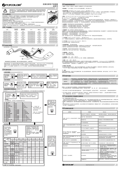
持续电流(散热良好)瞬间电流(散热良好)BEC尺寸(供参考)重量(供参考)20A 30A 40A 60A 30A 40A 55A 80A 锂电池型号79g 35g 36g 76g 49x23.5x13.5mm 65.5x34x21mm● 反推功能,支持飞行过程中切换电机正反向,达到减速目的(WinDragon wifi 80-130A 支持此功能)。
2-4S 2-4S 2-6S 2-6S 8.4V/7.4V/6V/5V ,5A 80A 100A 119g 2-6S 100A 120A 125g 2-6S 130A150A130g82.5x39.5x23.5mm2-6S航模无刷电子调速器WinDragon wifi 130AWinDragon wifi 100A WinDragon wifi 80A WinDragon wifi 60A WinDragon wifi 30A WinDragon wifi 40A WinDragon wifi 20A 8.4V/7.4V/6V/5V ,5A 8.4V/7.4V/6V/5V ,5A 8.4V/7.4V/6V/5V,5A8.4V/7.4V/6V/5V ,5A 82.5x39.5x23.5mm 82.5x39.5x23.5mm 65.5x34x21mm 49x23.5x13.5mm 02 产品规格04 操作说明1.正常工作模式2.油门行程设定3.通过遥控器进行参数编程设定推荐使用Flycolor Wi-Fi Trans 通过Flycolor App 进行参数编程设定。
另外可通过编程卡进行参数编程设定1. 刹车: [1] 无刹车 [2]软刹车 [3]重刹车 [4]很重刹车 (出厂默认值为无刹车)2.电池类型: [1]LiPo(锂电) [2] NiCb/NiMh(镍氢/镍隔) (默认值为Li Po )3.低压保护阈值:低/中/高 [1] 2.8V [2]3.0V [3]3.2V ;默认值为中(3.0V)对于Ni-xx电池组:低/中/高中止电压是电池组初始电压值的50%/65%/75%对于Li-xx电池组:可自动计算电池数量,除了确定电池 类型外无需用户设置。
AWW 机组简介
CAC R&D / Nov 2010
Page 13
机组安装
安装必须注意事项
1 要安全:电,火,水,防冻,防漏,防污染,其他特别安全措施。 2 要专业规范:资质,专业,国标和行业规范。 3 要经济和方便等:可靠经济性,维修保养。 4 机组安装基础须牢固,平整,必要时找平。 5 机组地脚安装须做减震措施。 6 机组禁密集安装,机组间距至少要有0.6m。
否则可能发生触电事故。
4 电源容量必须满足机组要求,要考虑电压降因素,额定电压±10%以内, 额定电源频率±2%以内。
5 电气接线时必须断开电源,禁止带电操作。 6 按电气线路图进行接线,电源线及控制线必须使用GB5013规定的245IEC57型
或同等以上的电线。
7 机组的连接线需用压线板固定,各接线间应拉开距离,并保证外部张力不对 端子板产生过度的拉力。同时还应检查机组内部配线是否有脱落松动。
Airwell
AirGwroeulpl
Group
AWW series 2010.11
Jin Jianming
CAC R&D / Nov 2010
Page 1
AWW系列 整体冷热水水源热泵机组
Airwell Group
CAC R&D / Nov 2010
Page 2
AWW 命名规则
Airwell Group
同时还应检查机组内部配线是否有脱落松动。 8为保护人员安全,机组壳体应有可靠的接地保护装置,确保接地良好(接地电阻不得超过4欧姆)。 9接地线不要连接在煤气管、水管、电话或避雷针的线路上及装有漏电保护器的其它产品接地线路上。 10主机连接电缆线、电源线应与电视机、电脑等家用电器保持至少1米距离,以免相互干扰。 11 强电和弱电分开。
Parker Hyperchill 工业冷水冷却机系列说明说明书
|Parker Hyperchill water chillers celebrate a presence of over 30 years in the industrial chiller market. This experience has led to a range which not only offers all the advantages typically offered by a quality water chiller, but also adds significant benefits for the industrial user. As such Hyperchill combines advanced design solutions, such as ener-gy saving scroll compressors and a sophisticated micro-processor, with unique features to meet the specific needs of industrial users: these include Hyperchill’s extreme flexibility towards the varying working conditions typically found in industry. The standard models are augmented by a wide range of options and accessories, which together ensure Hyperchill is the perfect solution to each and every industrial application. Hyperchill maxi-mizes productivity and minimizes costs, as well as easing conformity to regulations on water quality. Hyperchill is the perfect solution to industrial chilled water needs.FOCUSED ONFLEXIBILE SOLUTIONSApplications• Food (beverage, confectionery, chocolate,processing, storage)• Plastics (injection, blow molding, extrusion,film extrusion, thermoforming)• Lasers (welding, profiling, cutting, optics, medical, marking, aesthetics)• Printing and Graphics (manufacture, printing,cardboard, labels, plastic film)• Chemical (petrochemical, paints, solvents, temperature control)• Medical (imaging and oncology)• Mechanical (welding, cutting, profiling,polishing, rolling, grinding)• Other (wood, ceramics, gold & silver, biogas,pharmaceutical, compressed air, textile)The use of cold water is very common in industry. The motives are obvious: cold water improves productivity, secures industrial processes, and reduces costs. There are several methods of creating cold water, but water chillers are increasingly becoming the preferred solution. This can be attributed to the fact that chillers always supply the exact water temperature requested, even with differing ambient conditions and differing load requests, thus ensuring optimum efficiency. Water has furthermore become a very precious, and costly, natural resource. Chillers, by operating in a closed circuit, continuously reutilize the same water, and thereby avoid unwanted water waste. In addition, a number of directives have recently emerged to safeguard the quality of the water being utilized (for health reasons) as well as to restrict the discharge of impure water (to protect the envi-ronment); closed circuit chiller operation greatly simplifies conformance to these regulations. The needs of industry are changing, and a water chiller increasingly satisfies these needs.• Increases productivity, reduces costs• Optimizes industrial applications• Adaptable to individual customer needs• Accepts wide range of water temperaturesand fluctuating water flowsEasy to UseHyperchill is an all-in-one solution, with all components packaged inside. Compact dimensions and a low weight make it simple to position; all models can be installed outdoors.Maintenance is facilitated by removable front and side panels, and a condenser section which is isolated from the rest of the chiller.Hyperchill can be used in pressurized closed circuits, facilitating Economical & Environmentally FriendlyHyperchill standardly uses environmentally friendly refrigerant R407C on all models. R407C is characterized by a very high efficiency, providing lower power consumption.Fitted scroll compressors offer energy savings of around 20%. Multiple compressors (from PCW210) ensure significant energy savings at partial loads.Fail-Safe OperationHyperchill operates continuously in all conditions and with all appli-cations. Multiple compressors and twin independent refrigeration circuits (from PCW210) with automatic rotation offer increased peace of mind, as do an extensive list of safety devices.The oversized condensers with cleanable pre-filters ensure that Hyperchill operates in extreme ambients.Features & BenefitsCleanable Condenser Pre-filterA condenser pre-filter (standard) improves chiller performance and reduces maintenance.Scroll CompressorsHyperchill features advanced scroll compressors. These offer significantly lower power consumption and a reduced refrigerant charge . The unique tech-nology offers extreme reliability and renders the compressor near indestructible . Scroll compressors are also very user friendly , as they are extremely quiet and ensure the chiller requires no pre-heating . Furthermore, scroll compressors feature 50% fewer moving parts and emit lower vibration levels, thus increasing the chiller’s longevity ./igfgIntegral PumpAs a standard feature, a pump is installed within the chiller itself. Twin pumps, or pumps with lower or higher available head pressures, are available on request. The water by-pass protects the pump in fluctuating load conditions.Options and AccessoriesCentrifugal FanDesigned for indoor installation, this version features fans which permit the condenser discharge air to be ducted.Remote Control KitsThree remote control kits are offered. The base version features remote on/off switching and gives an on/off and general alarm signal. The advanced version allows the user to perform all operations Advanced Remote ControlTechnical DataModel Chiller Unit PCW080PCW110PCW130PCW160PCW210PCW260PCW330PCW420PCW510PCW650 Cooling capacity BTU/hr79254103566122298150966206322243498311196406152491982616500 Fridge compress. absorb. power kW8.2011.0013.9017.7022.1028.2035.5044.0055.9073.70Water flow gpm162125314148628097121Parker Hannifin Corporation Industrial Gas Filtration and Generation Division 4087 Walden Avenue Lancaster, NY 14086phone 800 343 /igfg© 2018 Parker Hannifin Corporation. Product names are trademarks or registered trademarks of their respective companies BRO-PKR_PCW_022018-FOWorldwide Filtration Manufacturing LocationsNorth AmericaCompressed Air TreatmentIndustrial Gas Filtration and Generation DivisionLancaster, NY 716 686 6400/igfg Haverhill, MA 978 858 0505/igfgEngine FiltrationRacorModesto, CA 209 521 7860/racor Holly Springs, MS 662 252 2656/racorHydraulic FiltrationHydraulic & Fuel FiltrationMetamora, OH 419 644 4311/hydraulicfilter Laval, QC Canada 450 629 9594 VelconColorado Springs, CO 719 531 5855 Process Filtrationdomnick hunter Process Filtration SciLogOxnard, CA 805 604 3400/processfiltrationWater PurificationVillage Marine, Sea Recovery, Horizon Reverse OsmosisCarson, CA 310 637 3400/watermakersEuropeCompressed Air Treatmentdomnick hunter Filtration & SeparationGateshead, England +44 (0) 191 402 9000 /dhfnsParker Gas SeparationsEtten-Leur, Netherlands +31 76 508 5300/dhfnsHiross AirtekEssen, Germany +49 2054 9340/hzfd Padova, Italy+39 049 9712 111 /hzfdEngine Filtration & Water PurificationRacorDewsbury, England +44 (0) 1924 487 000 /rfdeRacor Research & DevelopmentStuttgart, Germany+49 (0)711 7071 290-10Hydraulic FiltrationHydraulic FilterArnhem, Holland +31 26 3760376 /hfde Urjala, Finland+358 20 753 2500Condition Monitoring Parker KittiwakeWest Sussex, England +44 (0) 1903 731 470 Process Filtrationdomnick hunter Process Filtration Parker Twin Filter BVBirtley, England+44 (0) 191 410 5121/processfiltrationAsia PacificAustraliaCastle Hill, Australia +61 2 9634 7777/australiaChinaShanghai, China +86 21 5031 2525 /chinaIndiaChennai, India +91 22 4391 0700 /indiaParker FowlerBangalore, India +91 80 2783 6794JapanTokyo, Japan +81 45 870 1522/japanKoreaHwaseon-City +82 31 359 0852/koreaSingaporeJurong Town, Singapore +65 6887 6300/singaporeThailandBangkok, Thailand +66 2186 7000/thailandLatin AmericaParker Comercio Ltda. Filtration DivisionSao Paulo, Brazil +55 12 4009 3500 /brPan American DivisionMiami, FL 305 470 8800/panamAfricaAeroport Kempton Park, South Africa +27 11 9610700/africaWARNING:The products described herein can expose you to chemicals known to theState of California to cause cancer or reproductive harm.For more information: 。
电机的冷却方式
电机的冷却方式我们常见的电机冷却方式有:自然冷却,强迫风冷,风-风冷,风水冷,水冷,IC411,IC416,IC816等,其表征什么意思,怎么理解,见如下解释。
电机的冷却介质内容规定:• 初级冷却介质:温度低于电机某部件的气体或液体介质,他与电机的该部件相接触,并将其释放出的热量带走;• 次级冷却介质:温度低于初级冷却介质的气体或液体,通过电机的外表或冷却器将初级冷却介质释放出的热量带走。
电机冷却方式代码的内容规定: 电机冷却方式代码主要由:• 冷却方式标识IC(International Cooling); • 冷却介质回路布置代码; • 冷却介质代码;• 冷却介质的推动方法代码组成。
1. 冷却介质回路布置代码的意义:氢气 H 氮气 N 二氧化碳 C 水 W 油U3. 冷却介质的推动方法:特征数字 含义备注 0 依靠温度差促使冷却介质运动 自由对流 1 冷却介质运动与电机转速有关自循环6由安装在电机上的独立驱动部件驱动介质运动,该部件所需动力与主机转速无关,外装式独立部件驱动7与电机分开安装的独立的电气或机械部件驱动冷却介质运动分装式独立部件驱动4. 比较常用的冷却方式有:IC01, IC06, IC411, IC416, IC81W---IC411, 表示内循环风冷,外循环风冷,自由循环冷却,往往表示电机安装同轴散热风扇;---IC416, 表示内循环风冷,外循环风冷,强迫风冷;---IC81W, 表示内循环风冷,外循环水冷,即我们常说的空水冷。
5. IC416(强迫风冷)冷却方式的优缺点冷却方式的优缺点::优点优点::结构简单结构简单,,维护方便维护方便,,运行稳定可靠运行稳定可靠,,安装尺寸小安装尺寸小;; 缺点缺点::冷却效力低冷却效力低,,电机运行噪音大电机运行噪音大;; 6. IC81W (水冷)冷却方式的优缺点冷却方式的优缺点:: 优点优点::冷却效力高冷却效力高,,运行噪声低运行噪声低;;缺点缺点::结构复杂结构复杂,,维护复杂维护复杂((需要外需要外接去离子循环水路接去离子循环水路接去离子循环水路),),),由于水路的锈蚀由于水路的锈蚀等,造成局部堵塞等隐患造成局部堵塞等隐患,,有短路有短路、、漏电等故障漏电等故障。
WEG CFW300变频电机驱动说明书
CFW300Variable Frequency DriveMotors | Automation | Energy | Transmission & Distribution | CoatingsUS.CFW300(03/2017)The CFW300 variable frequency drive is a high-performance VFD for three-phase induction motors. It is ideal for applications on machines or equipment that require precise control with easy setup and operation.The CFW300 features a compact size with contactor-style electrical connections (top in / bottom out). The VFD’s performance can be scaled to match the application by selecting WEG vector control (VVW) or scalar control (V/F). The CFW300 includes built-in operator interface (HMI) and SoftPL C with free WPS programming software for custom tailored control schemes. A variety of plug-in option modules for additional I/O and communications protocols may be added to provide extended capabilities, making the CFW300 a flexible and cost effective solution for your variable speed requirements.• Centrifugal pumps • Fans / Blowers • Blenders / Mixers • Centrifuges •Compressors• Conveyors • Roller Tables • Granulators• Commercial Dryers •Rotary FiltersApplications 2 | 1-800-ASK-4WEGData is subject to change without notice.Variable Frequency DrivesCFW300FlexibilitySlot forCommunicationModulesTwo ExpansionSlots for OptionModulesSlot forInput / OutputModulesRemote Keypad (HMI)(CFW300-KHMIR)Flash Memory Module(CFW300-MMF)Download original parameter values tomultiple other CFW300 VFDs without theneed to apply power to the drives.Conformal Coated Circuit BoardsClass 3C2 coating for all circuit boards as standard providesgreater protection against airborne contaminants. Meets IEC60721-3-3 requirements for corrosive environmentsRFI Filter(CFW300-KFA orCFW300-KFB)Category C2 or C3 Reduceselectromagnetic interferenceEasy Cooling FanRemoval andReplacementWEG Automation - Products and Solutions | 3 Data is subject to change without notice.Variable Frequency DrivesCFW300CFW300 Catalog Number Sequence A S 2NB 20S = Single Phase B = 1 or 3 Phase T = Three PhaseSupply Voltage2 = 200-240 VacSupply Phases1 = 110-127 Vac 07P3 = 7.3 Amps 10P0 = 10.0 Amps 15P2 = 15.2 Amps06P0 = 6.0 Amps 04P2 = 4.2 Amps Rated CurrentDB = Dynamic Brake 01P6 = 1.6 Amps 20 = IP20 (Std.)02P6 = 2.6 Amps CFW30002P6FrameOptionsA or BNB = No Brake4 | 1-800-ASK-4WEGData is subject to change without notice.Variable Frequency DrivesCFW300IP20 EnclosureMotor VoltageMotor HP 1Drive Output Amps 2Catalog NumberBraking TransistorFrame SizeDimensions (in.)HxWxDApprox. Weight Lbs. (kG)List PriceMultiplier Symbol230 V a c / 3 P h a s eInput Power Supply: Single-Phase 110-127 Vac 1/4 or 1/3 1.6CFW300A01P6S1NB20No A 6.3 x 2.8 x 5.9 2.0 (0.9) $361 V1 3/4 2.6CFW300A02P6S1NB20No A 6.3 x 2.8 x 5.9 2.0 (0.9) $394 V11 4.2CFW300A04P2S1NB20No A 6.3 x 2.8 x 5.9 2.0 (0.9) $420 V12 6.0CFW300A06P0S1NB20No A 6.3 x 2.8 x 5.9 2.0 (0.9) $507 V1Input Power Supply: Single-Phase 200-240 Vac1/4 or 1/3 1.6CFW300A01P6S2NB20No A 6.3 x 2.8 x 5.9 2.0 (0.9) $323 V1 3/42.6CFW300A02P6S2NB20No A 6.3 x 2.8 x 5.9 2.0 (0.9) $348 V11 4.2CFW300A04P2S2NB20No A 6.3 x 2.8 x 5.9 2.0 (0.9) $371 V12 6.0CFW300A06P0S2NB20No A 6.3 x 2.8 x 5.9 2.0 (0.9) $461 V127.3CFW300A07P3S2NB20No A 6.3 x 2.8 x 5.9 2.0 (0.9) $543 V1310.0CFW300B10P0B2DB20 3Yes B 8.1 x 2.8 x 6.33.0 (1.4) $648 V1Input Power Supply: Three-Phase 200-240 Vac1/4 or 1/3 1.6CFW300A01P6T2NB20No A 6.3 x 2.8 x 5.9 2.0 (0.9) $343 V1 3/4 2.6CFW300A02P6T2NB20No A 6.3 x 2.8 x 5.9 2.0 (0.9) $376 V11 4.2CFW300A04P2T2NB20No A 6.3 x 2.8 x 5.9 2.0 (0.9) $399 V12 6.0CFW300A06P0T2NB20No A 6.3 x 2.8 x 5.9 2.0 (0.9) $484 V127.3CFW300A07P3T2NB20No A 6.3 x 2.8 x 5.9 2.0 (0.9) $571 V1310.0CFW300B10P0B2DB20 3Yes B 8.1 x 2.8 x 6.3 3.0 (1.4) $648 V1515.2CFW300B15P2T2DB20YesB8.1 x 2.8 x 6.33.0 (1.4)$792V1Notes:1) “HP” rating based on “average FLA values”. Use as a guide only.2) Motor FLA may vary with speed and manufacturer. ALWAYS compare motor FLA to Nominal AMPS of drive. 3) CFW300B10P0B2DB20 is capable of Single-Phase input without derating. For other technical data please refer to WEG product manual.Options and AccessoriesTypeCATALOG NUMBER DescriptionApprox. Wt. (lbs.) List Price Multiplier Symbol I/O 1CFW300-IOAR I/O Expansion Module; 1 AI, 1 AO, 3 DOR, +10vdc0.2 $141 V1I/O 1CFW300-IODR I/O Expansion Module; 4 DI, 3 DOR0.2 $108 V1I/O 1CFW300-IOAENC I/O and Encoder Module; 1 AI, 2 AO, +10vdc, 1 Incremental Encoder Input, +5vdc 0.2 $143 V1I/O 1CFW300-IOADR I/O Expansion Module; 1 NTC Sensor Input, 3 DOR0.2 $207 V1RS485 Card CFW300-CRS485RS-485 Module; 1 RS-485 Input (Modbus-RTU), 1 Mini USB for Remote Keypad 0.2 $82 V1USB Card CFW300-CUSB USB Communication Module w/ 2-meter Cable; 1 Mini USB 0.2 $87 V1RS232 Card CFW300-CRS232RS-232 Communication Module (Modbus-RTU); 1 RS2320.2 $82 V1CANopen Card CFW300-CCAN CANopen/DeviceNet Comm. Module; 1 CAN/DeviceNet, External 24vdc Power 0.2 $100 V1Profibus DP Card CFW300-CPDP Profibus DP Communication Module; 1 Profibus DP 9-Pin Connector 0.2 $294 V1Remote Keypad CFW300-KHMIR Remote Keypad; Includes CFW300-CRS485 and 3-meter Cable 0.4 $256 V1Flash Memory Module CFW300-MMF Flash Memory Module for saving program and parameters to/from drive.0.2 $210 V1RFI Filter Kit – Fr. A CFW300-KFA CFW300 RFI Filter Kit – Frame Size A - SINGLE PHASE INPUT MODELS ONLY 0.3 $90 V1RFI Filter Kit – Fr. BCFW300-KFBCFW300 RFI Filter Kit – Frame Size B - SINGLE PHASE INPUT MODELS ONLY0.3$105V1Notes:1) Option card I/O is in addition the standard CFW300 I/O which includes: 4 DI, 1 AI, 1 DOR.WEG Automation - Products and Solutions | 5Data is subject to change without notice.Variable Frequency DrivesCFW300Communications and I/OCFW 300 Option Modules Option Card and I/O TableDI AI AODOR NTCUSBCANRS232RS485ProfiBusEncoder10vdc24vdcStandard I/O (incl.)411CFW300-IOAR 1131CFW300-IODR 43CFW300-IOAENC 2211CFW300-IOADR 31CFW300-CRS48511CFW300-CUSB 1CFW300-CRS2321CFW300-CCAN 1Ext.CFW300-CPDP1DimensionsFrame Size IP20Heightin. (mm)Width in. (mm)Depth in. (mm)Weight Lbs. (kG)A (w/o RFI) 6.3 (157.9) 2.8 (70.0) 5.9 (148.4) 2.0 (0.9)A (w/RFI)7.8 (196.0) 2.8 (70.0)7.5 (190.1) 2.9 (1.3)B (w/o RFI)8.1 (198.9) 2.8 (70.0) 6.3 (158.4) 3.0 (1.4)B (w/ RFI)9.4 (237.0)2.8 (70.0)7.9 (200.1)4.0 (1.8)Vista da base de fixação Vista frontal Vista lateralPHLP Rear view Front view Side View HW D 6 | 1-800-ASK-4WEGData is subject to change without notice.Variable Frequency DrivesCFW300Technical DataPower SupplyVoltage Single Phase110-127 Vac (+10%, -15%)Single Phase or Three Phase 200-240 Vac (+10%, -15%)Frequency50 / 60Hz +/- 2Hz Output Voltage 0-230 Vac Three Phase Frequency 0-400 Hz, 0.1Hz Resolution ControlControl ModesVolts per Hertz (Scalar)Sensorless Voltage VectorSinusoidal PWM (Space Vector Modulation)Switching Frequency 2.5, 5, 10 or 15kHz Frequency Range 0-400 HzOverload Capacity150% for 60 seconds, repeatable every 10 min.Control Inputs 4 programmable isolated digital inputs, NPN or 24Vdc logic (PNP)1 programmable differential analog input; programmable for current or voltage Control Outputs 1 programmable relay output: One NO/NC (Form C) 250 Vac / 0.5 A Communication Field Bus Optional modules for RS-485, RS-232, CANopen, DeviceNet, Profibus-DP, USB SafetyProtectionsMotor over current DC link over voltage Motor overloadDC link under voltage Output phase-to-phase short circuit Drive over temperature Output phase-to-ground short circuit External faultProgramming errorEnclosure Degree of Protection IP20Mounting Surface mounting with screws or DIN rail mountingAmbientTemperature 14 - 122°F (50°C), up to 140°F (60°C) with 2% / 1.8°F (1°C) output current derating Humidity 5-95% Non CondensingAltitude0-3300 ft (1000m)Up to 13,200 ft (4000m) with 1% / 330ft (100m) output current deratingRegulatory Con-formanceEMC Directive 89 / 336 / EEC Electromagnetic compatibility – Industrial Environment EMC Emission and Immunity with optional filter ENC61800-2, 3, 5-1 ENC61800-4-2, 3, 4, 5, 6LVD 73/23/EEC Low Voltage Directive UL 508C, UL 840, UL 50Electrical Equipment standardsSpecial FunctionsLinear and “S” ramp accel and decel, local/remote control, FWD/REV selection, DC braking, manual and auto torque boost, motor slip compensation, electronic pot, two skip frequencies, maximum and minimum adjustable frequency limits, adjustable output cur-rentKeypad4 digit LCD display and 4 keysReadouts for: output frequency (Hz), output current (A), output voltage (V), motor torque (%) in vector mode, DC bus voltage (V), val-ue proportional to frequency (Ex.: RPM), fault and status messagesWEG Automation - Products and Solutions | 7Data is subject to change without notice.Variable Frequency DrivesCFW300。
电机技术特点和简介
电机行业求职平台WEG电机各系列电机WEG-W21W21系列产品Rated voltage 额定电压:380V-415V 额定频率:50HZ(也可接60HZ)绝缘等级:F-△T 80K (亦可△T 105K) 机座号: 80-355 功率: 0.12 – 315Kw WEG电机基本特征:WEG电机采用耐温200℃漆包线,定转子采用冷轧硅钢片,浸漆工艺采用2次真空浸漆,使定转子表面及冷轧硅钢片缝隙涂层均匀,无细泡,防止产生过大的气隙电阻,有效降低温升及提高电机效率,特别是采用进口SKF、FAG或NSK轴承,有效延长电机整机运行寿命,确保电机运行安全!低压工业电机:W21变频系列: EFF2、EFF1、Exceed高效率电机;W02,W01普通系列;YBK2矿用隔爆电机;YB2隔爆电机;制动电机;船用电机;辊道专用电机;煤矿掘进机专用水冷隔爆型电机;WEG进口系列电机等。
中高压电机:M系列,功率从100到50,000kW,电压至13.8KV; 机座号: IEC280-500H系列,封闭式,功率从100到3,150kW,电压至6.9kV; 机座号: IEC315-630WEG电机技术特点:W01系列产品是在原Y系列电机基础上经技术、工艺及机械结构方面的整合后推出的面向国内客户的一新系列产品,它具有以下特点:1.外形美观,铸件表面经抛光处理,散热筋成辐射状分布.2. 绝缘材料、电磁线均同W21系列产品.增加了电机运行的可靠性,提高了电机寿命.3.防护等级达IP54.4.生产工艺同W21系列产品.产品质量稳定.5.机座号H315及以上设有不停机注油装置.6.进口知名品牌轴承.7.W01产品能根据客户不同的需求派生出高转差率电机、油泵专用电机、双轴伸电机及加大功率电机等。
电机行业求职平台(此文转自一览电机英才网)。