压缩空气系统设计
压缩空气净化系统设计

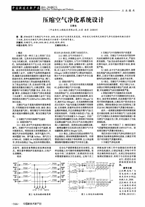
3-2油份 ,由于空气在压缩 过程 中,润滑
在 钢铁工 业 中 ,压缩 空气 也得 到普遍 的采 200mg/m3,如果空压机吸气 口附近环境 恶劣 , 油在高温气 流运动 的影 响下 ,油份 呈细微粒
用 ,随着 自动化程度 的提高和大量 国外先进 则大气 中含尘量将更 高 ,压缩空气 中含尘量 雾状 ,且部 分可 能生成 焦糊 物 ,并 沉积 在管
代 。如 风动 机械具有不 产生火花 、在 灰尘较 各种粉尘 (灰尘 、煤烟 、金 属粉末 等 ),这 些粉 在寒 冷地 区 ,水份 可能 在管道 中冻 结 ,影 响
多 的环境 中 ,也 能很好 地操 作 、且 无触 电危 尘在空压机的吸气过程 中被 吸人 。据有关资 更严重 。
险,适合 冲击 性和负荷 变化较 大的工作等 。 料 ,在工业 区大气 中含有 尘浓度高 时可达到
3.1水份 ,压缩 空气 中 的水份可使 各种
用 的动力源 ,它具有许 多 良好性 能和特点 ,
2.13粉尘 ,在 钢铁 企业 中 ,空压 机 站大 风动 机械部 件生 锈 ,电磁 动作 失灵 ,严 重 的
与 电力机 械 比较 ,在某 些部 门尚不能被 取 多设置在 厂区范围 内,大气 中不 同程度 含有 甚 至烧毁 ,气缸 无法动作或 动作不 准确等 。
0.7MPa时 ,压缩机 24小 时排 出的压缩空气 管道安装后未清洗干净的焊屑、尘土和金属 用户对压缩空气质量 的要求 。
中 ,所含水份 高达 73kg,经后冷却器处理后 , 锈蚀物均能增加压缩 空气 中的含 尘量。
5压缩空气净化处 理
及 信 号 、通 信设 备 等 都 应 该 是 调试 的重
2.1.1水份 ,在 空气 中或多或少都含有水 混入大量的油份 ,虽然经过 油过滤器 过滤 ,
浅谈机械制造企业压缩空气系统设计

浅谈机械制造企业压缩空气系统设计摘要:通过对机械制造企业用气特点及压缩空气设备性能分析,设计机械制造企业的压缩空气系统。
关键词:压缩空气系统机械制造企业工业企业生产过程中都使用压缩空气做为载能工质,生产和净化压缩空气的用电占企业生产用电量的10~20%左右,在企业规划设计时,做好压缩空气系统的规划设计,能有效降低公司能耗,减少生产成本,本文主要从空压机站房、设备选型、压缩空气管网等方面论述机械制造企业的压缩空气系统设计。
压缩空气在机械制造企业的主要用途是板材切割、设备控制、装配、喷涂、喷砂、吹扫等场合。
在生产过程压缩空气需求主要有以几个特点:①、压力从0.3MPa~1.5MPa都有设备使用,但主要集中在0.5MPa~0.65MPa范围内,只有切割机等小部分设备用气压力大于0.7MPa,铁屑及粉尘吹扫压力小于0.4MPa。
②、各零部件加工时间差异,生产过程中用气量波动大。
③、设备控制、装配等大部分设备、工艺用气含水量要求都低于4级(≦3℃),只有喷涂、试验及测量设备等少部分用气含水量要求在3级(≦-20℃)。
一、空压站设计1.1空压站选址目前输送压缩空气的管道主要有不锈钢、碳钢管、聚乙烯管道等。
因为受材质、制造工艺及使用过程中腐蚀影响,压缩空气管道存在一定的粗糙度,在输送压缩空气过程中,会产生压降,消耗能源,管道压降及能耗可用以下计算公式确定。
压降计算公式:△P压力=1.15(ρν2/2(103λL/d+∑Ꜫ))+10ρ,单位:paΡ--压缩空气密度;ν压缩空气流速;λ摩擦阻力系数;d管道内径;L管道长度;∑Ꜫ局部阻力系数总和管道压降产生能耗计算公式:∆P能耗=Ꜫ*(△P压降)/(p压力)*60:单位(kWh)例:一台空压机比功率为6kw/(m3/min),末端需求压力为0.7MPa,当使用DN100管径的碳钢管输送压缩空气时,求输送每立方米气体增加的每米能耗。
解:1、根据压降公式计算每米管道的压降:△P压力=1.15(ρν2/2(103λL/d+∑Ꜫ))+10ρ(h2-h1)=1.15(1.28*10*10/2(1000*0.0352*1/100))=157pa。
压缩空气系统简介

同时,压缩空气系统也面临着市场竞争加剧、技术更新换代、能源价格波动等方面的挑战,需要企业不 断提高技术研发能力和管理水平,以适应市场的变化。
压缩空气系统的未来发展方向及创新应用
未来发展方向
未来压缩空气系统将更加注重环保和能 效,通过技术创新和升级,提高产品的 性能和可靠性,同时加强智能化、模块 化、集成化等方面的研发和应用,以满 足市场的不断变化和需求。
02
选择合适的压缩机类型
根据使用需求和场地限制,选择合适的压缩机类型, 如活塞式、螺杆式或离心式。
03
考虑后处理设备
为满足生产工艺要求,需考虑后处理设备,如冷干机 、过滤器等。
04
设计合理的管路布局
根据场地布局和生产工艺流程,设计合理的压缩空气 管路布局。
05
考虑节能和环保因素
在设计过程中,需考虑系统的节能减排措施,如采用 变频技术、余热回收等。
压缩空气系统的选型依据及方法
01
02
03
04
05
根据生产工艺需求确定压 根据使用需求和场地限制 根据生产工艺要求选择合 根据场地布局和生产工艺
缩空气系统的流量和压力 选择合适的压缩机类型。 适的后处理设备。
流程设计合理的管路布局
等级。
。
根据节能减排要求选择合 适的节能环保设备。
压缩空气系统的节能减排措施
02
01
03
优点
动力来源可靠:压缩空气系统可以提供稳定可靠的气 源,适用于各种工业和市政领域。
适应性强:压缩空气系统可以根据不同的用气需求进 行灵活调整,满足各种工艺过程的需求。
压缩空气系统的优缺点
• 维护方便:压缩空气系统的各个组成部分相对独立,维护起来比较方便。
医用压缩空气供气系统设计与气体质量控制 李继斌 中国人民解放军总医院

一、 医用压缩空气的用途
医用压缩空气与医用氧气、吸引一样,是现代化医院集中供气系统的重要组成部分,其主
要用途为:
1、作为重症监护室、抢救室呼吸机的动力。 2、为病人,特别是重症病人提供氧气/空气混合气体。 3、作为手术室气动工具的动力。 4、作为牙科气动工具的动力。 5、作为供应室某些设备的动力。 6、作为理疗及康复治疗设备的动力。
以确保医用仪器不受污染,同时避免对病人身体健康的影响。而通常工业用空压机不能保证无
油,其含油量达 5ppm,使用两年后,有的甚至达到 10ppm 以上,严重影响病人健康,甚至造成
医疗事故。
2、 控制气源水份,压缩空气系统必须安装干燥机。一般空气中的水份皆呈气态,不易被
察觉其存在,但经空压机压缩及管路冷却后,则会凝结成液态水滴,例如:在大气温度 30℃,
医用压缩空气供气系统 设计与气体质量控制
李继斌 中国人民解放军总医院 北京 100853 摘要:本文重点论述的是医院中压缩空气供气系统的设计、建设和气体质量的控制和安全管理。 当我们在探讨医疗供气系统的质量时,实际上是在讨论伤病员安全问题。在讨论伤病员用气安 全时我们必须首先搞清楚供气系统是否安全。
准确测量、严格控制医用压缩空气水份含量、保证医用压缩空气质量,是减少气动医疗工 具及气动医疗仪器损坏、确保病人治疗安全的最重要措施之一。而严格控制医用压缩空气水份 含量的前提是准确测量水份含量,按不同原理,微量水测量方法有四种:电解法、露点法、电 容法、晶体振荡法等,其中露点法应用最普遍,灵敏度 1~0.1/10-6 ,但仪器价格昂贵。 六、 压缩空气站房设计
Hale Waihona Puke 2、微热再生吸咐式干燥机 品牌: 型号: 处理量: 工作压力: 工作温度: 环境温度: 压力露点: 电源: 额定功率: 重量: 空气接口管径: 外形尺寸:(L*W*H) 3、储气罐主要技术参数
《2.3 压缩空气》教学设计教学反思-2023-2024学年小学科学教科版17三年级上册

《压缩空气》教学设计方案(第一课时)一、教学目标:1. 知识与技能:了解空气可以被压缩的事实,理解空气压缩后的变化,能够解释相关现象。
2. 过程与方法:通过实验观察压缩空气的变化过程,培养观察和思考能力。
3. 情感态度与价值观:认识到科学无处不在,培养对科学的好奇心和求知欲。
二、教学重难点:1. 教学重点:通过实验观察压缩空气的变化过程,分析实验结果,得出结论。
2. 教学难点:理解空气压缩后的变化及其原理,能够解释相关现象。
三、教学准备:1. 实验器材:气球、皮球、气压计、橡皮筋等。
2. 多媒体素材:相关图片、视频等。
3. 课前布置学生预习相关内容,了解空气的基本性质。
四、教学过程:(一)引入新课1. 通过小游戏:吹气球,吹大一个瘪的气球需要更使劲,让学生感受到空气存在压力,而且力气越大,气球被吹得越大,空气压力就越大。
2. 提问:空气压力在我们生活中有哪些应用?让学生思考并讨论。
(二)新课教学1. 展示空气泵(打气筒)的图片,介绍空气泵的工作原理。
2. 讲解压缩空气的概念:把空气压缩后,空气会有很大的压力,这就是压缩空气。
3. 介绍空气泵的工作原理:当我们从打气筒的活塞推动空气经过橡胶管到达需要充气的轮胎时,空气被压缩了,产生了很大的压力。
这个压力会把轮胎压瘪,从而把轮胎紧紧地固定在轮毂上。
4. 提问:压缩空气有哪些应用?让学生思考并讨论。
5. 展示一些压缩空气的应用图片或视频,例如气垫船、轮胎充气、喷泉、气枪等。
6. 小组活动:让学生自己动手实验,把一个小球用塑料袋抽成真空后,从一端用力挤入空气,观察小球的反应。
让学生体验到空气被压缩后产生的巨大压力,从而加深对压缩空气的理解。
7. 提问:你们小组的实验结果是什么?让学生分享实验过程和感受。
8. 介绍压缩空气的优点和缺点,优点包括轻便、易于储存、使用方便等;缺点包括易燃易爆、有毒等。
(三)小结通过此次课程的学习,我们对喷雾剂这种产品的特点有了深入的了解。
压缩空气系统的节能设计注意事项

压缩空气系统的节能设计注意事项空压系统要做到最大化运行节能,应在设备选型、站房位置选择、管道安装设计时就应注意以下事项,做到最大化满足系统节能运行的条件:一、空压站房位置选择注意事项:空压站(或系统设备)的设立位置最基本应选择在通风良好、灰尘少、环境清洁的位置,如有条件,还应尽量选择环境湿度低的位置。
因为:环境温度越高,空压机的吸气温度越高,则空压机的压缩效率就越低;环境温度高,也将导致冷却效果差,不能有效降温和除去压缩空气中的水份,会增加后续冷却设备的负荷和能耗;灰尘多,则导致吸气过滤器(空滤)易堵塞,增加空压机运行能耗;灰尘多,易吸附在换热设备表面,降低其热交换效率,增加运行能耗;灰尘多,易导致空压机润滑油脏污,从而堵塞油气分离器及油滤,以及易形成油垢附在冷却器的油路管程内,降低换热器效率及增加运行能耗;空气湿度大,水份重,不但其压缩效率低,且增加后续冷却热负荷,都将导致运行能耗高。
现在的空压设备只需选型适当和维护适当,一般很少搬运,则比较合适的位置是远离尘源(如运输道路、产尘车间区)且在尘源的上风位的建筑楼顶上,建一个站房,房壁基本是通风百叶窗+多层纤维过滤网的模式。
空压站四周都采用百叶窗(如考虑台风等天气,可设置双层防水百叶窗,尽量防止雨水进入站内),可保证通风良好且风阻小,在百叶窗后加一道多层纤维过滤网,可起到初步过滤灰尘,清洁环境空气的作用,且其风阻小通风顺畅,这种滤网也易清洗和重复使用。
如能找到常年背阳、又是通风通道的位置,或是常年有大量冷源(如液氮、液氧的蒸发器等,不仅环境温度被降低,且环境湿度也相对低)散发的周围且更佳。
二、风冷类空压机及冷干机的安装位置考虑:风冷式空压机和冷干机都有换热器设备,如环境温度低、通风良好更能降低系统能耗。
这类设备多数会将大量热负荷直接排放到周围,如果其安装位置考虑不周,将直接影响设备的正常工作。
笔者见到一例,数台冷干机并排运行,刚好上一台的排风直接对准下一台冷干机的进风口位置,则后面的机台的压缩制冷系统经常出现高压保护跳机故障,在分析故障情况后,在各机台之间加装简易隔板,使机台的进风、排风错开,则情况得到解决。
压缩空气系统方案(最终)

压缩空气系统方案(最终)一、系统概述压缩空气系统作为工业生产中的重要辅助系统,承担着为各类气动设备提供稳定气源的重要任务。
本方案旨在为您打造一套高效、节能、稳定的压缩空气系统,以满足生产需求,降低运营成本,提高生产效率。
二、系统设计原则1. 安全可靠:确保系统在各种工况下安全稳定运行,降低故障率。
2. 节能高效:选用高效节能的设备,降低能源消耗,提高系统能效。
3. 灵活扩展:充分考虑未来生产需求,预留一定扩展空间,便于系统升级。
4. 易于维护:采用标准化、模块化设计,便于日常维护和故障排查。
三、系统组成1. 空气压缩机:选用螺杆式空气压缩机,具有高效、节能、噪音低等优点。
2. 后处理设备:包括冷冻干燥机、吸附式干燥机、精密过滤器等,确保输出空气质量。
3. 储气罐:用于储存压缩空气,平衡系统压力波动,确保气源稳定。
4. 输气管道:采用优质不锈钢管道,减少气体损耗,降低系统阻力。
5. 控制系统:实现对整个压缩空气系统的实时监控、故障诊断和自动调节。
四、系统配置1. 空气压缩机:根据生产需求,配置相应功率的空气压缩机,确保供气稳定。
2. 后处理设备:根据用气质量要求,配置合适的干燥机和过滤器。
3. 储气罐:根据用气量和压力波动情况,选择合适容积的储气罐。
4. 输气管道:根据车间布局,合理规划管道走向,降低管道阻力。
5. 控制系统:采用智能化控制系统,实现设备联动、故障预警等功能。
五、系统优势1. 节能效果显著:本方案选用的空气压缩机具有较高的能效比,结合优化的系统设计,能够有效降低能耗,为企业节约运营成本。
2. 稳定性高:系统采用高品质组件,保证了长期稳定运行,减少了因设备故障导致的停机时间。
4. 噪音低:选用低噪音空气压缩机,并结合有效的隔音措施,为员工营造一个更舒适的工作环境。
5. 维护成本低:系统采用模块化设计,便于快速更换故障部件,减少维护工作量。
六、实施步骤1. 现场勘查:深入了解企业现有设备、生产需求及现场条件,为系统设计提供依据。
《净化压缩空气系统》课件

02
方案设计
根据需求分析结果,制定系统 设计方案,包括预处理、主处 理、后处理等环节的设计。
03
设备选型
根据设计方案,选择合适的压 缩空气净化设备,如过滤器、 吸附剂、冷干机等。
04
系统集成
将各设备集成到系统中,进行 系统调试和优化,确保系统整 体性能达到最优。
压缩空气净化系统的设计案例
案例一
某机械制造企业压缩空气净化系统:该系统采用多级过滤器和活性炭吸附剂,有效去除压缩空气中的油、水、 尘埃等杂质,满足机械制造企业生产工艺对压缩空气质量的要求。
压缩空气系统的应用领域
01
02
03
工业生产
用于驱动气动工具、控制 设备、生产流程等。
公共设施
用于消防、紧急救援、公 共交通车辆等。
实验室
用于科研仪器、实验设备 等。
压缩空气系统的优缺点
能源效率高
压缩空气可以存储大量的能量,且在 需要时可以迅速释放。
清洁环保
压缩空气不会产生火花和排放有害物 质。
压缩空气系统的优缺点
• 使用方便:压缩空气可以随时随地使用,不受电源限制。
压缩空气系统的优缺点
维护成本高
压缩空气系统需要经常维 护和保养,以确保其正常 运转。
噪音大
空气压缩机等设备会产生 较大的噪音。
需要定期检查
压缩空气的质量和压力需 要定期检查,以确保其符 合使用要求。
02
压缩空气的净化原理
压缩空气的来源和特点
《净化压缩空气系统》PPT 课件
目录
• 压缩空气系统的概述 • 压缩空气的净化原理 • 压缩空气净化系统的设计 • 压缩空气净化系统的维护与保养
01
压缩空气系统的概述
- 1、下载文档前请自行甄别文档内容的完整性,平台不提供额外的编辑、内容补充、找答案等附加服务。
- 2、"仅部分预览"的文档,不可在线预览部分如存在完整性等问题,可反馈申请退款(可完整预览的文档不适用该条件!)。
- 3、如文档侵犯您的权益,请联系客服反馈,我们会尽快为您处理(人工客服工作时间:9:00-18:30)。
压缩空气系统设计摘要:一个好的压缩空气系统设计对于半导体芯片厂是非常重要的。
这篇论文主要是介绍压缩空气系统的设计思路。
本文主要讲述一下内容: 总体目标、气体要求、扩充策略、维护保养、空气流通、气体品质与压力、系统中的压力损失、系统框架等。
关键字:压缩空气;压力;容量;质量abstract: a well designed compressed air system is very important for a semiconductor wafer fab operation. this paper gave the designer of compressed air system design. the following topics covered in this paper: overall objective, air demand, expansion strategy, maintenance considerations, ventilation, air quality, air pressure, pressure loss in air system, information needed by supplier, air receiver sizing, system layout. even you are designing a new compressed air system or you want to get your exist system expanded, you will find this paper is helpful for your project.key words: air compressor; pressure; capacity; quality compressed air system designi overall objective of compressed air system design meet average air demandmeet peak air demandprovides the quality of air needed for the applicationprovides at least the minimum required air pressure provide capability for future expansionprovide capability for easy maintenanceprovides sufficient ventilationkeep the project cost within budgetminimize operation costii air demandair demand can be determined from flow measurements or by observation of exist compressor load factors in an existing system. an air survey can be done on an existing system or for a proposed system to determine air demand. if an existing system has the compressors running at 100% use factor and is still not maintaining design pressure, plant required capacity chart located in this section can be used to determine how much additional capacity is required to bring the pressure back up to the design point.for example: if existing plant capacity is 2000 scfm, existing pressure is 90 psi, but the required pressure is 110 psi. we assume load factor is 100%,the additional capacity required for each 1000 scfm (existing) can be200scfm?? =400scfmdetermined in the chart : 200scfm/1000scfm. so the totaladditional capacity is :total required capacity is 2400 scfm, as shown in the above chart.iii expansion strategyone approach to future expansion requirements is to oversize the existing system. this may take the form of one or more compressors designed to run at less than full load to meet present demand allowing for increased air production in the future. it may also take the form of installing one or more additional compressors the are on standby until needed. another approach is to design the compressor room and piping system such that additional compression equipments can be added later.iv maintenance considerationsall compressors require routine preventive maintenance and nearly all compressors eventually experience an unexpected outage. if the cost to an outage is extreme, it is wise to consider a stand-by compressor in the system. when maintenance is required, it is necessary to have sufficient room to work on the compressor system. make sure there is enough clearance around and above the components to facilitate maintenance. minimum clearances can be obtained from the equipment supplier for specific item, overheadlifting capability is useful.if the compressor intake is located indoors, sufficient air must be available to pass through the intake filter and into the compressor. this need for ventilation, however, is minor compared to the ventilation required for removal of heat. it is generally true that:□an air cooled compressor rejects about 42.4 btu/min per bhp to the air around itself.□a water cooled compressor rejects between 13% and 30% of that amount (the rest is rejected to the cooling water). based on a 330 bhp compressor:get specific heat rejection data from the equipment manufacturer in order to determine ventilation requirement. the specific heat of air at 14.7 psia, 60deg f is 0.018336 but/cubic ft-deg f. in order to ventilate a room for a 330 bhp air cooled unit allowing a 10 deg f temperature rise in the cooling air would require the following;(330 x 42.4 btu/min)x(cubic ft-deg f/0.018336 btu)/(10 deg f)=76,309 cfm of ventilating airv air quality / pressurethe quality of is determined by it’s intended use. dewpoint requirements can be addressed with aftercoolers and dryers. oil content can be addressed with oil free compressors or filtration. particulate matter can be addressed with piping materials and filtration. refer to the manufacturer’s catalog to select the aftercooler, dryer and filter. determine air pressure requirements at the point of use. most air pressure requirements are satisfied by selection of the proper compressor design pressure and a properly designed piping system. low pressure requirements are often satisfied from the plant air system through a pressure regulator. when constant pressure is required at the point of use and normal system pressure fluctuations are a problem, a point of use pressure regulator is generally the solution. in this last case system pressure must be designed to always be above the desired pressure after the regulator.vi pressure loss in air systemsdetermine air pressure requirements at the point of use. most air pressure requirements are satisfied by selection of the proper compressor design pressure and a properly designed piping system. low pressure requirements are often satisfied from the plant air system through a pressure regulator, when constant pressure is required at the point of use and normalsystem pressure fluctuations are problem, a point of use pressure regulator is generally the solution. in this last case system pressure must be designed to always be above the desired pressure after the regulator.pressure loss in air systemspressure drops for components such as aftercoolers, dryers and filters should be obtained from the manufacturer. the expected pressure drop through the piping system can be estimated using the pressure loss tables and equivalent length table.vii information needed by supplierthe supplier should be given the following design conditions:barometer=psiainlet air temperature=deg frelative humidity=%cooling water temperature=deg f (if applicable) discharge pressure=psigair flow=icfm or acfm or scfmdefinitions:icfm - inlet cubic feet per minute. this is a measurementof the air entering the compressor.acfm - actual cubic feet per minute. this is measurement of actual air delivered, referred to inlet conditions. scfm-standard cubic feet per minute delivered. this is a measure of delivered capacity rapacity referred to some standard set of conditions. the most common set of standard conditions are 14.7psia, 60 deg f and 0% relative humidity. the supplier should also be given the minimum and maximum inlet air temperatures. if it is a water cooled application, minimum and maximum cooling water temperatures should also be stated.viii air receiver sizingthe air receiver size can be determined based on manufacturer’s recommendation or system requirements.the following formula can be used to size a tank based on system needs.v: receiver capacity, in cubic feett: compressor off line time prior to loading, in minutes p2: final receiver pressure when the compressor just be off ling, in psigp1: initial receiver pressure when the compressor starts, in psigc: actual compressor delivery, acfmpa: atmospheric pressure, psiaix system layoutthe following picture shows the general layout for compressed air system.作者简介:张榕,男,汉族,天津人;中级工程师,中芯国际集成电路制造(天津)有限公司,研究方向:机电/控制/洁净室。
