数据手册PM-T7,PM-T7M激光颗粒物传感器产品数据手册V2.2
激光粉尘PM2.5传感器讲解
(型号:ZH03
使用说明书
版本号:1.3
实施日期:2015.08.12
郑州炜盛电子科技有限公司Zhengzhou Winsen Electronic Technology Co., Ltd
声明
本说明书版权属郑州炜盛电子科技有限公司(以下称本公司所有,未经书面许可,本说明书任何部分不得复制、翻译、存储于数据库或检索系统内,也不可以电子、翻拍、录音等任何手段进行传播。
第3位第4位PM1.0浓度(标准颗粒物PM2.5浓度(标准颗粒物PM10浓度(标准颗粒物PM1.0浓度(大气环境下PM2.5浓度(大气环境下PM10浓度(大气环境下保留
第5位第6位第7位第8位第9位第10位第11位第12位第13位第14位第15位第16位第17位第18位第19位第20位第21位第22位第23位
保留保留数据和校验高8位校验=第0位+……+第21位数据和校验低8位
3、问答式
粉尘模组系列0起始位0xFF 1保留0x01 2命令0x86 3保留0x00 4保留0x00 5保留0x00 6保留0x00 7保留0x00 8校验值0x79传感器返回值格式如下,电:壹捌陆叁捌伍壹陆壹玖贰0起始位0xFF 1命令0x86 2高位(ug/m3 0x00 3低位(ug/m3 0x2A 4保留0x00 5保留0x00 6 7 8校验值0x30高位(ppb高位(ppb 0x00 0x20校验和计算/********************************************************************** *函数名: unsigned char FucCheckSum(uchar *i,ucharln *功能描述:求和校验(取发送、接收协议的1\2\3\4\5\6\7的和取反+1)*函数说明:将数组的元素1-倒数第二个元素相加后取反+1(元素个数必须大于2)扣扣:贰捌伍零陆零贰陆零伍**********************************************************************/ unsigned char FucCheckSum(unsigned char *i,unsigned char ln { unsigned char j,tempq=0; i+=1; for(j=0;j<(ln-2;j++ { tempq+=*i; i++; } tempq=(~tempq+1; return(tempq; }注意事项1、禁止改动、移位电子元件安装状态。2、模组不可经受过度的撞击或震动。3、传感器建议垂直安装,增长风扇使用寿命4、安装时保证粉尘采集孔空气流通正常5、避免粘性粒子进入传感器,防潮湿,以防影响性能。以诚为本、信守承诺创造完美、服务社会
PMS7XXX颗粒物传感器中文说明书

起始符 1
0x42
起始符 2
0x4d
帧长度高八位
……
帧长度低八位
……
数据 1 高八位
……
数据 1 低八位
……
数据 2 高八位
……
数据 2 低八位
……
数据 3 高八位
……
数据 3 低八位
……
数据 4 高八位
……
数据 4 低八位
……
数据 5 高八位
……
数据 5 低八位
……
数据 6 高八位
…….
数据 6 低八位
工作原理 本传感器采用激光散射原理。即令激光照射在空气中的悬浮颗粒物上 产生散射,同时在某一特定角度收集散射光,得到散射光强随时间变 化的曲线。进而微处理器利用基于米氏(MIE)理论的算法,得出颗 粒物的等效粒径及单位体积内不同粒径的颗粒物数量。传感器各功能 部分框图如图 1 所示
北京攀藤科技有限公司 2015 年产品数据手册
表 1 传感器技术指标
指标
0.3~1.0;1.0~2.5;2.5~10 50%@0.3um 98%@>=0.5 um 0.1 ≤10 5.0 100 ≤200 L <0.8 @3.3 H >2.7@3.3 -20~+50 0~99% ≥3 48×37×12
单位
微米(μ m)
升(L) 秒(s) 伏特(V) 毫安(mA) 微安(μ A) 伏特(V) 摄氏度(℃)
北京攀藤科技有限公司 2015 年产品数据手册
DSENSOR
数字式通用颗粒物浓度传感器
PMS70XX 系列数据手册
主要特性 零错误报警率 实时响应 数据准确 最小分辨粒径 0.3 微米
空气质量监测PM指标解读
空气质量监测PM指标解读在如今空气污染日益严重的环境下,人们开始更加重视和关注空气质量的监测。
其中,PM指标被广泛用来评估空气中颗粒物的浓度和质量,并对公众的健康产生重要影响。
本文将对PM指标进行解读,帮助读者更好地理解空气质量监测结果。
1. 什么是PM指标PM指标代表颗粒物污染的浓度和质量,其中PM2.5和PM10是最常见的两个指标。
PM2.5表示直径小于等于2.5微米的颗粒物,而PM10则表示直径小于等于10微米的颗粒物。
这些颗粒物主要来自于燃烧过程、车辆尾气排放、工业废气排放等,其大小越小,对健康的危害也就越大。
2. PM指标与健康影响空气中的PM指标与人类健康之间存在密切的关联。
由于颗粒物微小且轻便,它们能够携带着许多有害物质,如重金属、有机物和细菌等,穿过人体的呼吸系统进入到肺部。
长期暴露于高浓度的PM2.5和PM10会导致呼吸系统疾病的增加,如哮喘、慢性支气管炎和肺癌等。
此外,PM指标还与心血管疾病、过敏反应和免疫系统异常等问题相关。
3. PM指标的意义PM指标的测量结果对公众具有重要意义。
一方面,它们能够提供空气污染程度的实时数据,帮助政府和相关部门制定环保政策和措施,并警示公众关注健康风险。
另一方面,公众可以根据PM指标的情况,调整自己的日常行为,如减少户外活动时间、佩戴口罩等,以保护自己的健康。
4. PM指标的解读在进行空气质量监测后,会得到相应的PM指标数值。
如何正确解读这些数据是至关重要的。
根据国家环境保护标准,空气质量可以分为六个级别:优、良、轻度污染、中度污染、重度污染和严重污染。
当PM2.5浓度小于35微克/立方米,PM10浓度小于50微克/立方米时,空气质量属于优级,对健康几乎没有影响。
当PM2.5浓度介于36-75微克/立方米,PM10浓度介于51-150微克/立方米时,空气质量属于良级,对健康影响较小。
当PM2.5浓度介于76-115微克/立方米,PM10浓度介于151-250微克/立方米时,空气质量属于轻度污染,对健康可能有一定程度的影响。
PM操作手册

集团股份有限公司SAP—PM操作手册目录一、功能位置 (3)1.创建功能位置:IL01 (3)2。
修改功能位置:IL02 (5)3。
显示功能位置:(IL03) (7)4.按功能位置结构展开(IH01) (8)二、固定资产类设备新增 (9)1.固定资产类新增提报 (9)2.供应部建立采购订单ME21N (9)3.收货MIGO (9)4.设备到货,完善设备主数据 (9)三、项目设备 (13)1.项目利用旧设备 (14)2.项目采购新设备 (14)四、设备BOM的新增、修改 (14)1。
新增单个设备BOM (14)2。
修改设备BOM (21)3.显示设备BOM (21)4.批量导入设备BOM (21)五、故障知识库的新增、修改 (21)1。
故障现象的新增、修改 (21)2.故障原因新增、修改 (24)六、状态监测点的新增、修改 (24)1.创建状态监测点 (24)2.修改状态监测点信息 (26)3。
单个查询状态监测点的信息 (26)4。
批量显示计量点 (26)5.录入状态监测点数据记录 (27)6。
显示计量凭证(状态监测记录) (29)七、密封点 (30)1。
根据功能位置创建密封点 (30)2。
修改密封点信息 (32)3.查询计量点(密封点)信息 (33)4.密封点泄漏率统计报表查询 (33)八、换油点 (33)1.创建换油点 (33)2.修改换油点信息 (35)3。
查询计量点(换油点)信息 (35)4。
维护换油信息 (35)5。
换油执行 (36)6.换油历史记录 (36)九、测厚点 (37)1。
创建测厚点 (37)2.修改测厚点信息 (38)3。
查询计量点(测厚点)信息 (39)4。
测厚监控平台 (39)5.测厚执行 (40)6。
测厚历史记录 (40)十、设备维修流程 (40)1.职能部门创建维修通知单 (41)2.建立维修订单 (45)3。
领料 (54)4.维修执行--内部维修(车间内部维修) (54)5.维修执行—-外部维修(车间外) (55)6。
PMS200系列颗粒物传感器使用说明书v1.0.2

PMS200系列颗粒物传感器使用说明书1.产品简介PMS200系列是基于激光散射原理的颗粒物浓度测量传感器。
它使用稳定性极好的激光LED和高灵敏度的探测器,对颗粒物的个数和粒径分布进行精确测量,输出精确的颗粒物浓度值。
它体积小巧、支持数字通讯,便于集成到其他产品中。
PMS200是常规颗粒物传感器,PMS200T是颗粒物和温湿度一体式传感器。
2.产品特点●激光散射实现精准测量●零误报率●实时响应●最小分辨粒径0.3微米3.工作原理PMS200系列颗粒物传感器采用激光散射原理,即令激光照射在空气中的悬浮颗粒物上产生散射,同时在某一特定角度收集散射光,得到散射光强随时间变化的曲线,再利用基于米氏(MIE)理论的算法,得出颗粒物的等效粒径及单位体积内不同粒径的颗粒物浓度。
传感器工作原理如图1所示。
图1 PMS200系列颗粒物传感器工作原理示意图4.技术指标5.输出接口PMS200输出颗粒物的质量浓度,PMS200T输出颗粒物的质量浓度和温湿度。
(1)接口描述数据接口:其中2pin为串行数据通讯接口,采用通用异步收发协议(UART);所有电平均为3.3VTTL电平。
(2)接口管脚定义说明图2 PMS200颗粒物传感器的接口管脚定义注:SET=1,表示模块工作在连续采样方式,模块在每一次采样结束后主动上传采样数据,数据更新时间小于2s。
6.外形尺寸单位:毫米(mm)图3 PMS200颗粒物传感器外形尺寸示意图默认波特率:9600bps 校验位:无停止位:1位默认波特率:9600bps 校验位:无停止位:1位。
数据手册PM-E5激光颗粒物传感器产品数据手册V2.2
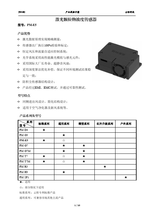
同侧进出风设计,简化结构设计; 适用于空气净化器及新风系统等。
系列 型号
PM-D4
标准系列 ★
通用系列
PM-G3
★
PM-E5
★
☆
PM-G7
★
PM-G7M
★
PM-T7
★
☆
PM-T7M
★
☆
PM-R3
PM-H3
★
PM-SP1 ★:适用
☆:部分情况下适用
标准系列 :云彤专利标准产品
通用系列 :可兼容市场其他主流产品
温度特性 长期性能 振动工作 电源波动
标准密闭温度室,温度缓慢变化,从-
5℃~50℃ ,每 10℃恒定 20min,测
量传感器一致性(温度包含最大最小
值测试点)
1.在烟雾环境下测试,(0~500)μg/m3 并达如下
温度(25±5)℃,湿度(20~70)%RH, 运行时间 1000H
一致性指标: (0~100)μg/m3 区间,满足一致性误差小于 ±15μg/m3;
1.主机通讯协议格式
特征字节 1 特征字节 2
0x42
0x4d
2.指令及特征字节定义
指令字节 CMD
状态字节 1 状态字节 2 校验字节 1 校验字节 2
DATAH
DATAL
LRCH
LRCL
CMD 0xe2 0xe1
0xe4
DATAH X X
X
DATAL X
00H-被动式 01H-主动式 00H-待机模式 01H-正常模式
5 / 10
PM-E5
产品数据手册
数据帧校验检测处理例程
/********************************************** 函数名:check_sum 函数功能:检测传感器的数据包校验是否正确 输入参数:*dat ---数据存放地址 返回值: 校验正确--0xff 校验错误返回--0x00 ***********************************************/ unsigned char check_sum(unsigned char *dat) {
Series PMT2 粒子传感器规格与安装运行说明书

The Series PMT2 Particulate Transmitter is designed to measure particulate emission levels from dust collector discharge. Using DC coupled electrostatic induction sensing technology, the transmitter monitors a pA current that is generated as particulate passes near the probe; a 4-20 mA signal will vary based on the particulate level. The PMT2 offers 6 sensitivity ranges allowing the user to choose the range that will best fit the application. The range and test selector switch can also be set to output a 4 mA or 20 mA signal to assist with set up or trouble shooting. Averaging time setting can be used to dampen the signal if desired.FEATURES/BENEFITS• Simple 2-wire installation for PLC and control panels• Non-stick PTFE coated probe to prevent false readings from moist and conductive dusts, condensate, and dust buildup• Remote zero calibration helps to decrease maintenance timeOPERATING PRINCIPLETechnologyThe PMT2 utilizes a highly reliable DC coupled electrostatic induction sensing technology. The sensor probe is mounted in an airflow stream such as a pipe, duct or stack. The inductive effect takes place when particulate passes near the probe transferring a charge from the particulate to the probe. A microprocessor filters and processes the signal into a output that is linear to the mass concentration of particulate. The PTFE coated probe ensures reliable operation with all types of particulate including moist powders and highly conductive dusts. The PTFE coated probe eliminates the need for an air purge and keeps maintenance to a minimum.Particulate MonitoringThe PMT2 is specifically designed to continuously monitor the particulate levels in air flow from stacks or other emission points being passed through a filter within an air filtration system. The transmitter should be installed in the exhaust ductwork and can be used in conjunction with various types of bag, ceramic, cartridge or cyclone filters. When the PMT2 is first installed a baseline reading must be measured and noted. This baseline reading is application dependent and should be measured independently for each installation. From this baseline the operator will monitor output signal from the PMT2. The increase in mA output indicates a rising level of particulate in the air stream which indicates that filters are either wearing out or broken.The PMT2 is designed to give a proportional output based on the particulate levels in a duct or pipe, it is not designed to output a signal based on the particulate volumetric flow. Different types of particulate carry different charges, meaning that two particulates flowing at the same volumetric flow rate could have different output response. The PMT2 is designed to find a baseline under ideal operating conditions and allow an operator to watch the output signal for increases that would signify the bags or filters are starting to wear or break. The six sensitivity ranges allow the PMT2 to monitor particulates with low charge properties or high charge properties. As a reference, Table 1 lists particulate charge properties and the suggested range.INSTALLATIONUnpackingRemove the PMT2 from the shipping carton and inspect for damage. If damage is found, notify the carrier immediately.LocationThe following factors should be considered when determining the installation location for the PMT2:• Make sure the transmitter is rated for the area classification it will be mounted in. • Mount the transmitter in a location that will not exceed the temperature and pressure ratings listed in the specifications. The process pressure should not exceed 30 psi (2 bar).• Make sure the 4-20 mA signal wires are not sharing the same conduit with high voltage power wires.• Make sure the location the transmitter is mounted in meets the NEMA or IP rating for the enclosure.• Locate the transmitter in a location were it can be accessed in case service isrequired.The PMT2 should be mounted in a grounded metal stack, pipe or duct. It should not be mounted in fiberglass or plastic stacks, pipes or ducts. The sensing probe should reach 1/2 to 2/3 the way across the stack, pipe or duct to ensure accurate readings. For the most stable and accurate readings it is recommended to mount the PMT2 in a location where the air flow is as laminar as possible. Avoid mounting the transmitter close to blowers and dampers that cause turbulence. It is ideal to mount the PMT2 in an area with two upstream duct diameters and one down stream duct diameter that are free of turbulent causing objects. The sensing probe is coated in a non-stick PTFE preventing material from coating the probe reducing the need for cleaning or an air purge.Table 1: Suggested rangesCONTROL DRAWING UL LISTED INTRINSIC SAFETY (SUFFIX U2):UL Listed Intrinsically Safe for use in Class I Div. 1 Groups C and D; Class II Div. 1Groups E, F and G; Class III Div. 1; Class I Zone 0 AEx ia IIB T4 Ga; Class I Zone 0 Ex ia IIB T4 Ga; T4@63°C when installed in accordance with Control Drawing 001744-48on page 6 of this document.ATEX COMPLIANT (SUFFIX A2)II 1 G Ex ia IIB T4 Ga (-40°C ≤ Tamb ≤ 63°C) (-40°C ≤ T Process ≤ 120°C) / II 1 D Ex iaIIIC T120°C Da (-40°C ≤ Tamb ≤ 63°C) (-40°C ≤ T Process≤ 120°C) when installed inaccordance with Control Drawing 001744-81 on page 7 of this document.IECEx COMPLIANT (SUFFIX A2)Ex ia IIB T4 Ga (-40°C ≤ Tamb ≤ 63°C) (-40°C ≤ T Process ≤ 120°C) / Ex ia IIIC T120°CDa (-40°C ≤ Tamb ≤ 63°C) (-40°C ≤ T Process ≤ 120°C) when installed in accordancewith Control Drawing 001744-81 on page 7 of this document.INTRINSIC SAFETY INPUT PARAMETERS:4-20 mA Signal, Vmax (Ui) = 28 V; Imax (li) = 93 mA; Ci = .022 μF; Li = 0.373 mH;Pmax (Pi) = 651 mWRemote Zero, Vmax (Ui) = 28 V; Imax (li) = 93 mA; Ci = Negligible; Li = 0 mH; Pmax(Pi) = 651 mWPOWER SUPPLY REQUIREMENTS The maximum DC power supply is 28 VDC. The minimum required DC power supply is based upon the following:1. Minimum DC voltage requirement of the Model PMT2.2. Total load resistance.3. Total leadwire resistance.4. Zener barrier voltage drop (Model PMT2-XX-X-X2 only).The formula for calculating the DC Power Supply is:VDC = VPMT2 + VLOAD + VLEADWIRE + VBARRIER Where VPMT2 = 9.5 V VLOAD = Total load resistance X 20 mA VLEADWIRE = Total leadwire resistance X 20 mA VBARRIER = 8.1 V (Typical zener barrier voltage drop for this application)Example 1: Calculate minimum DC power supply for intrinsically safe models Step 1 VPMT2 = 9.5 V Step 2 Calculate VLOAD. Using the industry standard 250 Ω conversion resistor, VLOAD = 250 X 20 mA = 5 V.Step 3 Calculate VLEADWIRE. For this example assume a leadwire resistance of 10 Ω, VLEADWIRE = 10 X 20 mA = 0.2 V Step 4 VBARRIER = 8.1 V Step 5 VDC = VPMT2 + VLOAD + VLEADWIRE + VBARRIER = 9.5 + 5 + 0.2 + 8.1 = 22.8 V CONTROLS Zero Switch (see Figure 2)Press and hold the switch for 3 seconds and the PMT2 will digitally re-zero. It is recommended to re-zero after a filter failure or filter changes. Re-zeroing should only be done when there is no air flow in the duct.Averaging Time Selection Switch The PMT2 will average the output for the selected amount of time. This will dampen output spikes caused during normal filter cleaning cycles. Range and Test Selection Switch There are 6 sensitivity ranges that can be selected based on the material the PMT2 will be sensing (see Table 1). There is also an option to output a 4 mA or 20 mA signal, these options can assist in the installation of the transmitter or trouble shooting. is neededINTRINSIC SAFETY SPECIFIC CONDITIONS OF USETo maintain Intrinsic Safety the following cautions should betaken:• 4-20 mA signal and remote zero must be treated as separate circuits• Enclosure parts are constructed of aluminum. Enclosure must be protected fromignition hazard due to impact or friction• All openings to enclosure must be sealed using suitable glands and/or plug main-taining a minimum IP rating of IP66 for UL Listed models and IP65 for ATEX/IECExcompliant models• Substitution of parts may impair Intrinsic Safety.LIVE MAINTENANCE PROCEDURE Live maintenance of Zero, Averaging Time, Range and Test controls cannot be performed when a flammable or combustible atmosphere is present.Figure 1: General installation wiring (non-IS)REMOTE ZERO SWITCH (IF USED)4321REMOTE ZERO 4-20 mA Figure 2Zero switch Range and test Averaging time Grounding screwSET UPMountingMake sure the PMT2 is securely mounted to the stack, pipe or duct to prevent vibrationduring operation. Make sure the transmitter is grounded properly.Control Signal Set UpCheck the power supply wiring to make sure the polarity is correct before poweringthe PMT2. Turn the power on to the transmitter and turn the Range and Test selectorswitch to 4 mA (position 2). The PMT should output 4 mA, check the output with amulti-meter or at the device (PLC, Display, etc.) receiving the output signal. Once it isverified the 4 mA signal is being received, switch the Range and Test selector switch to20 mA (position 1) and repeat the process. If the output is 0 mA, make sure the powersupply is on and check for loose wires.Range and Test SelectionWhen selecting one of the 6 available ranges, the baseline and maximum peak signalsthat take place during filter cleaning must be taken into account. The selected rangesshould have enough resolution to monitor the baseline and capture the maximumpeaks during a cleaning cycle. The four linear ranges output 4 mA at 5 pA and 20 mAat maximum range. The two logarithmic ranges have finer resolution at the low end ofthe ranges and less at the high end.LOGARITHMIC RANGE The logarithmic ranges offer a prolonged low-end of the scale while the high-end of the range is compressed. This offers better resolution for the baseline monitoring and still allows the operator to see the particulate spikes during cleaning cycles. Logarithmic ranges are recommended for filter bags since they have a greater tendency for particulate spikes during cleaning cycles.LOGARITHMIC RANGE EQUATIONS pA = Measured (pA) Picoamps M = Measured (mA) Milliamps from the PMT2R = 2 (for Logarithmic Range 5 to 500 pA)R = 3 (for Logarithmic Range 5 to 5000 pA)Example 1: Logarithmic Range 5 to 500 pA with current output of 12 mA:Example 2: Logarithmic Range 5 to 5000 pA with current output of 14 mA:SETTING EMISSION LEVEL ALARMS The PMT2 will provide a 4-20 mA signal based on the range selected at set up. Alarms can be programmed in the PLC or control system based on the 4-20 mA signal from the particulate transmitter. It is suggested to set two alarm set points. One alarm set point to monitor the emission spikes and the second alarm to detect an increase in the baseline. The alarm monitoring the emission spikes should be set to identify changes in the spikes caused by the cleaning cycles. As filters become worn, the spike’s height and duration will increase. The emission spike frequency will also increase because the filters will require more frequent cleaning as they wear out. If there is a continuous output above the emission spike alarm, it is more than likely a filter has torn and should be changed right away. The baseline alarm should detect an increase in the baseline reading. The type of dust collector and facility regulations will dictate where the baseline alarm has to be set. Typically the baseline alarm should be set 4 to 5 times over the initial baseline reading measurement when filters are first installed. So, if the baseline is 10 pA the base line alarm should be set between 40 pA and 50 pA. It is recommended to set a time delay in the PLC or control panel alarm to prevent false alarms during cleaning cycles. When the output signal from the PMT2 is continuously above baseline alarm it is time to replace the filters. If the emission spikes have increased yet the baseline remains unchanged, it’s an early indication that the filters are starting to wear out andwill need to be changed soon.Table 2: Range and test switchFigure 3: Typical filter emissionsTIMEpA = 10 x R + 0.699(M-4)16()pA = 10 x 2 + 0.699pA = 50(12-4)16()pA = 10 x 3 + 0.699pA = 375(14-4)16()AVERAGING SELECTION The PMT2 offers a digital averaging function because of the irregular flow of particulatesand the spikes during cleaning cycles. There are ten options for averaging rangingfrom 1 to 360 seconds. The digital averaging takes a running average of the readingsfor the selected amount of time. This will dampen output spikes from particulatefluctuations that could trip alarm settings. It is important to select an averaging settingthat will allow the operator to see the cleaning cycles. It is recommended to monitor the baseline trend and peak to peak trend between cleaning cycles.ZERO CALIBRATION Even though the PMT2 will come zeroed from the factory it is recommended to zerothe transmitter after installation to ensure the best accuracy. When zeroing the PMT2, make sure the dust collector is shut down and there is no air flow in the duct, stack orpipe the transmitter is monitoring. It is recommended to re-zero the PMT2 once every12 months for optimal performance. Please check your local laws and regulations asclean air standards may require zero calibration on a certain time schedule basedon application. There are two ways the PMT2 can be zeroed. The first method iswith the zero button on the front of the transmitter. Press and hold the button for 3seconds and the transmitter will begin zeroing. The second method is the remote zero.Supply DC voltage as shown in Figure 4 across the zero terminals on the back ofthe transmitter for at least 3 seconds for the transmitter to start zeroing. While thetransmitter is zeroing, the PMT2 will output about 3.5 mA. The zero function will takeapproximately 3 minutes. When zeroing is complete the output will return to a normaloutput signal and the transmitter is ready for operation.Figure 4: Remote zero and zero switchNote: Do not zero the PMT2 while the dust collector is in operation.Remote zero10-28 V -+MAINTENANCE/REPAIR Upon final installation of the Series PMT2, no routine maintenance is required. The Series PMT2 is not field serviceable and should be returned if repair is needed. Field repair should not be attempted and may void warranty.WARRANTY/RETURN Refer to “Terms and Conditions of Sales” in our catalog and on our website. Contact customer service to receive a Return Goods Authorization number before shipping the product back for repair. Be sure to include a brief description of the problem plus anyadditional application notes.NOTES__________________________________________________________________________________________________________________________________________ __________________________________________________________________________________________________________________________________________ __________________________________________________________________________________________________________________________________________ __________________________________________________________________________________________________________________________________________ __________________________________________________________________________________________________________________________________________ __________________________________________________________________________________________________________________________________________ __________________________________________________________________________________________________________________________________________ __________________________________________________________________________________________________________________________________________ __________________________________________________________________________________________________________________________________________ __________________________________________________________________________________________________________________________________________ __________________________________________________________________________________________________________________________________________ __________________________________________________________________________________________________________________________________________ __________________________________________________________________________________________________________________________________________ __________________________________________________________________________________________________________________________________________ __________________________________________________________________________________________________________________________________________ __________________________________________________________________________________________________________________________________________ __________________________________________________________________________________________________________________________________________ __________________________________________________________________________________________________________________________________________ __________________________________________________________________________________________________________________________________________ __________________________________________________________________________________________________________________________________________ __________________________________________________________________________________________________________________________________________ __________________________________________________________________________________________________________________________________________ __________________________________________________________________________________________________________________________________________ __________________________________________________________________________________________________________________________________________ __________________________________________________________________________________________________________________________________________©Copyright 2021 Dwyer Instruments, Inc.Printed in U.S.A. 8/21FR# 444122-00 Rev. 3。
数字式通用颗粒物浓度传感器PMSX0XX系列数据手册V12

数字式通用颗粒物浓度传感器PMSX0XX 系列数据手册 V1.2主要特性零错误报警率实时响应数据准确最小分辨粒径 0.3微米概述PMSX0XX 系列是一款数字式通用颗粒物浓度传感器,可以用于获得单位体积内空气中悬浮颗粒物个数及质量,即颗粒物浓度,并以数字接口形式输出。
本传感器可嵌入各种与空气中悬浮颗粒物浓度相关的仪器仪表或环境改善设备,为其提供及时准确的浓度数据。
工作原理传感器采用激光散射原理。
即令激光照射在空气中的悬浮颗粒物上产生散射,同时在某一特定角度收集散射光,得到散射光强随时间变化的曲线。
进而微处理器利用基于米氏(MIE )理论的算法,得出颗粒物的等效粒径及单位体积内不同粒径的颗粒物数量。
传感器各功能部分框图如图所示传感器功能框图表1 传感器技术指标参数 指标单位 测量范围 0.3~1.0;1.0~2.5;2.5~10微米(μm ) 计数效率 50%@0.3u m 98%@>=0.5u m(略) 称准体积 0.1 升(L )响应时间≤10秒(s)直流供电电压5.0伏特(V)最大工作电流120毫安(m A)待机电流≤200微安(μA)数据接口电平L <0.8 @3.3 H >2.7@3.3 伏特(V)工作温度范围-20~+50摄氏度(℃)工作湿度范围0~99%(略)平均无故障时间≥3年(Y)最大尺寸65×42×23毫米(mm)输出结果主要输出为单位体积内各浓度颗粒物质量以及个数(视具体型号)数字接口1.接口描述数据接口:其中2针为串行数据通信接口,采用通用异步收发协议(UART);1针为控制信号接口,采用高低电平控制,所有电平均为 3.3VTTL电平。
2.接口管脚定义说明图2 数字接口管脚定义PIN1 VCC 电源正5VPIN2 GND 电源负PIN3 SET 设置管脚/TTL电平@3.3VPIN4 RXD 串口接收管脚/TTL电平@3.3VPIN5 TXD 串口发送管脚/TTL电平@3.3VPIN6 RESET 模块复位信号/TTL电平@3.3VPIN7\8 NC 悬空注:SET=1 模块工作在连续采样方式下,模块在每一次采样结束后主动上传采样数据,采样响应时间小于600 毫秒,数据更新时间小于2 秒。
- 1、下载文档前请自行甄别文档内容的完整性,平台不提供额外的编辑、内容补充、找答案等附加服务。
- 2、"仅部分预览"的文档,不可在线预览部分如存在完整性等问题,可反馈申请退款(可完整预览的文档不适用该条件!)。
- 3、如文档侵犯您的权益,请联系客服反馈,我们会尽快为您处理(人工客服工作时间:9:00-18:30)。
云彤科技
1.主机通讯协议格式
特征字节 1 特征字节 2
0x42
0x4d
指令字节 CMD
状态字节 1 状态字节 2 校验字节 1 校验字节 2
DATAH
DATAL
LRCH
LRCL
2.指令及特征字节定义
CMD 0xe2 0xe1
0xe4
DATAH X X
X
DATAL X
00H-被动式 01H-主动式 00H-待机模式 01H-正常模式
8 / 11
PM-T7/PM-T7M
产品数据手册
云彤科技
1. 传感器含有静电敏感元件,安装使用过程需做好静电防护,例如佩戴防静电手套 等;
2. 安装使用过程需避免带电插拔等不规范操作; 3. 请勿拆解传感器,将导致不可逆的损坏; 4. 本传感器适用于普通室内环境测量,如设备在以下实际环境中使用,则应在传感器
定与一致; 防积尘传感器结构设计; 产品经过EMI、EMC测试,并通过可靠性测试。
云彤科技
PM-T7
PM-T7M
超薄设计,适用于手持式及便携式智能检测仪表及 设备;
进出风口方向可选,适用范围广。
系列 型号 PM-D4 PM-G3 PM-E5 PM-G7 PM-G7M PM-T7 PM-T7M PM-R3 PM-H3 PM-SP1 ★:适用
帧头
数据说明
帧长度=2*13+2(数据+校验位)
PM1.0 浓度单位 μg/m3
PM2.5 浓度单位 μg/m3
PM10 浓度单位 μg/m3
PM1.0 浓度单位 μg/m3
PM2.5 浓度单位 μg/m3
PM10 浓度单位 μg/m3
0.1 升空气中直径在 0.3μm 以上颗粒物粒物个数
湿度(50±10)%RH;
2. 调节供电电源,4.5V-5V-4.5V,电
压变化梯度为 0.1V/min,500 回合
高温工作 低温工作 电源开关 休眠开关
传感器常温(25℃)有效测量范围内(0~500)μg/ m3一致性曲线
传感器最大一致性误差随温度变化的关系曲线(-10℃~60℃) 注:以上特性曲线图为 PM-D4 实测数据,其他型号可参考此图。
10 / 11
PM-T7/PM-T7M
产品数据手册
云彤科技
测试项目
测试条件
合格判定标准
高温高湿 存储
低温存储
数据序号 起始符 1 起始符 2 帧长度高八位 帧长度低八位 数据 1 高八位 数据 1 低八位 数据 2 高八位 数据 2 低八位 数据 3 高八位 数据 3 低八位 数据 4 高八位 数据 4 低八位 数据 5 高八位 数据 5 低八位 数据 6 高八位 数据 6 低八位 数据 7 高八位 数据 7 低八位 数据 8 高八位 数据 8 低八位 数据 9 高八位 数据 9 低八位 数据 10 高八位 数据 10 低八位 数据 11 高八位 数据 11 低八位 数据 12 高八位 数据 12 低八位 数据 13 高八位 数据 13 低八位 数据和校验高八位 数据和校验低八位
接口电平
高电平输入电压(VIH): 1.8V ~5V 低电平输入电压(VIL)<0.8V 高电平输出电压(VOH)>2.9V 低电平输出电压(VOL)<0.4V
工作电压
5V(4.8V~5.5V)
工作电流
<100mA
工作温度/工作湿度
(–10~60)℃/(0~99)% RH(不凝露)
储存温度
–30℃~70℃
说明 被动式读数 状态切换
待机控制
3.指令应答 0xe2:应答 32字节,同传感器规格书协议。
4.校验字生成 从特征字开始所有字节累加和。
PWM 输出信号含义为 PM2.5 颗粒物质量浓度 PWM 周期 T≈1000ms 一个周期内高电平的时间为 t PM2.5=t/T*1000(μg/m3) 上图第一个周期内,t=20ms,T=1000ms,则 PM2.5=20 μg/m3 上图第二个周期内,t=100ms,T=1000ms,则 PM2.5=100 μg/m3 PWM 波形输出的 PM2.5 颗粒物质量浓度范围为(0~999)μg/m3
PM-T7/PM-T7M
产品数据手册
型号:PM-T7/PM-T7M
激光散射原理实现精确测量; 传感器出厂执行100%检验和标定; 恒定风压和流量自适应控制系统; 光学系统采用高性能激光模组与感光元件; 采用国际大厂长寿命、超静音风扇; 采用深度算法优化补偿,保证不同环境测试结果稳
序号(16 进制) 0x00 0x01 0x02 0x03 0x04 0x05 0x06 0x07 0x08 0x09 0x0A 0x0B 0x0C 0x0D 0x0E 0x0F 0x10 0x11 0x12 0x13 0x14 0x15 0x16 0x17 0x18 0x19 0x1A 0x1B 0x1C 0x1D 0x1E 0x1F
result=0xff; } } return(result); }
云彤科技
1. 传感器采用 5V 供电,5V 供电无反接保护,供电管脚不可反接;并且使用时建议在电源处加一 颗 100uF 电容,用于电源滤波;
2. 其它控制和通讯引脚均为 3.3V 电平接口; 3. 第 3 管脚为睡眠引脚,传感器低电平进入睡眠状态,高电平进入工作状态,传感器内部在该管
1. 安装和固定:本产品建议使用卡紧、嵌入、粘接方式固定; 2. 进风口和出风口与测量环境之间不能被遮挡; 3. 进风口和出风口所在的平面须紧贴设备外壁并使用气孔与外界连通为最佳,如无法
实现,进风口和出风口之间应有结构使气流隔离; 4. 设备的进出风口要大于或等于传感器进出风口大小,并保证进风口全部露出; 5. 设备设计的风道不要有拐弯,保证外界被测量气体可直线进入传感器进风口,并保
1.30 m3 密闭温度室,温度(25±5)℃, 湿度(50±10)%RH; 2.振动频率 50HZ,振幅 2mm, X\Y\Z 方向各 1H
(100~500)μg/m3 区间,满足一致性误差小于 ±15%; 2.传感器无异响; 3.输出数值稳定无跳动; 4.外观正常无变形
1.30 m3 密闭温度室,温度(25±5)℃,
6 / 11
PM-T7/PM-T7M
产品数据手册
数据帧校验检测处理例程
/********************************************** 函数名:check_sum 函数功能:检测传感器的数据包校验是否正确 输入参数:*dat ---数据存放地址 返回值: 校验正确--0xff 校验错误返回--0x00 ***********************************************/ unsigned char check_sum(unsigned char *dat) {
脚有上拉电阻,如果不使用睡眠功能,建议悬空; 4. 第 4 管脚为传感器的串口接收,如果不使用建议悬空; 5. 第 6、7 管脚为空,如果不使用建议悬空; 6. 第 8 管脚为 PWM 输出脚,如果不使用建议悬空。
7 / 11
PM-T7/PM-T7M
产品数据手册
云彤科技
侧视图
√
主视图
×
侧视图
主视图
外形尺寸
48*37*12mm
平均无故障工作时间
>30000 小时
注:有效量程:保证产品一致性技术指标的测量范围。
最大量程:产品输出数据的最大值。
引脚序号 PIN1 PIN2 PIN3 PIN4 PIN5 PIN6 PIN7 PIN8
电气名称 VCC GND SLEEP RXD TXD NC NC PWM
颗粒物质量浓度分辨率
1μg/ m3
最小分辨粒径
一 致 性 ( PM2.5 质 量 浓 度 )
(25±5)℃,(50 ±10)%RH,标准测试环境
响应时间
0.3μm ±10%, @(100~500 )μg/ m3 ±10μg/ m3, @ (0~100 )μg/ m3
≤3s
数据接口
UART@3.3V PWM
恒温试验箱,温度 70℃,湿度(90~ 95)%RH;测试时长:96h
恒温试验箱,温度-30℃;测试时长: 96h
1.常温环境放置 2h 后 ,在温度(25±5)℃,湿 度(50±10)%RH 条件下,烟雾环境下测试, (0~500)μg/m3 测试范围达到如下指标: (0~100)μg/m3 区间,满足一致性误差小于 ±10μg/m3; (100~500)μg/m3 区间,满足一致性误差小于 ±10%; 2.传感器无异响; 3.输出数值稳定无跳动; 4.外观正常无变形
外部增加相应防护设计,以免因过度积尘、积油、进水导致数据一致性下降及使用 寿命降低: a)全年尘埃浓度大于300微克/立方米时间超过50%,或大于500微克/立方米时间超过 20%; b)油烟环境,如厨房; c)高水雾环境,如浴室。
9 / 11
PM-T7/PM-T7M
产品数据手册
云彤科技
随机选取 100 个传感器在标定环境下,较高浓度(100~500)μg/ m3 环境下一致性误 差在±10%之内,较低浓度(0~100)μg/ m3 环境下一致性误差在±10μg/ m3 之内。
温度特性 长期性能 振动工作 电源波动
标准密闭温度室,温度缓慢变化,从-
5℃~50℃ ,每 10℃恒定 20min,测
量传感器一致性(温度包含最大最小
值测试点)
1.在烟雾环境下测试,(0~500)μg/m3 并达如下
温度(25±5)℃,湿度(20~70)%RH, 运行时间 1000H
一致性指标: (0~100)μg/m3 区间,满足一致性误差小于 ±15μg/m3;