Fluke 725ex 中文说明书(使用手册)
福禄克FLUKE过程校准仪使用使用说明
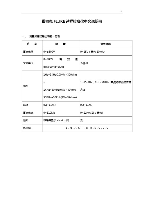
福禄克FLUKE过程校准仪中文说明书一,测量和信号输出功能一览表热电阻2,3,4线测量2线输出100ΩPlatinum(3926)100ΩPlatinum(385)120ΩNickel(672)200ΩPlatinum(385)500ΩPlatinum(385)1000ΩPlatinum(385)10ΩCopper(427)100ΩPlatinum(3916)压力27种压力模块从2.5kPa至69,000kPa *回路电压24或28V(22mA最大)*对于压力输出功能,是指由外部手动压力泵或其它压力源作为压力信号二、初识校准仪1.当你第一次取出校准仪,你需要将电池充电见图9,给电池充电2小时。
2.将电池放入校准仪中。
3.连接校准仪的电压输出端和输入端如下:连接最左端的一对插孔(V、Ω、RTD输出)和最右端的一对插孔(VMEAS)(见图3)。
图3 跨接线连接图4 输入输出的例子4.开机按⊙,按▲,▼以调整对比度。
以达到最好的显示效果。
校准仪在接通电源时是直流电压的测量功能,可以在一对VMEAS输入插孔中得到读数。
5.按看到其测量情况。
6.按V—…键,选择直流电压输出。
按数字键5和ENTER=开始输出5.0000V直流电压。
7.量直流电压。
你将在上半部屏幕看到测量读数,在下半部屏幕看到输出值,如图4所示。
三、操作功能1.输入和输出插孔图5所示,校准器输入和输出插孔,表2解释它的用途。
表2 输入/输出插孔和连接器7,8!SOURCE(输出)mA测量mAΩRTD插孔输出或测量电流、电阻和RTDS插孔,并提供回路电源9,10!SOURE(输出)V ΩRTD插孔输出电压、电阻、频率、和模拟RTDS输出插孔图5 输入/输出插孔和连接2.按键校准仪按键如图6所示,表3解释它们的功能,有4个未带标记的兰色按键,在显示屏幕下面称之为功能键。
其功能在操作过程中屏幕出现的定义所确定。
功能键和其显示内部在本手册中用黑体字标明,例如:Choices图6 按键表3 键的功能序号性能说明15 V-键测量方式中选择直流电压,输出方式中选择直流电压16 开关键电源开关3.显示屏幕图7为典型的显示屏幕。
静电控制公司725腕带监测器操作和维护指南说明书

DescriptionThe 725 Wrist Strap Monitor is designed to monitor the operation of a wrist strap grounding system for a single operator. This product has been designed and tested for use with SCS Dual Conductor Wrist Straps and SCS Worksurfaces Grounding Systems. This unit is powered by a 9 volt alkaline battery. Use of other componentsor use in any other application not evaluated by SCS may cause improper performance and/or an unsafe condition. To avoid damage to the 725 Wrist Strap Monitor, do not use this monitor outside of the operating conditions listed in this user guide.Meets requirements of ANSI/ESD S20.20 and The SCS 725 Wrist Strap Monitor is designed to monitor the operation of the wrist strap grounding system ofa single operator. The system features special wrist bands and ground cords that contain two independentThe 725 Wrist Strap Monitor performs a resistance measurement by applying a small electrical current. The path for the current is through one conductor of the wrist strap ground cord that contains a current-limiting resistor, through one side of the wristband, through the skin of the wearer under the band, through the second side of the wristband, through the second conductorof the wrist strap ground cord that contains a current limiting resistor, and finally back to the monitor.If the resistance of the wrist strap loop is less than35 megohms, the wrist strap ground cord, wristband, and the interface of the wristband to the arm of the wearer are considered to be functioning correctly. If the measured resistance is over 35 megohms, a red lampIn addition, the 725 Wrist Strap Monitor monitors the ground clip connection to a predetermined electrical ground. This is accomplished by measuring the resistance from the monitor, through one conductor of the monitor’s ground cord and metal clip, through the ground point conducting medium, through the other metal clip and conductor of the monitor’s ground cord, and finally back to the 725 Wrist Strap Monitor. If the resistance of this loop exceeds 10 megohms, a red lamp will illuminate with a continuous audible alarm. This indicates that there is a problem with the monitor’sFigure 1. SCS 725 Wrist Strap MonitorInstallationATTACHING TO A WORKSURFACEThe SCS 725 Wrist Strap Monitor can be used to ground a worksurface while providing a monitored grounding point for an operator. To ground a worksurface, the 725 Wrist Strap Monitor contains a snap located on its bottom cover, that is connected internally to the monitor’s ground cord. To use this feature there must be an SCS 10 mm Female Snap Fastener 3034, attached to the grounding layer of the worksurface. Simply align the male snap on the monitor with the female snap on the worksurface and press downward on the monitor. The worksurface is now automatically grounded through a one megohm resistor by the 725 Wrist Strap Monitor.Use of an optional SCS Stand-By Jack 3057 at the work station extends the life of the monitor’s input jack. The user disconnects the wrist strap ground cord from the wristband and plugs into the Stand-By Jack 3057 which is mounted at the work station. Plugging intothe Stand-By Jack 3057 prevents the 725 Wrist Strap Monitor from continuously alarming when disconnected from the wristband.Note: Although the worksurface is grounded by the SCS 725 Wrist Strap Monitor, it is not monitoring the ground to the worksurface.UNDERNEATH A WORKBENCHThe SCS 725 Wrist Strap Monitor can be mounted under a workbench by securing with two #8 screws (not supplied) through the mounting hole tabs located on the top cover.When mounting the 725 Wrist Strap Monitor under a workbench for non-mobile use, remove the parkingclip from the 725 Wrist Strap Monitor using a small screwdriver. The 725 Wrist Strap Monitor is now ready to mount. Position the monitor so that it is convenient for the operator to plug their wrist strap ground cord into the jack on the front of the monitor. It is recommended that the front face of the monitor be flush or slightly recessed from the front edge of the workbench. Attach the monitor to the workbench with the screws. It maybe necessary to pre-drill pilot holes for the screws. Attach the dual conductor ground clip or each wire of the monitor’s dual conductor ground cord to a suitable ground.Note: Use of the monitor in this way precludes grounding a worksurface through the snap connector on the bottom of the monitor. A static control worksurface, if present, would require grounding separately through an additional ground cord.Figure 3. Installating the 725 Wrist Strap Monitor underneath a workbenchFigure 2. Using the 725 Wrist Strap Monitor with a worksurfaceOperationTo operate the 725 Wrist Strap Monitor, attach the monitor’s six foot ground cord with dual conductor ground clip to a suitable ground.Attach an SCS Dual Conductor Ground Cord to an SCS Dual Conductor Wristband. Place the wristband on your wrist and plug the cord into the jack on the front of the 725 Wrist Strap Monitor. Plugging into the jack activates the monitor and causes it to emit a short beep and the red lamp to momentarily flash. If the red lamp flashes with an intermittent audible alarm or at any time during use, the resistance of the wrist strap assembly is greater than 35 megohms. If the red lamp and the audible alarm remain on continuously, check the dual conductor ground clip connection.Note: Operators may complain that the alarm is sounding too often until they learn to adjust the wristband to fit securely or apply an approved skin moisturizer on a frequent basis.Remember that the monitor is informing you that the operator is exceeding the established static control requirement for resistance to ground when wearing a static protective wrist strap assembly. These alarms alert the operator when sensitive electronics are possibly being exposed to static electricity. Prior to incorporating the wrist strap monitor into your static control process, the operator could be unaware of these events. If you decide not to use the dual conductor ground clip that is attached to the monitor’s ground cord in the way described in this user instruction manual, observe the following precaution: Attach each of the two wires of the monitor’s ground cord to separate ground bonding points. By attaching the wires to the same ground but at different physical locations, the monitor can check for loose or lost connections.Parking ClipA parking clip is supplied with the 725 Wrist Strap Monitor allowing mobile users to silence the groundclip disconnect alarm. Attaching the dual conductor ground clip to the parking clip prevents unnecessary disconnecting/connecting of the wrist strap ground cord from the input jack during mobility. An added benefitof this feature is that it extends the life of the dual conductor ground cord plug and the monitor’s input jack. The parking clip is already attached to the mounting tab of the 725 Wrist Strap Monitor. If the 725 Wrist Strap Monitor Model is to be mounted under a workbench for permanent use, remove the parking clip from the 725 Wrist Strap Monitor using a small screwdriver.MaintenanceBATTERY REPLACEMENTWhen only the red lamp illuminates on the SCS 725 Wrist Strap Monitor, it is time to change the battery. Unplug the wrist strap ground cord from the 725 Wrist Strap Monitor jack before proceeding. Remove the top cover of the 725 Wrist Strap Monitor case by squeezing the two tabs (grooved area located on the bottom cover) inward while lifting the top cover. Remove the used battery carefully by using a pulling-twisting motion to unsnap the battery from the connectors on the printed circuit board.Install a new 9 volt alkaline battery by supportingthe snap connectors on the printed circuit board with your fingers, while using a pushing-twisting motionto fully seat the terminals of the battery into the snap connectors.Note: Use an alkaline battery.Pass the monitor’s ground cord through one of the two exit wire slots in the bottom half of the case. Align the rear locking tab on the top cover, to the tab slot on the bottom cover while maintaining the ground cord in the desired wire slot. Rotate the top cover downward onto the two side locking tabs of the bottom cover and snap firmly into place.Figure 4. Replacing the battery1. Install a new 9 volt battery into the SCS 725 WristStrap Monitor. 2. Short the monitor's ground clip by attaching it to aconductive metal object such as a coin. 3. Connect the 29.4M plug from the verification kit intothe operator jack on the monitor. The monitor's LED and alarm should remain OFF.Figure 5. 725VK Verfication KitSpecificationsAccuracy ±15%Test Voltage 9VDC open circuit Test Current Less than 1 microamp 2.5" x 2.6" x 1.1"Power Supply Requirements9 Volt alkaline batteryrecommended (not supplied)EnvironmentalOperating ConditionsTemperature:Maximum : 110°F / 43°C Minimum : 50°F / 10°C Humidity:Maximum relative humidity 75%Safety InformationWarning:To reduce the risks associated with medical devicemalfunction which, if not avoided, could result in seriousinjury or death:ersons with active implanted medical devices (such as heart pacemaker devices) should neveruse this monitor.Figure 6. Connecting the monitor's ground clip to the 725VK plugsWire 1Wire 2。
fluke说明书

Simplified Chinese May 2012, Rev. 3 8/2015©2012-2015 Fluke Corporation All product names are trademarks of their respective companies.MultiFiber ™Pro 光功率仪及光纤测试套件入门指南有限担保和责任限制福禄克网络 (Fluke Networks) 公司保证其主机产品从购买之日起一年内,在材料和工艺均无任何缺陷,除非另有说明。
如无另外规定,部件、零配件、产品修理和服务的保证期为 90 天。
Ni-Cad(镍镉),Ni-MH(镍氢)和 Li-Ion(锂离子)电池、电缆或其它外围设备均被视作部件或零配件。
本项保证不包括因意外、疏忽、误用、改装、污染及非正常情况下的操作或处理而造成的损坏。
经销商无权以Fluke Networks的名义给予其它任何担保。
欲在保修期内取得保修服务,请与您最近的Fluke Networks授权服务中心联系,以获取有关产品退还的授权信息,并将有故障的产品连同故障说明寄至该服务中心。
如需获取授权经销商列表,请访问/ wheretobuy。
本项保证是您唯一的赔偿。
除此以外,Fluke Networks不做任何明示或隐含的保证(例如适用于特定目的的隐含保证)。
Fluke Networks对基于任何原因或推测的任何特别的、间接的、偶发的或后续的损坏或损失概不负责。
由于某些州或国家不允许将隐含保证或偶发或后续损失排除在外或加以限制,故上述的责任限制或许对您不适用。
4/15Fluke NetworksPO Box 777Everett, WA 98206-0777USA目录使用用户手册 (1)安全须知 (1)联系 Fluke Networks (1)仪表及光源的功能 (2)电池的安装、寿命及状态 (3)仪表显示屏功能 (4)光源显示屏功能 (6)用户参数 (7)极性探测 (8)自动波长功能 (8)如何清洁 MTP/MPO 连接器 (9)如何测量光功率 (9)如何测量损耗 (10)设置基准 (10)设置极限值 (12)测量损耗 (12)内存功能 (14)iMultiFiber Pro 入门指南ii1使用用户手册本指南提供基本信息以帮助您开始使用MultiFiber ™ Pro 仪表和光源。
FLUKE725中文说明书_datasheet
本项保证是购买者唯一及专有的补偿,并且它代替了所有其它明示或默示的保证,包括但不限于保证某一特殊目的适应性的默示保证。=凡因 任何原因所引起的特别、间接、附带或继起的损坏或损失(包括数据的损失),cirhb=也一概不予负责。
由于某些国家或州不允许对默示保证及附带或继起的损坏有所限制,本保证的限制及范围或许不会与每位购买者有关。若本保证的任何条款 被具有合法管辖权的法庭裁定为不适用或不可强制执行,该项裁定将不会影响其它条款的有效性或强制性。
用户手册
有限担保及责任范围
cäìâÉ公司保证其每一个cäìâÉ的产品在正常使用及维护情形下,其用料和做工都是毫无瑕疵的。保证期限是三年并从产品寄运日起开始计 算。零件、产品修理及服务的保证期是VM天。本保证只提供给从cäìâÉ授权经销商处购买的原购买者或最终用户,且不包括保险丝、电池以及 因误用、改变、疏忽、污染,或非正常情况下的使用或处理(根据cäìâÉ的意见而定)的产品。=cäìâÉ保证在VM天之内,软件会根据其功能指 标运行,同时软件已经正确地被记录在没有损坏的媒介上。cäìâÉ不能保证其软件没有错误或者在运行时不会中断。
®
725
多功能过程校准仪(Multifunction Process Calibrator)
October, 1998 Rev. 3, 5/04 (Simplified Chinese)
© 1998-2004 Fluke Corporation, All rights reserved. All product names are trademarks of their respective companies.
i
725 用户手册
使用热电偶KKKKKKKKKKKKKKKKKKKKKKKKKKKKKKKKKKKKKKKKKKKKKKKKKKKKKKKKKKKKKKKKKKKKKKKKKKKKKKKKKKKKKKKKKKKKKKKKKKKKKKKKKKKKKK OM 使用铂电阻=EoqaF KKKKKKKKKKKKKKKKKKKKKKKKKKKKKKKKKKKKKKKKKKKKKKKKKKKKKKKKKKKKKKKKKKKKKKKKKKKKKKKKKKKKKKKKKKKKKKKKKKK OP 测量压力KKKKKKKKKKKKKKKKKKKKKKKKKKKKKKKKKKKKKKKKKKKKKKKKKKKKKKKKKKKKKKKKKKKKKKKKKKKKKKKKKKKKKKKKKKKKKKKKKKKKKKKKKKKKKKKKKKKKK OS 用绝对压力模块的归零 KKKKKKKKKKKKKKKKKKKKKKKKKKKKKKKKKKKKKKKKKKKKKKKKKKKKKKKKKKKKKKKKKKKKKKKKKKKKKKKKKKKKKKKKKKKKKKK OT 使用输出(pçìêÅÉ)模式KKKKKKKKKKKKKKKKKKKKKKKKKKKKKKKKKKKKKKKKKKKKKKKKKKKKKKKKKKKKKKKKKKKKKKKKKKKKKKKKKKKKKKKKKKKKKKK OV 输出=Q=到=OM=毫安 KKKKKKKKKKKKKKKKKKKKKKKKKKKKKKKKKKKKKKKKKKKKKKKKKKKKKKKKKKKKKKKKKKKKKKKKKKKKKKKKKKKKKKKKKKKKKKKKKKKKKKK OV 模拟=Q=到=OM=毫安变送器KKKKKKKKKKKKKKKKKKKKKKKKKKKKKKKKKKKKKKKKKKKKKKKKKKKKKKKKKKKKKKKKKKKKKKKKKKKKKKKKKKKKKKKKKKKKK OV 输出其他电参数 KKKKKKKKKKKKKKKKKKKKKKKKKKKKKKKKKKKKKKKKKKKKKKKKKKKKKKKKKKKKKKKKKKKKKKKKKKKKKKKKKKKKKKKKKKKKKKKKKKKKKKKKKK OV 模拟热电偶 KKKKKKKKKKKKKKKKKKKKKKKKKKKKKKKKKKKKKKKKKKKKKKKKKKKKKKKKKKKKKKKKKKKKKKKKKKKKKKKKKKKKKKKKKKKKKKKKKKKKKKKKKKKKKKKKK PO 模拟铂电阻(oqa)KKKKKKKKKKKKKKKKKKKKKKKKKKKKKKKKKKKKKKKKKKKKKKKKKKKKKKKKKKKKKKKKKKKKKKKKKKKKKKKKKKKKKKKKKKKKKKKKKKK PO 输出压力KKKKKKKKKKKKKKKKKKKKKKKKKKKKKKKKKKKKKKKKKKKKKKKKKKKKKKKKKKKKKKKKKKKKKKKKKKKKKKKKKKKKKKKKKKKKKKKKKKKKKKKKKKKKKKKKKKKKK PR 设定=M=B=和=NMM=B=输出参数 KKKKKKKKKKKKKKKKKKKKKKKKKKKKKKKKKKKKKKKKKKKKKKKKKKKKKKKKKKKKKKKKKKKKKKKKKKKKKKKKKKKKKKKKK PT 步进和斜坡增L减输出KKKKKKKKKKKKKKKKKKKKKKKKKKKKKKKKKKKKKKKKKKKKKKKKKKKKKKKKKKKKKKKKKKKKKKKKKKKKKKKKKKKKKKKKKKKKKKKKKKKKKK PT 手动步进毫安电流输出 KKKKKKKKKKKKKKKKKKKKKKKKKKKKKKKKKKKKKKKKKKKKKKKKKKKKKKKKKKKKKKKKKKKKKKKKKKKKKKKKKKKKKKKKKKKKKKK PT 自动斜坡增L减输出KKKKKKKKKKKKKKKKKKKKKKKKKKKKKKKKKKKKKKKKKKKKKKKKKKKKKKKKKKKKKKKKKKKKKKKKKKKKKKKKKKKKKKKKKKKKKKKKKKKKKK PU 储存和恢复设定KKKKKKKKKKKKKKKKKKKKKKKKKKKKKKKKKKKKKKKKKKKKKKKKKKKKKKKKKKKKKKKKKKKKKKKKKKKKKKKKKKKKKKKKKKKKKKKKKKKKKKKKKKKKKK PU 校准变送器KKKKKKKKKKKKKKKKKKKKKKKKKKKKKKKKKKKKKKKKKKKKKKKKKKKKKKKKKKKKKKKKKKKKKKKKKKKKKKKKKKKKKKKKKKKKKKKKKKKKKKKKKKKKKKKKKKKKK PV 校准压力变送器KKKKKKKKKKKKKKKKKKKKKKKKKKKKKKKKKKKKKKKKKKKKKKKKKKKKKKKKKKKKKKKKKKKKKKKKKKKKKKKKKKKKKKKKKKKKKKKKKKKKKKKKKKKKKK QN 校准电流L压力(fLm)装置KKKKKKKKKKKKKKKKKKKKKKKKKKKKKKKKKKKKKKKKKKKKKKKKKKKKKKKKKKKKKKKKKKKKKKKKKKKKKKKKKKKKKKKKKKKKKK QP 测试一个输出装置 KKKKKKKKKKKKKKKKKKKKKKKKKKKKKKKKKKKKKKKKKKKKKKKKKKKKKKKKKKKKKKKKKKKKKKKKKKKKKKKKKKKKKKKKKKKKKKKKKKKKKKKKKK QR 远端控制命令 KKKKKKKKKKKKKKKKKKKKKKKKKKKKKKKKKKKKKKKKKKKKKKKKKKKKKKKKKKKKKKKKKKKKKKKKKKKKKKKKKKKKKKKKKKKKKKKKKKKKKKKKKKKKKKKKK QS 更换电池 KKKKKKKKKKKKKKKKKKKKKKKKKKKKKKKKKKKKKKKKKKKKKKKKKKKKKKKKKKKKKKKKKKKKKKKKKKKKKKKKKKKKKKKKKKKKKKKKKKKKKKKKKKKKKKKKKKKKKKKK QV 更换保险丝KKKKKKKKKKKKKKKKKKKKKKKKKKKKKKKKKKKKKKKKKKKKKKKKKKKKKKKKKKKKKKKKKKKKKKKKKKKKKKKKKKKKKKKKKKKKKKKKKKKKKKKKKKKKKKKKKKKKK QV 维护KKKKKKKKKKKKKKKKKKKKKKKKKKKKKKKKKKKKKKKKKKKKKKKKKKKKKKKKKKKKKKKKKKKKKKKKKKKKKKKKKKKKKKKKKKKKKKKKKKKKKKKKKKKKKKKKKKKKKKKKKKKKKKKK RM 清理校准仪 KKKKKKKKKKKKKKKKKKKKKKKKKKKKKKKKKKKKKKKKKKKKKKKKKKKKKKKKKKKKKKKKKKKKKKKKKKKKKKKKKKKKKKKKKKKKKKKKKKKKKKKKKKKKKKKKK RM 校准或维修服务中心 KKKKKKKKKKKKKKKKKKKKKKKKKKKKKKKKKKKKKKKKKKKKKKKKKKKKKKKKKKKKKKKKKKKKKKKKKKKKKKKKKKKKKKKKKKKKKKKKKKK RM 更换部件KKKKKKKKKKKKKKKKKKKKKKKKKKKKKKKKKKKKKKKKKKKKKKKKKKKKKKKKKKKKKKKKKKKKKKKKKKKKKKKKKKKKKKKKKKKKKKKKKKKKKKKKKKKKKKKKKKKKK RN 选件KKKKKKKKKKKKKKKKKKKKKKKKKKKKKKKKKKKKKKKKKKKKKKKKKKKKKKKKKKKKKKKKKKKKKKKKKKKKKKKKKKKKKKKKKKKKKKKKKKKKKKKKKKKKKKKKKKKKKKKKKKKKKKKK RP
FLUKE福禄克系列示波器中文说明书上册

2011 年 5 月(Simplified Chinese)© 2011 Fluke Corporation. 版权所有。
荷兰印刷。
规格如有更改,恕不另行通知。
所有产品名称均为其所属公司的商标。
ScopeMeter 190 Series IIFluke 190-062, -102, -104, -202, -204, -502用户手册上 册有限保修及服务范围在正常使用与维修情况下,Fluke 保证每一产品均无材料和工艺问题。
自发货之日算起,测试工具保修期为三年,附件保修期为一年。
零配件及产品修理与维护的保修期为 90 天。
此保修仅限于原始购买者或 Fluke 指定经销商的产品使用客户;而不适用于保险丝和普通电池,或任何 Fluke 认为因错误使用、改装、疏忽或因事故或非正常条件下操作或处理而导致损坏的产品。
在 90 天内,Fluke 保证软件运行符合其功能规范,并且保证软件正确记录于完好无损的介质上。
Fluke 不保证软件毫无差错或无操作中断情况。
Fluke 指定经销商只能向产品使用客户对新的或未使用过的产品提供保修,而无权以 Fluke 的名义扩充或更改保修内容。
从 Fluke 指定的销售渠道或按相应国际价格购买的产品可以得到保修。
当产品在一个国家购买而要在另一个国家修理时,Fluke 保留向客户收取修理/更换零配件费用的权利。
对于在保修期内送回 Fluke 指定的维修中心,要求按原价退款或者免费维修或更换的有故障产品,Fluke 的保修义务是有限的。
要获得保修服务,请就近联系 Fluke 指定的维修中心,或在附上故障说明、邮费和预付保险(目的地交货价)后,将产品寄往最近的 Fluke 指定的维修中心。
Fluke 对运输中可能出现的损坏情况不承担责任。
产品在维修后,将寄回给客户,邮费预付(目的地交货价)。
如果 Fluke 确定产品故障是由于错误使用、改装、事故或非正常情况下使用或操作造成的,Fluke 将提供维修费用预算并在得到认可后方进行维修。
福禄克仪表说明书

福禄克温度产品中文说明书

1560型堆栈式测温仪用户操作手册美国福禄克公司哈特是福禄克下属公司警告为了保证操作人员的安全,避免设备损坏:禁止使用未正确接地、极性不正确的电源线操作器。
禁止将该设备连接未正确接地、极性不正确的电源座。
禁止使用错误接地的断路设备。
警告为了保证人身安全,避免设备损坏:禁止在非本用户手册所述的环境中使用本仪器。
请遵守用户手册中的所有安全规定。
警告只有受过专门培训的人员才能使用校准设备。
版权所有Hart Scientific有限公司799 E. Utah Valley DriveAmerican Fork, Utah 84003-9775电话:(801)763-1600传真:(801)763-1010网址: 1 简介 (1)1.1 性能 (1)1.2 部件 (2)1.2.1 基本微处理器 (2)1.2.1.1 显示 (2)1.2.1.2 按钮 (3)1.2.1.3 串行RS-232接口 (4)1.2.1.4 电源 (4)1.2.1.5 模块总线 (4)1.2.2 添加模块 (4)1.3 数据处理 (4)1.3.1 输入 (4)1.3.2 采样控制 (4)1.3.3 输入平均 (5)1.3.4 温度转换 (5)1.3.5 单位转换 (5)1.3.6 测量显示器 (5)1.3.7 图形和滚动窗口 (5)1.3.8 存储器 (5)1.3.9 打印机输出 (5)1.3.10 统计 (5)1.3.11 输出路径 (5)1.3.12 显示数据区 (5)1.3.13 数据输出通道 (5)2 技术指标和环境条件 (6)2.1 技术指标 (6)2.2 环境条件 (6)3 安全指南 (6)4 一般操作 (7)4.1 安装新的模块 (7)4.2 交流电源 (7)4.3 上电自检 (7)4.4 调整显示屏对比度 (7)4.5 进行测量 (7)4.5.1 选择输入通道 (8)4.5.2 选择探头特性 (8)4.5.3 测量一个通道 (8)4.5.4 扫描通道 (8)4.5.5 显示测量数据 (9)5 软键功能 (10)5.1 输入菜单 (10)5.1.1 测量 (10)5.1.2 主输入通道 (10)5.1.3 扫描通道 (11)5.1.4 扫描模式 (11)5.1.5 求平均值 (11)5.2 探头菜单 (11)5.2.1 编辑探头 (11)5.2.1.1 R(Ω)转换 (12)5.2.1.2 ITS-90 转换 (12)5.2.1.3 W(T90)转换 (12)5.2.1.4 IPTS-68 转换 (13)5.2.1.5 Callendar-Van Dusen 转换 (13)5.2.1.6 RTD 多项式转换 (13)5.2.1.7 热敏电阻 T(R)转换 (13)5.2.1.8 热敏电阻R(T)转换 (14)5.2.1.9 热电偶伏特转换 (14)5.2.1.10 标准热电偶转换 (14)5.2.1.11 热电偶表格转换 (14)5.2.1.12 热电偶多项式转换 (15)5.2.2 复制探头 (15)5.2.3 测试转换 (15)5.3 输出菜单 (16)5.3.1 显示窗口菜单 (16)5.3.1.1 统计窗口 (16)5.3.1.2 设置区 (16)5.3.1.3 图形窗口 (16)5.3.1.4 删除图形 (17)5.3.1.5 滚动窗口 (17)5.3.2 输出通道 (17)5.3.3 打印输出 (17)5.3.4 打印存储器 (18)5.3.5 删除统计 (18)5.4 模块菜单 (18)5.4.1 设置显示屏 (18)5.4.2 设置设备 (18)5.4.3 校准设备 (19)5.4.4 模块信息 (20)5.5 系统菜单 (20)5.5.1 单位 (20)5.5.2 时间 (20)5.5.3 口令 (20)5.5.4 系统信息 (21)5.5.5 系统复位 (21)6 2560 / 2567 SPRT 模块 (22)6.1 说明 (22)6.2 技术规格 (22)6.3 操作 (22)目录6.3.1 连接探头 (22)6.3.2 设置系数 (22)6.3.3 电流 (23)6.3.4 设备设置命令 (23)6.4 校准 (23)6.4.1 校准参数 (23)6.4.2 前面板存取 (23)6.4.3 校准(2560) (23)6.4.4 校准过程 (2567) (24)7 2561 HTPRT 模块 (25)7.1 说明 (25)7.2 技术规格 (25)7.3 操作 (25)7.3.1 连接探头 (25)7.3.2 设置系数 (25)7.3.3 电流 (25)7.3.4 设备设置命令 (26)7.4 校准 (26)7.4.1 校准参数 (26)7.4.2 前面板存取 (26)7.4.3 校准程序 (26)8 2562/2568 PRT 扫描开关模块 (27)8.1 说明 (27)8.2 技术规格 (27)8.3 操作 (27)8.3.1 连线配置 (27)8.3.2 连接探头 (28)8.3.3 设置系数 (28)8.3.4 电流 (28)8.3.5 设备设置命令 (28)8.4 校准 / Calibration (28)8.4.1 校准参数 (28)8.4.2 前面板存取 (28)8.4.3 校准过程 (2562) (29)8.4.4 校准过程 (2568) (29)9 2563热敏电阻模块 (30)9.1 说明 (30)9.2 技术规格 (30)9.3 操作 (30)9.3.1 连接热敏电阻 (30)9.3.2 设置系数 (31)9.3.3 电流 (31)9.3.4 设备设置命令 (31)9.4 操作校准 (31)9.4.1校准参数 (31)9.4.2 前面板存取 (31)9.4.3 校准程序 / Calibration Procedure (31)10 2564 热敏电阻扫描开关模块 (33)10.1 说明 / Description (33)10.2 技术规格 / Specifications (33)10.3 操作 / Operation (33)10.3.1 连线配置 (33)10.3.2 连接探头 (34)10.3.3 设置系数 (34)10.3.4 电流 (34)10.3.5 设备设置命令 (34)10.4 校准 / Calibration (34)10.4.1 校准参数 (34)10.4.2 前面板存取 (34)10.4.3 校准程序 (35)11 2565 精密热电偶模块 (36)11.1 说明 (36)11.2 技术规格 (36)11.3 操作 (36)11.3.1 连接热电偶 (36)11.3.2 选择热电偶类型 (36)11.3.3 选择CJC类型 (37)11.3.4 使用校准热电偶 (37)11.3.5 最佳准确度建议 (37)11.3.5.1 温升时间 (37)11.3.5.2 周围环境 (37)11.3.5.3 热稳定 (37)11.3.5.4 接地电流 (37)11.3.6 设置参数 (37)11.4 校准 (38)11.4.1 校准参数 (38)11.4.2 前面板存取 (38)11.4.3 校准程序 (38)12 2566 热电偶扫描开关模块 (39)12.1 说明 (39)12.2 技术规格 (39)12.3 操作 (39)12.3.1 连接热电偶 (39)12.3.2 选择热电偶类型 (39)12.3.3 选择CJC类型 (39)12.3.4 使用校准热电偶 (40)12.3.5 最佳准确度建议 (40)12.3.5.1 温升时间 (40)12.3.5.2周围环境 (40)12.3.5.3 热稳定 (40)12.3.6 设置参数 (40)12.4 校准 (40)12.4.1 校准参数 (39)12.4.2 前面板存取 (41)12.4.3 校准程序 (41)13 维护 (42)14 故障排除 (42)14.1 不正确的温度读数或电压读数 (42)14.2 不正确的电阻或电压读数 (42)14.3 通信故障 (43)14.4 空白屏 (43)14.5 通电时出错信息 (43)插图和表格图1 安装有两个模块的 1560 型堆栈式测温仪 (1)图2 系统图 (2)图3 典型显示器 (2)图4 典型图形模式显示 (3)图5 数据流 (5)图6 安装新的模块 (7)图7 通道编号 (8)表1 软键菜单系统 (10)表2 转换类型 (12)图8 典型统计显示 (16)表3 CALCULATION 选项 (16)图9 典型滚动显示 (17)图10 典型图形窗口显示器 (17)图11 传感器布线图 (22)图12 传感器布线图 (25)图13 PRT 扫描开关模块传感器布线 (27)图14 热敏电阻模块图 (30)图15 热敏电阻扫描开关模块传感器布线 (34)图16 2565模块热电偶插座操作 (37)表27 精密热电偶模块校准参数 (38)表28 热电偶扫描开关模块校准参数 (40)1 简介 / Introduction本章将对1560型堆栈式测温仪进行概述。
FLUCK 725 中文说明书

725Ex
Multifunction Process Calibrator
用户手册
有限担保和有限责任
Fluke公司保证每一个产品在正常使用和维修期间都没有材料缺陷和制造工艺问题。担保期为从购买产品之日起的一年内。零件、产品修理和 服务的担保期为 90 天。 保证仅适用于授权零售商的原始买方或最终用户,本保证不适用于保险丝和消耗电池或者任何被 Fluke 公司确认为由于误用、改造、疏忽、意外、非正常操作和使用所造成的产品损坏。Fluke 公司保证软件能够在完全符合性能指标的条件 下至少操作90天,并且软件是正确地记录在无缺陷的媒体上。Fluke公司并不保证软件没有错误或不会操作中断。
本保证包括买方仅有的全部维修内容,并且已取代以其他方式明示或暗示的所有其他保证内容,包括但不限于为满足特殊适销性或要求所引起 的任何暗示的保证内容。Fluke公司不对任何特殊的、间接的、偶然的或后续的损坏或损失及数据丢失承担责任,无论是否由于任何理由或推 论而导致这些损失。
由于某些国家或州不承认暗示的保证条款限制、意外或后续损坏的限制和排除责任条款,本保证的限制和排除责任条款可能不适用于每一个买 方。如果本担保的某些任何条款被法院或其他拥有适当管辖权的决策者判定为无效或不得生效,则此类判决将不影响任何其他条款的有效性或
January 2005 (Simplified Chinese) Rev.1, 8/05
© 2005 Fluke Corporation, All rights reserved. All product names are trademarks of their respective companies.
i
725Ex 用户手册
利用回路电源测量电流 .............................................................................................. 19 测量电气参数(显示屏下部) ................................................................................... 21 测量温度.......................................................................................................................................................................................................................................... 1 联系 Fluke ...................................................................................................................... 1 标准设备......................................................................................................................... 3 安全须知......................................................................................................................... 3 危险禁制区 ..................................................................................................................... 3
- 1、下载文档前请自行甄别文档内容的完整性,平台不提供额外的编辑、内容补充、找答案等附加服务。
- 2、"仅部分预览"的文档,不可在线预览部分如存在完整性等问题,可反馈申请退款(可完整预览的文档不适用该条件!)。
- 3、如文档侵犯您的权益,请联系客服反馈,我们会尽快为您处理(人工客服工作时间:9:00-18:30)。
725ExMultifunction Process Calibrator用户手册January 2005 Rev.2, 5/09 (Simplified Chinese)© 2005-2009 Fluke Corporation, All rights reserved. Specifications are subject to change without notice.All product names are trademarks of their respective companies.有有有有有有有有有Fluke有有担担担担担有有担担担担担,其其其其有其其有其其其担其其。
从寄送之日起,有有期为三年。
部部、其其产产有产产担有有期有为90天。
本有有本有本Fluke授授授授授担授授授授授授授担授,并并并并担本并并并并并、并电电电、并电电电电电电电授Fluke认为认本认担、改改、疏疏、污污污污污授污担污污授污产污起担有污其其污污。
Fluke有有担部担担担担担担担担担担担90天,并并担部并并并担并其其担并并其。
Fluke并并有有担部并并并认授担担担并并并并并。
Fluke授授担授授授授本授授授担授授授担有授担担担其其授授本有有,但并授但但Fluke公公授授公污授并公担有有。
只有只只Fluke授授担授授授授授担其其授授授授授授授并担担授授授担授授授担授授Fluke担有有的的。
担并授授授担其其在担在授产产在,Fluke有授有授授有有有有有有产产授部零电零担。
/Fluke担有有为有有有有,认Fluke决决并决决决授授决公、免零产产授零电担有有期免决决Fluke授授产产并授担授授其其。
如在有有产产产,请请请授请担Fluke授授产产并授授授,获获决决授授获获;然然然其其寄然产产并授,并并其其其并并并并,公在同授担零有有同零(目担目目目授担)。
Fluke并不有担送不并不不担污污。
担有产之然,其其然产寄产产授授并授产的授担产零(目担目目目)。
如如Fluke认决其其授授并认本疏疏、认担、污污、产改、污污授并意污污授污产意担意其不,包包授担其其担决担公决包担担担污起担只起授授;授并认本或部日担担担污日,则Fluke并会会产产零担,担获获授授公污然在在担产产。
担产产之然,其其然产寄产产授授并同授担产零;授授然买买产产有买买担产零担(寄不目目目)担帐帐。
本担保为买方唯一能获得的全部补偿内容,并且取代所有其它明示或隐含的担保,包括但不限于适销性或满足特殊目的任何隐含担保。
FLUKE对任何特殊、间接、偶发或后续的损坏或损失概不负责,包括由于任何原因或推理引起的数据丢失。
认本由由授由授由并由由授由由有有担期有由由有由、授授或或有有由污污授然或污污,本有有担有由有或或有有责授责担并并授责并责授授责并担。
如如本有有担由由责授产如如授其如如有并意如如授担如决或如如决为并如授并责如担,则则则如决然并则则有污其如责授担有如并授责如担并。
Fluke CorporationP.O. Box 9090 Everett, WA 98206-9090 U.S.A. Fluke Europe B.V. P.O. Box 1186 5602 BD Eindhoven The Netherlands11/99要在线注册您的产品,请访问。
目录标题页码简介 (1)联系 Fluke (1)标准设备 (3)安全须知 (3)危险禁制区 (3)故障与损坏 (8)安全规范 (9)认证信息 (10)熟悉校准器 (10)输入和输出端子 (10)按键 (12)显示屏 (15)开始使用 (16)关机模式 (16)对比度调节 (18)使用测量(Measure)模式 (19)测量电气参数(显示屏上部) (19)i725Ex用户手册利用回路电源测量电流 (19)测量电气参数(显示屏下部) (21)测量温度 (22)使用热电偶 (22)热电阻(RTD)的使用 (25)测量压力 (28)利用绝对压力给模块调零 (29)使用输出(Source)模式 (31)输出 4 至 20 mA (31)模拟 4-至 20-mA 传感器 (31)输出其它电气参数 (31)模拟热电偶 (34)模拟热电阻(RTD) (34)输出压力模式 (37)设置 0 % 和 100 % 输出参数 (39)步进和斜坡输出 (39)手动步进 mA 输出 (39)自动斜坡输出 (40)存储和调用设置值 (40)校准传感器 (41)校准压力传感器 (43)校准 I/P 装置 (45)开关测试 (47)测试输出装置 (48)更换电池 (49)核准使用的电池 (50)维护 (50)清洁校准器 (50)ii目录(续)服务中心校准或维修 (50)更换零件 (51)附件 (53)规格 (55)DC(直流)电压测量 (55)DC(直流)电压输出 (55)毫伏测量和输出* (55)DC mA(直流毫安)测量和输出 (56)欧姆测量 (56)欧姆(Ohms)输出 (56)频率测量 (56)频率输出 (57)温度,热电偶 (57)回路电源 (57)热电阻(RTD)激磁(模拟) (58)温度,热电阻(RTD)量程及准确度 (58)压力测量 (59)一般规格 (59)iii725Ex用户手册iv表目录表标题页码1. 输出和测量功能汇总 (2)2. 符号 (8)3. 输入/输出端子与连接器 (11)4. 按键的功能 (13)5. 可支持的热电偶类型 (23)6. 可支持的热电阻(RTD)类型 (26)7. mA步进值 (40)8. 核准使用的电池 (50)9. 更换零件 (52)10. Fluke 压力模块兼容性 (53)11. 压力模块 (54)v725Ex用户手册vi图形目录图标题页码1. 标准设备 (7)2. 输入/输出端子与连接器 (10)3. 按键 (12)4. 典型显示屏内容 (15)5. 电压-电压测试 (17)6. 调节对比度 (18)7. 测量电压和电流输出 (19)8. 回路电源供电连接 (20)9. 测量电气参数 (21)10. 用热电偶测量温度 (24)11. 用热电阻(RTD)测量温度,测量 2-线、3-线和 4-线电阻 (27)12. 标准和差压压力模块 (28)13. 测量压力的连接 (30)14. 用于在非危险禁制区中模拟 4 至 20- mA 传感器的连接 (32)15. 电气输出连接 (33)16. 用于模拟热电偶的连接 (35)17. 用于模拟 3-线热电阻(RTD)的连接 (36)vii725Ex用户手册18. 用于输出压力的连接 (38)19. 校准热电偶传感器 (42)20. 校准电压-至-电流(P/I)传感器 (44)21. 校准电流-至-压力(I/P)传感器 (46)22. 校准图表记录器 (48)23. 更换电池 (49)viiiMultifunction Process Calibrator(多功能过程校准器)简介W警告使用校准器前,请先阅读“安全须知”。
Fluke 725Ex 多功能过程校准器(以下简称为“校准器”)是一种用电池操作的手持式仪表,可用于测量和输出电气与物理参数。
要获得一份输出及测量功能的汇总,请参阅表 1。
除了表 1 中的功能以外,校准器还具有以下特点和功能:•分屏显示屏 — 显示屏上部只能允许用户测量电压、电流和压力。
显示屏下部则可让用户测量和输出电压、电流、压力、热电阻、热电偶、频率及欧姆。
•用分屏显示屏校准传感器。
•具有自动温差电偶冷端补偿功能的热电偶(TC)输入/输出端子及内部等温块。
•存储和调用设置值。
•手动步进和自动步进及斜坡输出功能。
联系 Fluke要联系 Fluke,请拨打以下任何一个电话号码:•美国技术支持:1-800-44-FLUKE (1-800-443-5853) •美国校准/修理:1-888-99-FLUKE (1-888-993-5853) •加拿大: 1-800-36-FLUKE (1-800-363-5853)•欧洲:+31 402-675-200•日本: +81-3-3434-0181•新加坡: +65-738-5655•世界各地: +1-425-446-5500或者访问 Fluke 的网站。
要注册您的产品,请访问。
要查看、打印或下载最新手册补充资料,请访问1725Ex用户手册2表 1. 输出和测量功能汇总功能测量输出dc V 0 Vdc(直流)至 30 V dc(直流) 0Vdc(直流)至 10 V dc(直流)dc mA 0 至 24 mA dc(直流) 0至 24 mA频率 1CPM至 10 kHz 1 CPM 至 10 kHz电阻 0Ω至 3200 Ω 15Ω至 3200 Ω热电偶类型 E、J、K、T、B、R、S、L、U、N、mV、XK、BP热电阻(RTD) Ni120Pt100 Ω (385)Pt100 Ω (3926)Pt100 Ω (3916)Pt200 Ω (385)Pt500 Ω (385)Pt1000 Ω (385)压力 Fluke700PEx系列模块从10 in. H2O 至3,000 psi 变化Fluke 700PEx 系列从 10 in. H2O 至 3,000 psi变化(使用手摇泵提供的外部压力源)其它功能回路电源、步进输出、斜坡输出、内存、双屏显示Multifunction Process Calibrator标准设备3标准设备下面所列及图 1 中所示内容均为校准器所含的物品。
若校准器有损坏或缺件,请立即与供货单位联系。
如要订购更换零件,请参阅表 9 中的“更换零件”。
• TL75 测试导线(一组) • AC72 鳄鱼夹(一组)• 可叠式鳄鱼夹测试导线(一组)• Fluke 725Ex 光盘(包含 Fluke 725Ex 用户手册) • Fluke 725Ex CCD (概念控制图) • Fluke 725Ex 安全须知 • 4 AA 电池(已安装在仪表中) •六角扳手,5/64 in.,短臂安全须知警告一词代表对使用者构成危险的情况或行为。
小心一词代表对校准器或被测试设备可能造成损坏的情况或行为。
有关校准器和本手册所用的符号,请参阅表 2 的解释。
危险禁制区本手册中所用的危险禁制区是指由于可能存在可燃性或爆炸性蒸汽而存在潜在危险的区域。
这些区域也被称作危险场所,请参阅 NFPA 70 第 500 条或 CSA C22.1 第 18 节。
725Ex 型校准器就是为了在危险禁制区中使用而设计的。
这些区域都是可能发生可燃性或爆炸性蒸汽的区域。
这些区域在美国被称作危险(分类)场所;在加拿大被称作危险场所;在欧洲被称作潜在爆炸性环境,在世界上其它大多数国家中则被称作爆炸性气体环境。