超声波传感器用户手册
超声波传感器使用说明
超声波传感器使用说明1.电源接入:将超声波传感器的电源线与电源连接,确保电压稳定。
2.连接触发引脚和接收引脚:超声波传感器有一个触发引脚和一个接收引脚,触发引脚用于发送超声波脉冲,接收引脚用于接收反射波。
将传感器的触发引脚与控制器的IO口相连,接收引脚与控制器的IO口相连。
3.发射超声波脉冲:在控制器上设置触发引脚为高电平,保持一段时间后再下降到低电平。
高电平触发传感器发射超声波脉冲,可以通过设置触发时间来控制脉冲的持续时间,一般来说,脉冲持续时间越长,测量距离的精度越高。
4.接收反射波信号:超声波传感器发射的脉冲波会在物体上反射并返回,传感器接收到这个反射波信号后,触发引脚会发出一个低电平信号。
通过测量这个低电平信号的持续时间,可以计算出目标物体与传感器之间的距离。
一般可以通过控制器的计时器功能来测量这个时间。
5.计算距离:利用传感器发送和接收的时间差,结合超声波在空气中的传播速度,可以精确计算出目标物体与传感器之间的距离。
一般计算公式为:距离=时间差×速度,其中速度一般取340m/s。
6.转换为实际距离:有些超声波传感器会输出一个毫秒级的时间差值,需要根据传感器的数据手册来进行换算,将时间差转换为实际距离。
需要注意的是,超声波传感器对目标物体的性质有一定要求,例如传感器对于反射率较低的物体,如软质材料、液体、吸声材料等,测量距离的精度可能会降低。
此外,超声波传感器也有一定的应用注意事项,比如需要避免在多传感器密集布置的环境下使用,避免互相的干扰;要避免在含有较多尘埃、雾霾等粒子的环境中使用,以免影响测量结果;还要避免在强电磁辐射的环境下使用,以防止电磁辐射对传感器的工作性能产生干扰。
总结起来,超声波传感器的使用非常简单,只需连接电源、触发引脚和接收引脚、发送超声波脉冲,然后通过计算时间差来获取目标物体与传感器之间的距离。
在应用中,还要注意目标物体的特性和环境的影响,以获取准确的测量结果。
超声波传感器的使用说明书

超声波传感器的使用说明书
一、产品概述
超声波传感器是一种利用超声波原理进行测距的装置,具有测量准确、反应速度快、抗干扰能力强等特点。
本产品适用于各种需要进行距离测量的场合,如机器人避障、物体定位、液位监测等。
二、产品特点
1. 高精度测量:采用先进的超声波发射和接收技术,能够实现高精度的距离测量,误差率小于1%。
2. 快速反应:产品具有快速的信号处理速度和反应时间,能够在短时间内获取准确的测量结果。
3. 抗干扰能力强:采用特殊的信号处理技术,能够有效地减少电磁干扰、环境噪声等因素对测量结果的影响。
4. 易于安装:产品体积小,重量轻,易于安装和调试。
三、使用步骤
1. 安装传感器:将超声波传感器固定在需要测量的位置,确保传感器前方无遮挡物,并且传感器能够正常发射和接收超声波。
2. 连接电源:将超声波传感器的电源线连接到控制器或电源适配器上,确保电源稳定可靠。
3. 调试传感器:通过控制器或软件对超声波传感器进行参数设置和
调试,确保测量结果准确可靠。
4. 读取数据:通过控制器或软件读取超声波传感器的测量数据,根据需要进行数据处理和分析。
四、注意事项
1. 避免在高温、高湿度、高粉尘等恶劣环境下使用传感器。
2. 在安装传感器时,应避免在传感器前方放置金属等反射物,以免影响测量结果。
3. 在调试传感器时,应按照说明书上的参数进行设置,不要随意更改参数。
4. 在读取数据时,应确保连接可靠,不要随意断开连接。
超声波液位探测传感器使用手册
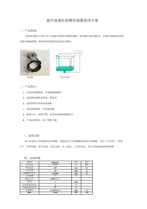
超声波液位探测传感器使用手册一、产品阐述:深圳电进联公司设计生产的超声波液位探测传感器,采用超声波穿透技术,实现对容器内的液体高度非接触探测,把液体高度值转化成电信号输出。
实物图应用示意图二、产品特点1、实现非接触探测,不接触被测液体2、实时输出液体高度值,精度高3、适用各种不同材质的液体4、适用各种材质、厚度的容器5、体积小巧,安装方便,适用各种液体探测场合6、产品品质稳定,抗干扰能力强三、适用范围本产品适用于各种液体实时探测,特别适合对不能接触液体进行的探测。
已经广泛应用于,饮料生产、家用电器、医疗设备、饮水设备、化工设备、工业自动化、各行业危险液体物品探测。
四、电器参数备注:1、5V供电,IS工作周期测试所得数据。
2、常温下IOmm厚度钢板容器,容器直径40Omm测试水所得数据。
3、常温下IOmnl厚度钢板容器测试水所得数据,H表示当前液位高度。
4、探头外壳、输出引线符合IEC61000-4-2标准。
六、接线引脚定义七、品质参数1、额定环境条件备注:a、环境温度在0-39C时,湿度最高值为90%(不凝露)b、环境温度在40-5(TC时,湿度最高为当前温度下自然界最高湿度(不凝露)2、额定电气条件八、数据输出格式1、UART通信说明注:校验和只保留累加数值的低8位;SUM=(帧头+DataH+DataD&OxOOFF=(OXFF+0X07+OXAD&OxOOFF=0XΛ7;液位值=Data,H*256+Data_L=0X07Al;转换成十进制等于1953:表示当前测量的量程值为1953亳米。
九、LED指示灯状态说明1、LED长亮:模组通电但没有探测到液体。
2、LED慢闪:模组探测到液体时,LED指示灯以每秒1次频率闪烁。
十、可靠性测试条件十一、注意事项1、产品实际应用中,液体容器所用的材质、容器的厚度会导致不同的盲区。
2、产品实际应用中,在有效探测量程内,液面晃动会导致探测数偏离。
EM310-UDL 超声波测距传感器用户手册说明书

超声波测距传感器EM310-UDL用户手册安全须知为保护产品并确保安全操作,请遵守本使用手册。
如果产品使用不当或者不按手册要求使用,本公司概不负责。
严禁拆卸和改装本产品。
请勿将产品放置在不符合工作温度、湿度等条件的环境中使用,远离冷源、热源和明火。
请勿使产品受到外部撞击或震动。
本产品不可作为计量工具使用。
为了您的设备安全,请及时修改设备默认密码(123456)。
产品符合性声明EM310-UDL系列符合CE,FCC和RoHS的基本要求和其他相关规定。
版权所有©2011-2022星纵物联保留所有权利。
如需帮助,请联系星纵物联技术支持:邮箱:*********************电话:************传真:************总部地址:厦门市集美区软件园三期C09栋深圳:深圳市南山区高新南一道TCL大厦A709文档修订记录日期版本描述2021.9.6V1.0第一版2021.12.30V1.1更新品牌Logo目录一、产品简介 (4)1.1产品介绍 (4)1.2产品亮点 (4)二、产品结构介绍 (4)2.1包装清单 (4)2.2外观概览 (5)2.3产品尺寸 (5)2.4电源按钮与指示灯 (5)三、产品配置 (6)3.1NFC配置 (6)3.2LoRaWAN®基本配置 (6)3.3常用设置 (9)3.4高级设置 (9)3.4.1校准设置 (9)3.4.2阈值设置 (10)3.5维护 (10)3.5.1升级 (10)3.5.2备份 (11)3.5.3重置 (12)四、产品安装 (12)五、数据通信协议 (13)5.1设备信息 (13)5.2传感器数据 (14)5.3下行指令 (14)一、产品简介1.1产品介绍EM310-UDL 是一款功能强大的超声波测距传感器,采用双探头设计,利用超声波测距原理,以非接触方式精准测量传感器与目标间的距离。
同时产品还内置MEMS 三轴加速度计,可用于监控设备姿态。
超声波传感器安装指南说明书

INSTALLATION GUIDEUltrasonic Sensors Series UFP and UPAFor further information please see the data sheet at /products/ultrasonic-sensorsWayCon Positionsmesstechnik GmbH would like to thank you for the trust you have placed in us and our products. This manual will make you familiar with the installation and operation of our ultrasonic sensors. Please read this manual carefully before initial operation!Unpacking and checking:Carefully lift the device out of the box by grabbing the housing. After unpacking the device, check it for any visible damage as a result of rough handling during the shipment. Check the delivery for completeness. If necessary, consult the transportation company, or contact WayCon directly.• Ultrasonic sensors may be installed in any position, as long as depositions like dust, spray mist, or condensing humidity are avoided on the sound active membrane.• It is important to avoid structure-borne sound bridges between the sensor and its holder.• In case several ultrasonic sensors are used in one application, it is important to leave sufficient distance between them. Otherwise the sensors may interact which leads to false measurement values.• By using a sound deflection angle the sound beam can be redirected, at the expense of the sensor’s maximum measurement range. A plain and hard surface should be used for the defection of the sound beam. Redirecting the sound beam with multiple sound deflection angles should be avoided.TEACHING THE ANALOG OUTPUTEvery sensor is delivered with the factory set-up (max. measurement range). The teach-in feature is designed to choose a smaller range within the nominal measuring range for optimizing the resolution and linearity. Output current, or output voltage adapt to the new range and get new characteristic curves. The two positions P1 and P2 must be taught.CharacteristicsP1 and P2 define the analog output slope.P1 determines the 0 V / 4 mA position and P2 the 10 V / 20 mA position.P1P24 mA / 0 V20 mA / 10 VPositive slope: P1 < P2P2P14 mA / 0 V20 mA / 10 VNegative slope: P2 < P1Teach-In of P1 (SP1 position)Connect Teach-In line with GND until P1 and Echo LEDs start blinking with a 2 Hz frequency (UFP-200 just yellow). Release the contact. The sensor is now in the Teach-In mode for P1: P1 LED will now blink with 1 Hz frequency (UFP-200 with ½ Hz) and the Echo LED will go back to normal function (alignment LED). There is a time window of 30 seconds to do the programming of P1. Place the target at the new position P1. Connect and release Teach-In line with GND: P1 is now programmed. Sensor returns to normal function with the new value for P1.(UFP-200 just yellow, 1 Hz). First P1 and Echo LEDs will be blinking, but it is important to wait to reach P2. The sensor is now in the Teach-In mode for P2: P2 LED blinks with 1 Hz frequency now (UFP-200 just yellow, ½ Hz). The Echo LED returns to normal function (alignment LED). There is a time window of 30 seconds to do the programming of P2. Place target at the new position P2. Contact and release the Teach-In line with GND: P2 is now programmed. Sensor returns to normal function with the new value for P2.Environmental influences:Ultrasonic sensors are made for the use in atmospheric air. Environmental Influences like rain, snow, dust or smoke have no influence on the accuracy of the measurement. However, measurements under pressure (higher that the atmospheric pressure) are not possible with ultrasound sensors.Strong wind or air turbulences may lead to instability in measurement values. A flow speed up to a few m/s is unproblematic and will have no influence on the sensor’s accuracy.Target Influences:• Liquids are excellently detectable with ultrasound. A classic application for ultrasonic sensors is level measurement. The sound beam axis however must have a maximum deviation of 3° vertically to the liquid level (no strong waves), otherwise the reflected sound will miss the sensor.• Hot Targets with high temperatures cause a thermal convection in the surrounding air. For this reason the sound beam may be strongly diverted vertically to its axis, so that the echo is weakened, or can no longer be received at all.• For convex (cylindrical and spherical) surfaces every area element has a different angle to the sound cone’s axis. The reflected cone thus diverges and the portion of the sound energy reflected to the receiver is reduced correspondingly. The maximum range decreases with the decreasing size of the cylinder (ball).• The roughness and surface structures of the object to be detected also determine the scanning capacities of the ultrasonic sensors. Surface structures that are larger than the ultrasound wavelength, as well as coarse-grained bulk materials, reflect ultrasound in a scattered manner, and are not detected optimally by the sensor under these conditions.• Hard material reflects almost all of the impulse energy from ultrasound applications in a way that makes them very easy to detect with ultrasound.• Soft material, on the other hand, absorbs almost all of the impulse energy. It is thus harder to detect with ultrasound. These materials include felt, cotton, coarse meshes, foam, etc.• Thin-walled foils behave like soft materials. To be able to use ultrasound, the foil thickness should be at least 0.01 mm.WayCon Positionsmesstechnik GmbHMehlbeerenstraße482024 Taufkirchen / GermanyThis is to certify that the productsClassification Ultrasonic SensorsSeries UFP, UPAfulfil the current request of the following EC-directives:2014/30/EUEMC-directiveapplied harmonized standards:EN 60947-5-2: 2007 + A1:2012, EN 60947-5-7:9/2003The declaration of conformity loses its validity if the product is misused or modified without properauthorisation.Taufkirchen,Andreas24.02.2016CEO。
超声波传感器用户手册
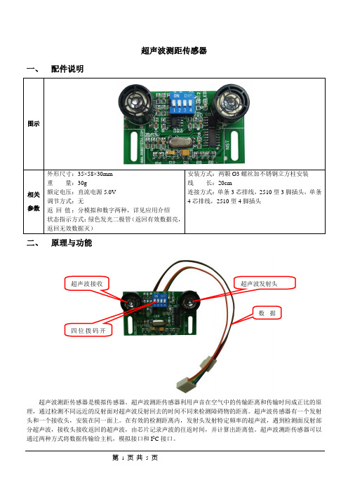
超声波测距传感器一、配件说明二、原理与功能超声波接收超声波发射头数据四位拨码开超声波测距传感器是模拟传感器。
超声波测距传感器利用声音在空气中的传输距离和传输时间成正比的原理,通过检测不同远近的反射面对超声波反射回去的时间不同来检测障碍物的距离。
超声波传感器有一个发射头和一个接收头,安装在同一面上。
在有效的检测距离内,发射头发射特定频率的超声波,遇到检测面反射部分超声波,接收头接收返回的超声波,由芯片记录声波的往返时间,并计算出距离值。
超声波测距传感器可以通过两种方式将数据传输给主机,模拟接口和I2C接口。
三、 应用介绍3.1 使用说明老机器人用户请参阅3.1节模拟接口使用方法部分,新机器人用户请参阅3.1.1节模拟接口使用方法和3.1.2节I 2C 接口使用方法两部分。
3.1.1 模拟接口使用方法使用模拟接口时将三线插头接至主机模拟口。
无需设置I 2C 地址,拨码开关前三位无效;可选择短距离模式和长距离模式,见下图所示:模式选择,使用四位拨码开关的第四位,可选模式为:短距离模式,长距离模式4下:短距离模式,5cm~200cm ;4上:长距离模式,30cm~300cm ;I 2C 接口使用方法当使用I 2C 接口时将四线插头接至I 2C 总线上。
需设置I 2C 地址,见下图所示,模式选择和模拟接口使用方法一致。
地址选择:采用I 2C 接口,使用四位拨码开关的前三位,可选地址为0xB0,0xB2,0xB4,0xB6,0xB8,0xBA ,0xBC ,0xBE ;1下2下3下:地址为0xB0; 1下2下3上:地址为0xB2; 1下2上3下:地址为0xB4;1下2上3上:地址为0xB6; 1上2下3下:地址为0xB8; 1上2下3上:地址为0xBA ;1上2上3下:地址为0xBC;1上2上3上:地址为0xBE;3.2参考数据注:以上数据为短距离模式模拟输出的部分参考数据,主机模拟输入口为8位AD采样。
长距离模式数据类似,只是测距范围不同。
banner超声波传感器说明书
banner超声波传感器说明书1. 产品概述:- 提供Banner超声波传感器的型号、规格和技术参数等基本信息。
- 描述传感器的工作原理和应用场景,以便用户了解其基本原理和适用范围。
2. 安装与连接:- 提供安装传感器的步骤和注意事项,包括传感器位置选择、安装固定方式等。
- 描述传感器的接线方式和连接器类型,确保正确连接和可靠传输信号。
3. 参数设置:- 介绍传感器的可调参数,如灵敏度、探测距离、传感器输出等。
- 提供设置的方法和具体步骤,确保用户能根据实际需要进行参数配置。
4. 工作原理和指示:- 详细阐述超声波传感器的工作原理,包括发射和接收超声波信号的过程。
- 描述指示灯的工作状态和含义,以便用户在使用过程中监测传感器运行情况。
5. 故障排除:- 列出常见问题和故障案例,并提供相应的排除方法和解决方案。
- 完善的故障排除流程图和步骤,方便用户快速解决问题。
6. 安全使用与注意事项:- 提供安全操作指南,包括使用适当的工作电压、避免碰撞或振动等。
- 警示用户避免直接暴露于极端环境下,如强光、高温或潮湿环境。
- 强调合适的维护保养,如定期清理传感器表面灰尘和污渍,确保传感器长期可靠工作。
7. 附件和技术支持:- 列出传感器的附件清单,如安装支架、固定螺丝等。
- 提供联系方式,用户可随时联系我们的技术支持团队,获得更多帮助和解答。
感谢您仔细阅读我们为您编写的Banner超声波传感器说明书。
我们建议您在使用前详细阅读,并按照说明进行正确操作和安装。
如有任何疑问或需要进一步的技术支持,请联系我们的客服中心。
我们期待与您合作并为您提供满意的产品和服务。
超声传感器UC500-L2-E7-V15用户手册说明书

Ultrasonic sensorUC500-L2-E7-V15<Sensor head bidirectional and rotatable<Function indicators visible from all directions<Quick mounting bracket<Selectable sound lobe width<ProgrammableSingle head systemedate:222-1-24Dateofissue:222-1-24Filename:27776_eng.pdfe d a t e : 2022-01-24 D a t e of i s s u e : 2022-01-24 F i l e n a m e : 277760_e ng .p d f13421 BN2 WH3 BU4 BK 5GYWire colors in accordance with EN 60947-5-2(brown)(white)(blue)(black)(gray)Characteristic response curveDistance X [mm]Distance Y [mm]wide sound lobe narrow sound lobee d a t e : 2022-01-24 D a t e of i s s u e : 2022-01-24 F i l e n a m e : 277760_e ng .p d fe d a t e : 2022-01-24 D a t e of i s s u e : 2022-01-24 F i l e n a m e : 277760_e ng .p d fe d a t e : 2022-01-24 D a t e of i s s u e : 2022-01-24 F i l e n a m e : 277760_e ng .p d fProgramming procedureThe sensor features two outputs with two programmable switch points, each (for a total of 4). Programming the switch points and the operating mode can be done in two different ways:•via the sensor’s programming buttons•via the serial interface, which requires an external interface adapterThe procedure for programming via the sensor's programming buttons is described below. For programming using the serial interface, please refer to the software manual. Switch points and operating modes of each output can be programmed independently without influencing each other.Note:•Programming is enabled for 5 minutes after power-on. After 5 minutes without programming activity the programming feature will be locked.•During any programming step it is possible to leave the programming routine without changing the sensor settings by pressing the currently used programming button for 10 s.Programming the Switch PointsNotes:•The description below leads you through programming output 1’s switch points. The procedure for output 2 is exactly the same with the only difference, being to use the Programming Button T2.•If the red LED flashes during the programming procedure, it indicates uncertain target detection. In this case, please correct the target alignment until the yellow LED flashes. The new settings will only be stored in the sensor’s memory if the yellow LED flashes.Programming the Near Switch Point1.Place the target at the desired near switch point position2.Press Programming Button T1 for 2s (corresponding yellow LED flashes)3.Press Programming Button T1 briefly (green LED flashes three times for confirmation). The sensor returns to normal operation.Programming of the Far Switch Point1.Place the target at the desired far switch point position2.Press Programming Button T1 for 2s (corresponding yellow LED flashes)3.Press Programming Button T1 for 2s (green LED flashes three times for confirmation). The sensor returns to normal operation.Programming Modes of OperationNote:The description below leads you through programming of the modes of operation for output 1. The procedure for output 2 is exactly the same with the only difference,being to use Programming Button T2.The sensor provides a three step routine to program the modes of operation. In this routine you can program:1.Output function 2.Output behavior 3.Beam widthProgramming the modes is carried out sequentially. To toggle from one mode to the next, press the Programming button for 2s.Press Programming Button T1 for 5s to enter the operating modes programming routine.Programming the output function1.The green LED flashes. The number of flashes indicates the current output function:single flash: Switch point output function double flash: Window output function triple flash: Hysteresis output function.2.Press Programming Button T1 briefly to toggle sequentially through these output functions and select the desired mode.3.Press Programming Button T1 for 2s to save and enter the programming routine for output behaviorProgramming the output behavior1.The yellow LED flashes. The number of flashes indicates the current output behavior:single flash: Normally Open (NO)double flash: Normally Closed (NC).2.Press Programming Button T1 briefly to toggle sequentially through these output behaviors and select the desired mode.3.Press Programming Button T1 for 2s to save and enter the programming routine for beam width.Programming the beam width1.The red LED flashes. The number of flashes indicates the current beam width setting:single flash: narrow double flash: medium triple flash: wide.2.Press Programming Button T1 briefly to toggle sequentially through these beam shapes.3.Press Programming Button T1 for 2s to save and exit the operating modes programming routine.Note:e d a t e : 2022-01-24 D a t e of i s s u e : 2022-01-24 F i l e n a m e : 277760_e ng .p d fReset Sensor to Factory SettingsThe sensor has a feature to reset to factory settings 1.Disconnect the sensor from power supply2.Press and hold one of the Programming Buttons T1 or T23.Connect Sensor to power supply (red and yellow LED flash simultaneously for 5s then green and yellow LED flash simultaneously)4.Release Programming ButtonThe sensor now operates with default factory settings.Factory settingsSee technical data.The sensor is provided with LEDs to indicate various conditions.*) off if yellow LED out2 is onSynchronizationThis sensor features a synchronization input for suppressing ultrasonic mutual interference ("cross talk"). If this input is not connected, the sensor will operate freewheeling using internally generated clock pulses. It can be synchronized by applying an external square wave or by means of appropriate programming via the serial interface. Each falling edge of the synchronization pulse triggers transmission of a single ultrasonic pulse. If the synchronization signal remains low for ≥ 1 second, the sensor will revert to normal operating mode. Normal operating mode can also be activated by opening the signal connection to the synchronization input.(See note below)If the synchronization input goes to a high level for > 1 second, the sensor will switch to standby mode, indicated by the green LED. In this mode, the output(s) will remain in the last valid output state. When using the external synchronization feature, please refer to the software description.Note:If the option for synchronization is not used, the synchronization input has to be connected to ground (0V) or the sensor has to be operated via a V1 cordset (4-pin).The synchronization function cannot be activated during programming mode and vice versa.The following synchronization modes are possible:1.Several sensors (max. number see technical data) can be synchronized together by interconnecting their respective synchronization inputs. In this case, each sensor alternately transmits ultrasonic pulses in a self multiplexing mode. No two sensors will transmit pulses at the same time. (See note below)2.Several sensors (max. number see technical data) can be synchronized together by interconnecting their respective synchronization inputs. Due to programming via the sensors interface one sensor acts as a master device, all the others as slave devices. (see description of the interface) In this master / slave mode the sensors are triggered in parallel and are synchronized by a common synchronization pulse, provided by the master device.3.Multiple sensors can be controlled by the same external synchronization signal. In this mode the sensors are triggered in parallel and are synchronized by a common external synchronization pulse. All sensors must be parameterized for external synchronization by means of the sensor interface. See software description.4.A separate synchronization pulse can be sent to each individual sensor. In this mode the sensors operate in external multiplex mode. (See note below). All sensors must be parameterized for external synchronization by means of the sensor interface. See software description.5.A high level (+U B ) or a low level (-U B )on the synchronization input switches the sensor to standby mode if it is parameterized for external synchronization.Note:Sensor response times will increase proportionally to the number of sensors that are in the synchronization string. This is a result of the multiplexing of the ultrasonic transmit and receive signal and the resulting increase in the measurement cycle time.Note:The sensors syncronization input delivers an output current in case of low level and burdens with its input impedance in case of high level. Please Green LEDYellow LED out1 / out2Red LED During Normal operation Proper operationInterference (e.g. compressed air)On *)Off Switching state output 1 / output 2remains in previous stateOff On During Switch Point Programming Object detected No object detectedConfirmation after Programming Programming failed warningOff OffTriple flashingOff Flashing Off Off Off Off Flashing OffTriple flashing During Sensor Mode Programming Programming the output function Programming the output behaviour Programming the beam widthFlashing Off OffOff Flashing OffOff Off Flashinge d a t e : 2022-01-24 D a t e of i s s u e : 2022-01-24 F i l e n a m e : 277760_e ng .p d fdriver current against 0V n * output current (n = number of sensors to be synchronized).。
- 1、下载文档前请自行甄别文档内容的完整性,平台不提供额外的编辑、内容补充、找答案等附加服务。
- 2、"仅部分预览"的文档,不可在线预览部分如存在完整性等问题,可反馈申请退款(可完整预览的文档不适用该条件!)。
- 3、如文档侵犯您的权益,请联系客服反馈,我们会尽快为您处理(人工客服工作时间:9:00-18:30)。
超声波测距传感器
[(模拟传感器)主板模拟接口(A2 ~A6)、扩展板模拟接口(A16~A31)、I2C接口(新机器人)] 一、配件说明
二、 原理与功能
超声波测距传感器是模拟传感器。
超声波测距传感器利用声音在空气中的传输距离和传输时间成正比的原
理,通过检测不同远近的反射面对超声波反射回去的时间不同来检测障碍物的距离。
超声波传感器有一个发射头和一个接收头,安装在同一面上。
在有效的检测距离内,发射头发射特定频率的超声波,遇到检测面反射部分超声波,接收头接收返回的超声波,由芯片记录声波的往返时间,并计算出距离值。
超声波测距传感器可以通过两种方式将数据传输给主机,模拟接口和I 2C 接口。
三、 应用介绍
3.1 使用说明
老机器人用户请参阅3.1节模拟接口使用方法部分,新机器人用户请参阅3.1.1节模拟接口使用方法和3.1.2节I 2C 接口使用方法两部分。
3.1.1 模拟接口使用方法
使用模拟接口时将三线插头接至主机模拟口。
无需设置I 2C 地址,拨码开关前三位无效;可选择短距离模式和长距离模式,见下图所示:
模式选择,使用四位拨码开关的第四位,可选模式为:短距离模式,长距离模式
4下:短距离模式,5cm~200cm ;
4上:长距离模式,30cm~300cm ;
超声波接收头 超声波发射头
四位拨码开关
数据线
I2C接口使用方法
当使用I2C接口时将四线插头接至I2C总线上。
需设置I2C地址,见下图所示,模式选择和模拟接口使用方法一致。
地址选择:采用I2C接口,使用四位拨码开关的前三位,可选地址为0xB0,0xB2,0xB4,0xB6,0xB8,0xBA,0xBC,0xBE;
1下2下3下:地址为0xB0;
1下2下3上:地址为0xB2;
1下2上3下:地址为0xB4;
1下2上3上:地址为0xB6;
1上2下3下:地址为0xB8;
1上2下3上:地址为0xBA;
1上2上3下:地址为0xBC;
1上2上3上:地址为0xBE;
3.2
参考数据
注:以上数据为短距离模式模拟输出的部分参考数据,主机模拟输入口为8位AD 采样。
长距离模式数据类似,只是测距范围不同。
数字输出(I 2C 接口)的值和实际距离值一致(超出测距范围输出888)。
由于声在空气中传播的速度和温度有关,数据在不同的季节有所不同,请用户在使用中根据实际的测量结果重新确定实际距离和返回数据的对应关系。
四、 安装方法
将传感器的左右孔用螺钉固定在立方柱上,将立方柱固定在机器人上。
在安装过程中,确保超声波垂直发射到被测物体表面,这样会令测量结果更加精确。
(在具体项目中请用户根据实际情况安装)
五、示例程序
假设在模拟3口(A3)接上一个超声波传感器来说明它的使用。
本例功能:检测木质挡板。
到达白线一定距离的时候停止(通过超声波测距传感器的参数决定),否则一直前进。
程序及流程图如下所示:
运行程序,观察机器人行走可知:无挡板时,一直前进;有挡板时,即停止前进。
六、常见故障
超声波测距传感器由于没有外壳保护,在使用过程中切勿碰撞,以防损坏器件。
七、注意事项
由于超声波的发射和接收不是一条直线,有一定的角度,所以超声波测距传感器会受环境中其他障碍物的影响,和其他超声波测距传感器的干扰。
当出现这些情况时,请尽可能改善环境的质量,重新安装超声波测距传感器的位置。