EELS mapping step-by-step
制作日式烤鳗鱼饭英语作文

制作日式烤鳗鱼饭英语作文Title: Writing a Document on Making Japanese Grilled Eel Rice Japanese Grilled Eel Rice, also known as Unagi Don, is a popular and delicious dish in Japanese cuisine. The combination of juicy and flavorful grilled eel over a bed of steamed rice creates a harmonious blend of textures and tastes. In this document, we will explore the process of preparing this traditional Japanese delicacy step by step.Firstly, the key ingredient required for making Japanese Grilled Eel Rice is, of course, the eel itself. Eels aretypically sold skinned and precooked in Japanese markets, making the preparation process much simpler. However, if you prefer to use fresh eel, you will need to skin and debone it before grilling.To begin, prepare the eel by slicing it into thick pieces. Next, the eel pieces are typically marinated in a sauce made from a blend of soy sauce, mirin, sake, and sugar. This marinade imparts a sweet and savory flavor to the eel, enhancing itstaste during grilling.Once the eel has marinated for an adequate amount of time, it is time to grill it. The eel is placed on a grill and cooked until the surface becomes slightly charred and crispy, while the inside remains tender and succulent. The grilling process helpsto caramelize the marinade, creating a rich and umamipacked flavor.While the eel is grilling, the rice should be prepared. Japanese shortgrain rice is the preferred choice for making Unagi Don, as its sticky texture complements the eel perfectly. Cook the rice according to the package instructions and keep it warm until ready to assemble the dish.To assemble the Japanese Grilled Eel Rice bowl, start by placing a generous portion of steamed rice in a bowl. Arrange the grilled eel pieces on top of the rice, drizzling any remaining marinade over the dish. Garnish with thinly sliced green onions and toasted sesame seeds for added flavor andvisual appeal.In Japan, Japanese Grilled Eel Rice is often served with a side of pickles or miso soup to balance out the richness of the eel. The dish is enjoyed yearround but is especially popular during the summer months when eel is believed to provide stamina and energy to combat the heat.In conclusion, making Japanese Grilled Eel Rice is a rewarding culinary experience that allows you to savor the flavors of traditional Japanese cuisine. With the right ingredients and techniques, you can recreate this beloved dishin your own kitchen and enjoy a taste of Japan's rich culinary heritage.。
尚学堂SSH-188P

版权所有:尚学堂科技
尚学堂
手把手教程
Struts+Hibernate+Spring
我们将需要创建如下文件
一个ActionForm – LoginActionForm.java 一个Action – LoginAction.java struts-config.xml文件 三个页面 登录页面 – login.jsp 登录成功提示页面 – login_success.jsp 登录失败提示页面 – login_error.jsp 就这些!没别的了!!
版权所有:尚学堂科技
尚学堂
手把手教程
Struts+Hibernate+Spring
创建LoginActionForm.java
ActionForm是一个JavaBean,需继承 org.apache.struts.action.ActionForm类, 它捕获通过HTTP请求传送的参数 ActionForm针对每个HTML表单中的字段 具有一个对应的属性 ActionServlet匹配请求中的参数和 ActionForm中的属性,并调用ActionForm 中的setter方法,将参数传入ActionForm 我们的login.jsp有username和password 两个表单字段(下面将会看到),所以, 我们需要定义ActionForm中相应的setter 方法:setUsername和setPassword方法 ActionForm中的getter/setter方法,可以 通过Eclipse集成环境,自动生成 ActionForm中的内部属性全部定义为私有 的(private),并通过公共(public)的 getter/setter方法来访问
版权所有:尚学堂科技
Open Cascade手册(6)

Data ExchangeSTEP Import/ExportUser’s GuideVersion 6.3 / September 20082 Overview Copyright © 2008, by Open CASCADE S.A.S.PROPRIETARY RIGHTS NOTICE: All rights reserved. No part of this material may be reproduced ortransmitted in any form or by any means, electronic, mechanical, or otherwise, including photocopyingand recording or in connection with any information storage or retrieval system, without the permissionin writing from Open CASCADE S.A.S.The information in this document is subject to change without notice and should not be construed as acommitment by Open CASCADE S.A.S. Open CASCADE S.A.S. assures no responsibility for anyerrors that may appear in this document.The software described in this document is furnished under a license and may be used or copied onlyin accordance with the terms of such a license.CAS.CADE and Open CASCADE are registered trademarks of Open CASCADE S.A.S. Other brandor product names are trademarks or registered trademarks of their respective holders.NOTICE FOR USERS:This User Guide is a general instruction for Open CASCADE study. It may be incomplete and evencontain occasional mistakes, particularly in examples, samples, etc. Open CASCADE S.A.S. bears noresponsibility for such mistakes. If you find any mistakes or imperfections in this document, or if youhave suggestions for improving this document, please, contact us and contribute your share to thedevelopment of Open CASCADE Technology: bugmaster@Tour Opus 1277, Esplanade du Général de Gaulle92914 PARIS LA DEFENSEFRANCEContents1. OVERVIEW (5)2. READING STEP (6)2.1.P ROCEDURE (6)2.2.D OMAIN COVERED (6)2.2.1. Assemblies (6)2.2.2. Shape representations (6)2.2.3. Topological entities (7)2.2.4. Geometrical entities (7)2.3.D ESCRIPTION OF THE PROCESS (7)2.3.1. Loading the STEP file (7)2.3.2. Checking the STEP file (7)2.3.3. Setting the translation parameters (8)2.3.4. Performing the STEP file translation (14)2.3.5. Getting the translation results (14)2.3.6. Selecting STEP entities for translation (15)2.4.M APPING STEP ENTITIES TO O PEN CASCADE SHAPES (17)2.4.1. Assembly structure representation entities (17)2.4.2. Models (19)2.4.3. Topological entities (19)2.4.4. Geometrical entities (20)2.5.T OLERANCE MANAGEMENT (23)2.5.1. Values used for tolerances during reading STEP (23)2.5.2. Initial setting of tolerances in translating objects (23)2.5.3. Transfer process (24)2.6.C ODE ARCHITECTURE (27)2.6.1. List of the classes (27)2.6.2. API classes (27)2.6.3. Graph of calls (27)2.7.E XAMPLE (28)3. WRITING STEP (30)3.1.P ROCEDURE (30)3.2.D OMAIN COVERED (30)3.2.1. Writing geometry and topology (30)3.2.2. Writing assembly structures (30)3.3.D ESCRIPTION OF THE PROCESS (31)3.3.1. Initializing the process (31)3.3.2. Setting the translation parameters (31)3.3.3. Performing the Open CASCADE shape translation (34)3.3.4. Writing the STEP file (35)3.4.M APPING O PEN CASCADE SHAPES TO STEP ENTITIES (35)3.4.1. Assembly structures and product information (35)3.4.2. Topological shapes (36)3.4.3. Geometrical objects (37)3.5.T OLERANCE MANAGEMENT (39)3.6.C ODE ARCHITECTURE (40)3.6.1. List of the classes (40)3.6.2. API classes (40)3.6.3. Graph of calls (41)3.7.E XAMPLE (42)4. API FOR READING/WRITING STEP (43)4.1.O VERVIEW (43)44.2.P ACKAGE STEPC ONTROL (43)4.2.1. General description (43)4.2.2. Enumeration STEPControl_StepModelType (43)4.2.3. Class STEPControl_Controller (44)4.2.4. Class STEPControl_Reader (45)4.2.5. Class STEPControl_Writer (46)4.2.6. Class STEPControl_ActorRead (48)4.2.7. Class STEPControl_ActorWrite (49)4.3.P ACKAGE STEPC ONSTRUCT (51)4.3.1. General description (51)4.3.2. Class STEPConstruct_Styles (51)4.3.3. Class STEPConstruct_Part (54)5. PHYSICAL STEP FILE READING AND WRITING (59)5.1.A RCHITECTURE OF STEP R EAD AND W RITE CLASSES (59)5.1.1. General principles (59)5.1.2. Complex entities (59)5.2.P HYSICAL FILE READING (59)5.2.1. Loading a STEP file and syntactic analysis of its contents (60)5.2.2. Mapping STEP entities to arrays of strings (60)5.2.3. Creating empty Open CASCADE objects that represent STEP entities (60)5.2.4. Initializing Open CASCADE objects (60)5.2.5. Building a graph (60)5.3.H OW TO ADD A NEW ENTITY IN SCOPE OF THE STEP PROCESSOR (60)5.4.P HYSICAL FILE WRITING (61)5.4.1. Building a references graph (62)5.4.2. Transferring data from the model to a sequence of strings (62)5.4.3. Writing the sequence of strings into the file (62)5.5.H OW TO ADD A NEW ENTITY TO WRITE IN THE STEP FILE (62)6. USING DRAW (63)6.1.DRAW STEP C OMMANDS O VERVIEW (63)6.2.S ETTING THE INTERFACE PARAMETERS (63)6.3.R EADING A STEP FILE (63)6.4.A NALYZING THE DATA TRANSFERRED (65)6.4.1. Checking file contents (65)6.4.2. Estimating the results of reading STEP (67)6.5.W RITING A STEP FILE (68)6.6.I NDEX OF USEFUL XSDRAW COMMANDS (69)7. READING FROM AND WRITING TO XDE (70)7.1.D ESCRIPTION OF THE PROCESS (70)7.1.1. Loading a STEP file (70)7.1.2. Checking the loaded STEP file (70)7.1.3. Setting the parameters for translation to XDE (70)7.1.4. Performing the translation of a STEP file to XDE (70)7.1.5. Initializing the process of translation from XDE to STEP (71)7.1.6. Setting the parameters for translation from XDE to STEP (71)7.1.7. Performing the translation of an XDE document to STEP (71)7.1.8. Writing a STEP file (71)Overview51. Overview This manual is intended to provide technical documentation on the Open CASCADE STEP processor and to help Open CASCADE users with the use of the STEP processor (to read and write STEP files). STEP files conforming to AP 214, AP 203 and partially AP 209 can be read. STEP files that are produced by this interface conform to STEP AP 214 or AP 203, according to the user option.Only geometrical, topological STEP entities (shapes) and assembly structures are translated by the basic translator described in sections 2 to 6. Data that cannot be translated on this level are also loaded from a STEP file and can be translated later. XDE STEP translator (see section 7 “Reading from and writing to XDE”) translates names, colors, layers, validation properties and other data associated with shapes and assemblies into XDE document.File translation is performed in the programming mode, via C++ calls.For testing the STEP component in DRAW Test Harness, a set of commands for reading and writing STEP files and analysis of relevant data are provided by the TKXSDRAW plugin.6 Reading STEP2. Reading STEP2.1. ProcedureYou can translate a STEP file into an Open CASCADE shape in the following steps:1. load the file,2. check file consistency,3. set the translation parameters,4. perform the translation,5. fetch the results.2.2. Domain covered2.2.1. AssembliesThe "ProSTEP Round Table Agreement Log" (version July 1998), item 21, defines two alternatives for the implementation of assembly structure representations: using mapped_item entities and using representation_relationship_with_transformation entities. Both these alternative representations are recognized and processed at reading. On writing, the second alternative is always employed.Handling of assemblies is implemented in two separate levels: firstly STEP assembly structures are translated into Open CASCADE shapes, and secondly the Open CASCADE shape representing the assembly is converted into any data structure intended for representing assemblies (for example, OCAF).The first part of this document describes the basic STEP translator implementing translation of the first level, i.e. translation to Open CASCADE Shapes. On this level, the acyclic graph representing the assembly structure in a STEP file is mapped into the structure of nested TopoDS_Compounds in Open CASCADE. The (sub)assemblies become (sub)compounds containing shapes which are the results of translating components of that (sub)assembly. The sharing of components of assemblies is preserved as Open CASCADE sharing of subshapes in compounds.The attributive information attached to assembly components in a STEP file (such as names and descriptions of products, colors, layers etc.) can be translatd after the translation of the shape itself by parsing the STEP model (loaded in memory). Several tools from the package STEPConstruct provide functionalities to read styles (colors), validation properties, product information etc.Implementation of the second level of translation (conversion to XDE data structure) is provided by XDE STEP translator and is described in section 7.2.2.2. Shape representationsLength units, plane angle units and the uncertainty value are taken from shape_representation entities. This data is used in the translation process.The types of STEP representation entities that are recognized are:• advanced_brep_shape_representation• faceted_brep_shape_representation• manifold_surface_shape_representationReading STEP7• geometrically_bounded_wireframe_shape_representation• geometrically_bounded_surface_shape_representation•hybrid representations (shape_representation containing models of different type)2.2.3. Topological entitiesThe types of STEP topological entities that can be translated are:• vertices• edges• loops• faces• shells• solidsFor further information see 2.4Mapping STEP entities to Open CASCADE shapes.2.2.4. Geometrical entitiesThe types of STEP geometrical entities that can be translated are:• points• vectors• directions• curves• surfacesFor further information see 2.4 Mapping STEP entities to Open CASCADE shapes.2.3. Description of the process2.3.1. Loading the STEP fileBefore performing any other operation you have to load the file with:STEPControl_Reader reader;IFSelect_ReturnStatus stat = reader.ReadFile("filename.stp");Loading the file only memorizes the data, it does not translate it.2.3.2. Checking the STEP fileThis step is not obligatory. Check the loaded file with:reader.PrintCheckLoad(failsonly,mode);Error messages are displayed if there are invalid or incomplete STEP entities, giving you the information on the cause of error.8 Reading STEPOnly fail messages are displayed if failsonly is true. All messages are displayed if failsonly is false. Your analysis of the file can be either message-oriented or entity-oriented. Choose your preference with:IFSelect_PrintCount mode = IFSelect_xxxWhere xxx can be one of the following:ItemsByEntity - gives a sequential list of all messages per STEP entity,CountByItem - gives the number of STEP entities with their types per messageListByItem- gives the number of STEP entities with their types and rank numbers per message2.3.3. Setting the translation parametersThe following parameters can be used to translate a STEP file into an Open CASCADE shape.If you give a value that is not within the range of possible values it will simply be ignored.read.precision.modeDefines which precision value will be used during translation (see section 2.5 below for details on precision and tolerances)."File" (0): the precision value is set to length_measure in uncertainty_measure_with_unit from STEP file."User" (1): the precision value is that of the read.precision.val parameter.Read this parameter with:Standard_Integer ic = Interface_Static::IVal("read.precision.mode"); Modify this parameter with:if(!Interface_Static::SetIVal("read.precision.mode",1)).. error ..Default value is "File" (0).read.precision.val:User defined precision value. This parameter gives the precision for shape construction when the read.precision.mode parameter value is 1.0.0001: defaultany real positive (non null) value.This value is a basic value of tolerance in the processor. The value is in millimeters, independently of the length unit defined in the STEP file.Read this parameter with:Standard_Real rp = Interface_Static::RVal("read.precision.val");Modify this parameter with:if(!Interface_Static::SetRVal("read.precision.val",0.01)).. error ..Default value is 0.0001.Reading STEP9NOTEThe value given to this parameter is a basic value for ShapeHealing algorithms and the processor. It does its best to reach it. Under certain circumstances, the value you give may not be attached to all of the entities concerned at the end of processing. STEP-to-OpenCASCADE translation does not improve the quality of the geometry in the original STEP file. This means that the value you enter may be impossible to attach to all shapes with the given quality of the geometry in the STEP file.read.maxprecision.valDefines the maximum allowed tolerance (in mm) of the shape. It should be not less than the basic value of tolerance set in the processor (either the uncertainty from the file or read.precision.val). Actually, the maximum between read.maxprecision.val and the basis tolerance is used to define the maximum allowed tolerance.Read this parameter with:Standard_Real rp = Interface_Static::RVal("read.maxprecision.val"); Modify this parameter with:if(!Interface_Static::SetRVal("read.maxprecision.val",0.1)).. error ..Default value is 1.Note that maximum tolerance even explicitly defined by the user may be insufficient to ensure the validity of the shape (if real geometry is of bad quality). Therefore the user is provided with an additional parameter, which allows him to choose: either he prefers to ensure the shape validity or he rigidly sets the value of maximum tolerance. In the first case there is a possibility that the tolerance will not have any upper limit, in the second case the shape may be invalid.read.maxprecision.mode:Defines the mode of applying the maximum allowed tolerance. Its possible values are:0 ("Preferred") - maximum tolerance is used as a limit but sometimes it can be exceeded (currently,only for deviation of a 3D curve and pcurves of an edge, and vertices of such edge) toensure the shape validity,1 ("Forced") - maximum tolerance is used as a rigid limit, i.e. no tolerance can exceed it and if it isthe case, the tolerance is trimmed by the maximum tolerance.Read this parameter with:Standard_Integer ic = Interface_Static::IVal("read.maxprecision.mode"); Modify this parameter with:if(!Interface_Static::SetIVal("read.maxprecision.mode",1)).. error ..Default value is 0 ("Preferred").read.stdsameparameter.modedefines the use of BRepLib::SameParameter. Its possible values are:0 ("Off") - BRepLib::SameParameter is not called,1 ("On") - BRepLib::SameParameter is called.The functionality of BRepLib::SameParameter is used through ShapeFix_Edge::SameParameter. It ensures that the resulting edge will have the lowest tolerance taking pcurves either unmodified from the STEP file or modified by BRepLib::SameParameter.Read this parameter with:10 Reading STEPStandard_Integer mv =Interface_Static::IVal("read.stdsameparameter.mode");Modify this parameter with:if (!Interface_Static::SetIVal ("read.stdsameparameter.mode",1)).. error ..;Deafault value is 0 ("Off").read.surfacecurve.mode:a preference for the computation of curves in an entity which has both 2D and 3D representation.Each TopoDS_Edge in TopoDS_Face must have a 3D and 2D curve that references the surface.If both 2D and 3D representation of the entity are present, the computation of these curves depends on the following values of parameter:"Default" (0): no preference, both curves are taken (default value),"3DUse_Preferred" (3): 3D curves are used to rebuild 2D ones.Read this parameter with:Standard_Integer rp = Interface_Static::IVal("read.surfacecurve.mode"); Modify this parameter with:if(!Interface_Static::SetIVal("read.surfacecurve.mode",3)).. error ..Default value is (0).read.encoderegularity.angleThis parameter is used for call to BRepLib::EncodeRegularity() function which is called for the shape read from an IGES or a STEP file at the end of translation process. This function sets the regularity flag of the edge in the shell when this edge is shared by two faces. This flag shows the continuity these two faces are connected with at that edge.Read this parameter with:Standard_Real era =Interface_Static::RVal("read.encoderegularity.angle");Modify this parameter with:if (!Interface_Static::SetRVal ("read.encoderegularity.angle",0.1)).. error ..;Default value is 0.01.step.angleunit.modeThis parameter is obsolete (it was required in the past for STEP files with a badly encoded angle unit). It indicates what angle units should be used when a STEP file is read: the units from file (default), or forced RADIANS or DEGREES.Default value is Fileread.step.sequenceThese two parameters define the name of the resource file and the name of the sequence of operators (defined in that file) for Shape Processing, which is automatically performed by the STEP translator. Shape Processing is a user-configurable step, which is performed after translation and consists inapplying a set of operators to a resulting shape. This is a very powerful tool allowing customizing the shape and adapting it to the needs of a receiving application. By default the sequence consists of a single operator ShapeFix - that is how Shape Healing is called from the STEP translator.Please find an example of the resource file for STEP (which defines parameters corresponding to the sequence applied by default, i.e. if the resource file is not found) in the Open CASCADE installation, by the path %CASROOT%/src/XSTEPResource/STEP ($CASROOT/src/XSTEPResource/STEP).In order for the STEP translator to use that file, you have to define the CSF_STEPDefaults environment variable, which should point to the directory where the resource file resides. Note that if you change parameter , you will change the name of the resource file and the environment variable correspondingly.Default values: - STEP, read.step.sequence - FromSTEP.read.scale.unitThis parameter is obsolete (the parameter xstep.cascade.unit should be used instead when necessary). If it is set to 'M', the shape is scaled 0.001 times (as if it were in meters) after translation from IGES or STEP.Default value is MM.xstep.cascade.unitThis parameter defines units to which a shape should be converted when translated from IGES or STEP to CASCADE. Normally it is MM; only those applications that work internally in units other than MM should use this parameter.Default value is MM.read.step.product.mode:Defines the approach used for selection of top-level STEP entities for translation, and for recognition of assembly structures1 ("ON") - PRODUCT_DEFINITION entities are taken as top-level ones; assembly structure isrecognized by NEXT_ASSEMBLY_USAGE_OCCURRENCE entities. This is regularmode for reading valid STEP files conforming to AP 214, AP203 or AP 209.0 ("OFF") - SHAPE_DEFINITION_REPRESENTATION entities are taken as top-level ones;assembly is recognized by CONTEXT_DEPENDENT_SHAPE_REPRESENTATIONentities. This is compatibility mode, which can be used for reading legacy STEP filesproduced by older versions of STEP translators and having incorrect or incompleteproduct information.Read this parameter with:Standard_Integer ic = Interface_Static::IVal("read.step.product.mode"); Modify this parameter with:if(!Interface_Static::SetIVal("read.step.product.mode",1)).. error ..Default value is 1 ("ON").Note that the following parameters have effect only if read.step.product.mode is ON.read.step.product.context:When reading AP 209 STEP files, allows selecting either only ‘design’ or ‘analysis’, or both types of products for translation1 ("all") - translate all products2 ("design") - translate only products that have PRODUCT_DEFINITION_CONTEXT with fieldlife_cycle_stage set to ‘design’3 (“analysis”) - translate only products associated with PRODUCT_DEFINITION_CONTEXT entitywhose field life_cycle_stage set to ‘analysis’Note that in AP 203 and AP214 files all products should be marked as ‘design’, so if this mode is set to ‘analysis’, nothing will be read.Read this parameter with:Standard_Integer ic =Interface_Static::IVal("read.step.product.context"); Modify this parameter with:if(!Interface_Static::SetIVal("read.step.product.context",1)).. error ..Default value is 1 ("all").read.step.shape.repr:Specifies preferred type of representation of the shape of the product, in case if a STEP file contains more than one representation (i.e. multiple PRODUCT_DEFINITION_SHAPE entities) for a single product1 ("All") - Translate all representations (if more than one, put in compound).2 ("ABSR") - Prefer ADVANCED_BREP_SHAPE_REPRESENTATION3 ("MSSR") - Prefer MANIFOLD_SURFACE_SHAPE_REPRESENTATION4 ("GBSSR") - Prefer GEOMETRICALLY_BOUNDED_SURFACE_SHAPE_REPRESENTATION5 ("FBSR") - Prefer FACETTED_BREP_SHAPE_REPRESENTATION6 ("EBWSR") - Prefer EDGE_BASED_WIREFRAME_SHAPE_REPRESENTATION7 ("GBWSR") - Prefer GEOMETRICALLY_BOUNDED_WIREFRAME _SHAPE_REPRESENTATION When this option is not equal to 1, for products with multiple representations the representation having a type closest to the selected one in this list will be translated.Read this parameter with:Standard_Integer ic = Interface_Static::IVal("read.step.shape.repr"); Modify this parameter with:if(!Interface_Static::SetIVal("read.step.shape.repr",1)).. error ..Default value is 1 ("All").read.step.assembly.level:Specifies which data should be read for the products found in the STEP file:1 ("All") - Translate both the assembly structure and all associated shapes. If both shape andsub-assemblies are associated with the same product, all of them are read and put ina single compound.Note that this situation is confusing, as semantics of such configuration is not definedclearly by the STEP standard (whether this shape is an alternative representation ofthe assembly or is an addition to it), therefore warning will be issued in such case.2 ("assembly") - Translate the assembly structure and shapes associated with parts only (not with sub-assemblies).3 ("structure") - Translate only the assembly structure without shapes (a structure of emptycompounds). This mode can be useful as an intermediate step in applicationsrequiring specialized processing of assembly parts.4 ("shape") - Translate only shapes associated with the product, ignoring the assembly structure (ifany). This can be useful to translate only a shape associated with specific product, asa complement to “assembly” mode.Read this parameter with:Standard_Integer ic =Interface_Static::IVal("read.step.assembly.level"); Modify this parameter with:if(!Interface_Static::SetIVal("read.step.assembly.level ",1)).. error ..Default value is 1 ("All").read.step.shape.relationship:Defines whether shapes associated with the main SHAPE_DEFINITION_REPRESENTATION entity of the product via SHAPE_REPRESENTATIONSHIP_RELATION should be translated. This kind of association is used for the representation of hybrid models (i.e. models whose shape is composed of different types of representations) in AP 203 files since 1998, but it can be also used to associate auxiliary data with the product. This parameter allows to avoid translation of such auxiliary data.1 ("ON") - translate0 ("OFF") - do not translateRead this parameter with:Standard_Integer ic =Interface_Static::IVal("read.step.shape.relationship");Modify this parameter with:if(!Interface_Static::SetIVal("read.step.shape.relationship",1)).. error ..Default value is 1 ("ON").read.step.shape.aspect:Defines whether shapes associated with the PRODUCT_DEFINITION_SHAPE entity of the product via SHAPE_ASPECT should be translated. This kind of association was used for the representation of hybrid models (i.e. models whose shape is composed of different types of representations) in AP 203 files before 1998, but it is also used to associate auxiliary information with the sub-shapes of the part. Though STEP translator tries to recognize such cases correctly, this parameter may be useful to avoid unconditionally translation of shapes associated via SHAPE_ASPECT entities.1 ("ON") - translate0 ("OFF") - do not translateRead this parameter with:Standard_Integer ic =Interface_Static::IVal("read.step.shape.aspect"); Modify this parameter with:if(!Interface_Static::SetIVal("read.step.shape.aspect",1)).. error ..Default value is 1 ("ON").2.3.4. Performing the STEP file translationPerform the translation according to what you want to translate. You can choose either root entities (all or selected by the number of root), or select any entity by its number in the STEP file. There is a limited set of types of entities that can be used as starting entities for translation. Only the following entities are recognized as transferable:• product_definition• next_assembly_usage_occurrence• shape_definition_representation•subtypes of shape_representation (only if referred representation is transferable)• manifold_solid_brep• brep_with_voids• faceted_brep• faceted_brep_and_brep_with_voids• shell_based_surface_model•geometric_set and geometric_curve_set• mapped_item•subtypes of face_surface (including advanced_face)•subtypes of shape_representation_relationship• context_dependent_shape_representationThe following methods are used for translation:•Translate a root entity identified by its rank with:Standard_Boolean ok = reader.TransferRoot(rank);•Translate an entity identified by its rank with:Standard_Boolean ok = reader.TransferOne(rank);•Translate a list of entities in one operation with (this method returns the number of successful translations):Standard_Integer num = reader.TransferList(list);•Translate all transferable roots with:Standard_Integer NbRoots = reader.NbRootsForTransfer();Standard_Integer num = reader.TransferRoots();2.3.5. Getting the translation resultsEach successful translation operation outputs one shape. A series of translations gives a set of shapes.Each time you invoke TransferOne(), TransferRoot() or TransferList(), their results are accumulated and the counter of results increases. You can clear the results with:reader.ClearShapes();between two translation operations, if you do not, the results from the next translation will be added to the accumulation.TransferRoots() operations automatically clear all existing results before they start.•Get the number of shapes recorded in the result with:Standard_Integer num = reader.NbShapes();•Get the result identified by its rank, where rank is an integer between 1 and NbShapes, with:TopoDS_Shape shape = reader.Shape(rank);•Get the first result of translation with:TopoDS_Shape shape = reader.Shape();•Get all of results in a single shape which is:a null shape if there are no results,in case of a single result, a shape that is specific to that result,a compound that lists the results if there are several results.TopoDS_Shape shape = reader.OneShape();Clearing the accumulation of resultsIf several individual translations follow each other, the results give a list that can be purged with: reader.ClearShapes();which erases the existing results.Checking that translation was correctly performedEach time you invoke Transfer… or TransferRoots(), you can display the related messages with the help of:reader.PrintCheckTransfer(failsonly,mode);This check concerns the last invocation of Transfer… or TransferRoots() only.2.3.6. Selecting STEP entities for translationSelection possibilitiesThere are three selection possibilities. You can select:•the whole file,• a list of entities,• one entity.Whole fileTransferring the whole file means transferring all root entities. The number of roots can be evaluated when the file is loaded:Standard_Integer NbRoots = reader.NbRootsForTransfer();Standard_Integer num = reader.TransferRoots();。
hspice一些注解(进阶)

runlvl 用来设置仿真速度与精度最高精度级别runlvl=6 ,1=fast(事实上设为零,将回到早先的未加入些功能的版本) 6=most accurate 。
默认的值是runlvl=3。
较低数值适合于纯数字电路或大部分数字电路。
Hspice使用的是最好保存的runlvl设置。
通常是结合.option runlvl=5If you set .option ACCURATE then HSPICE limits the RUNLVL value to 5 or 6.p1 input1 0 z0=50 port=1 pulse(0 1.5 100p 40p 40p)Psource dut_in 0 z0=zref port=1 pulse(vlo vhi td tr tf) p 代表port 元件Psource dut_inp dut_inn 0 z0=zref port=1 pulse(vlo vhi td tr tf) 这里定义的是差分的port元件对输出部分,没有源,所以无须加source部分。
Pterm dut_out 0 z0=50 port=2这里要区别在.meas p(m1) ,p()组合是表现功率。
t 无损传输线,结点,阻抗,延迟T1 dut_in 0 node1 0 Z0=50 td=1npar 可复用par(..)输出作为其他端口的输入电压Reusing the PAR(...) Output as Input to Other Elements可使用于.print .probe 的输出.print tran v(5) par('5*cos(6.28*v(10)*v(5)*k/360)') 式子要加单引号括起来IBIS模型使用Input buffer:B_INPUT nd_pc nd_gc nd_in nd_out_of_inOutput buffer:B_OUTPUT nd_pu nd_pd nd_out nd_in [nd_pc nd_gc]Input ECL Buffer:B_INPUT_ECL nd_pc nd_gc nd_in nd_out_of_inOutput ECL Buffer:B_OUTPUT_ECL nd_pu nd_ou t nd_in [nd_pc nd_gc]Tri-state buffer:B_3STATE nd_pu nd_pd nd_out nd_in nd_en [nd_pc nd_gc]Input/Output buffer:B_IO nd_pu nd_pd nd_out nd_in nd_en nd_out_of_in [nd_pc nd_gc](pu and pd are pull-up and pull-down; pc and gc are power clamp and ground clamp; nd simply stands for node.)例子如下:b_out1 nd_pu nd_pd out1 in1+ file = 'at16245.ibs'+ model = 'AT16245_OUT'Search 组合使用.option search (自动寻找库以及包含文件所在的路径)hspice.ini file sets th e default search paths. (sa_146)例子:.OPTION SEARCH='$installdir/parts/signet' 定位到安装路径下去扫描寻找S参数与外部电路连接(si_69)Sxxx nd1 nd2 ... ndN ndRef 所有的节点,其中最后一个点为地参考节点,除地结点共n,共有n个结点。
APEX_主从表单_类似一个简单的form_step_by_step
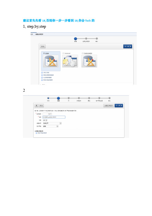
建议首先先看18,否则你一步一步看到18,你会fuck的1, step,by,step234一直下一步5创建成功后,打开sql工作室,创建试图或者表此处用了表:CUX_SLM_QUALIFICATIONSCUX_SLM_ASL_QUALIFICATION下面都是oracle标准表不再附件中MTL_MANUFACTURERShr_all_organization_units视图: CUX_SLM_QUALIFICATIONS_v详细脚本见附件6,创建完成后,点击创建页,7此处选择主从表单8选择你要显示的主表或者视图的字段.9选择从表10,选择主键11,找到2个表之间的关联12选择主表主键序列13,选择从表主键序列14,一路下一步一直到页属性设置标题名:15,设置页签16创建完成,我们来运行下,感觉体验还不够好若点击编辑对应的小图片若点击创建17,接下来在做一些人性化的设置比如form的值列表神马的.找到页3的p_org_id把他做成一个lov,或者列表18,错误,因为之前做的时候都是用的表,没有用view来进行,点击创建后点击保存出现如下错误.这个是因为在做插入的时候是不能直接退视图进行的.但是这个又不像是form.可以写包最终解决办法: 显示的地方sql改为视图的,插入的用基表的,不过不影响前面的文档过程,具体不再贴图,到了个性化在继续贴.只是想体验过程的可以直接用表按上面的过程基本是没有问题的.即选择基表.19,接下来优化20接下来详细报表列:设置asl_id为隐藏,因为此处这个id没有被其他表用到,并赋值为头的QUALIFICATION_ID的值21 生产商low22.设置qulification_type设置flag,没有找到类似checkbox的东西23,此时整体页面呈现效果如下:我们在修改一下标签就更好了点击全部编辑CREATED_BY NUMBER default -1not null,LAST_UPDATED_BY NUMBER default -1not null,LAST_UPDATE_DATE DATE default sysdate not null,LAST_UPDATE_LOGIN NUMBER,ATTRIBUTE_CATEGORY VARCHAR2(30),ATTRIBUTE1 VARCHAR2(240),ATTRIBUTE2 VARCHAR2(240),ATTRIBUTE3 VARCHAR2(240),ATTRIBUTE4 VARCHAR2(240),ATTRIBUTE5 VARCHAR2(240),ATTRIBUTE6 VARCHAR2(240),ATTRIBUTE7 VARCHAR2(240),ATTRIBUTE8 VARCHAR2(240),ATTRIBUTE9 VARCHAR2(240),ATTRIBUTE10 VARCHAR2(240),ATTRIBUTE11 VARCHAR2(240),ATTRIBUTE12 VARCHAR2(240),ATTRIBUTE13 VARCHAR2(240),ATTRIBUTE14 VARCHAR2(240),ATTRIBUTE15 VARCHAR2(240));alter table CUX_SLM_QUALIFICATIONS add constraintCUX_SLM_QUALIFICATIONS_PK primary key (QUALIFICATION_ID);Create Sequence CUX.CUX_SLM_QUALIFICATIONS_S Start With10001;Create Table CUX_SLM_ASL_QUALIFICATION(ASL_QUALIFICATION_ID Number Not Null,ASL_ID Number Not Null,QUALIFICATION_TYPE Varchar2(10) Not Null,MANUFACTURER_ID Number,QUALIFICATION_ID Number,CERTIFICATE_NUMBER Varchar2(100),EXPIRATION_DATE Date,ALERT_LEADTIME Number,EXPIRATION_FLAG Varchar2(1) Default'N',CONTROL_FLAG Varchar2(1) Default'N',DESCRIPTION Varchar2(4000),OBJECT_VERSION_NUMBER Number Default1Not Null,CREATION_DATE DATE default sysdate not null,CREATED_BY NUMBER default -1not null,LAST_UPDATED_BY NUMBER default -1not null,LAST_UPDATE_DATE DATE default sysdate not null,LAST_UPDATE_LOGIN NUMBER,ATTRIBUTE_CATEGORY VARCHAR2(30),ATTRIBUTE1 VARCHAR2(240),ATTRIBUTE2 VARCHAR2(240),ATTRIBUTE3 VARCHAR2(240),ATTRIBUTE4 VARCHAR2(240),ATTRIBUTE5 VARCHAR2(240),ATTRIBUTE6 VARCHAR2(240),ATTRIBUTE7 VARCHAR2(240),ATTRIBUTE8 VARCHAR2(240),ATTRIBUTE9 VARCHAR2(240),ATTRIBUTE10 VARCHAR2(240),ATTRIBUTE11 VARCHAR2(240),ATTRIBUTE12 VARCHAR2(240),ATTRIBUTE13 VARCHAR2(240),ATTRIBUTE14 VARCHAR2(240),ATTRIBUTE15 VARCHAR2(240));alter table CUX_SLM_ASL_QUALIFICATION add constraintCUX_SLM_ASL_QUALIFICATION_PK primary key (ASL_QUALIFICATION_ID); Create Sequence CUX.CUX_SLM_ASL_QUALIFICATION_S Start With10001;。
easyes 常用注解

easyes常用注解EasyES是一个基于Java的快速、简单的Elasticsearch客户端,用于与Elasticsearch进行交互。
在EasyES中,注解是用于配置和指导客户端行为的关键元素。
以下是EasyES中常用的注解及其简要说明:1、Index用于指定索引名称。
例如:Index("my_index") 表示该类对应的Elasticsearch 索引名为"my_index"。
2、Document标记一个类为文档实体,表示该类与 Elasticsearch 中的文档相关联。
可以配置多种属性,如Document(indexName = "my_index", type = "my_type")。
3、Field用于映射实体类属性与 Elasticsearch 字段。
可以指定字段名称、类型等。
例如:Field(name = "field_name", type = FieldType.keyword).4、Mapping用于定义字段级别的映射配置。
可以覆盖默认的字段类型、分析器等。
例如:Mapping(mapping = "{\"field_name\": {\"type\": \"keyword\"}}")。
5、EnableScan开启扫描,让客户端能够自动发现已存在的 Elasticsearch 集群节点。
不指定此注解,则需要手动指定集群节点。
6、ClusterName指定 Elasticsearch 集群名称,用于自动发现时匹配集群节点。
7、Hosts手动指定 Elasticsearch 集群节点地址。
优先级高于自动发现。
8、Routing为文档指定路由值,用于优化查询性能。
9、JsonIgnoreProperties忽略某些属性不进行序列化或反序列化。
TitanG260-300-ds-web
Atomic resolution holography image (upper left) on gold grain boundary using an image Cs-corrector and an X-FEG. The Fourier transformed (upper right) shows sub-Ångström information transfer (arrows).
Cs-corrected HR-TEM image on a filled SWCNT with fullerene structures on the surface of the SWCNT acquired at 60 kV acceleration voltage to
minimize the beam damage. Sample courtesy of Prof. N. Kiselev, Institute
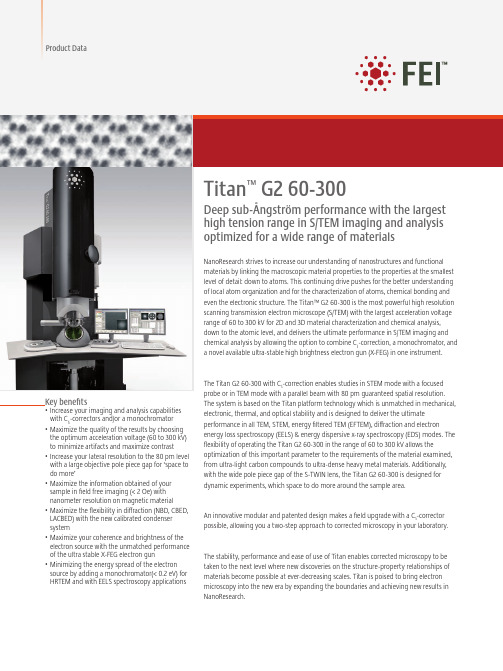
NanoResearch strives to increase our understanding of nanostructures and functional materials by linking the macroscopic material properties to the properties at the smallest level of detail: down to atoms. This continuing drive pushes for the better understanding of local atom organization and for the characterization of atoms, chemical bonding and even the electronic structure. The Titan™ G2 60-300 is the most powerful high resolution scanning transmission electron microscope (S/TEM) with the largest acceleration voltage range of 60 to 300 kV for 2D and 3D material characterization and chemical analysis, down to the atomic level, and delivers the ultimate performance in S/TEM imaging and chemical analysis by allowing the option to combine Cs-correction, a monochromator, and a novel available ultra-stable high brightness electron gun (X-FEG) in one instrument.
web.xmlservlet、servlet-mapping配置

web.xmlservlet、servlet-mapping配置Servlet 常称为服务器端⼩程序,即运⾏在服务器端的程序,⽤于处理及响应客户的请求。
Servlet类是个特殊的java类,继承于HttpServlet。
---------------------------------------------------------------⽅法客户端通常只有GET和POST两种请求⽅式,Servlet为了响应则两种请求,必须重写doGet()和doPost()⽅法。
⼤部分时候,Servlet对于所有的请求响应都是完全⼀样的,此时只需要重写service()⽅法即可响应客户端的所有请求。
另外,HttpServlet还有两个⽅法:(1). init(ServletConfig config):创建Servlet实例时,调⽤该⽅法的初始化Servlet资源。
(2). destroy():销毁Servlet实例时,⾃动调⽤该⽅法的回收资源。
通常⽆需重写init()和destroy()两个⽅法,除⾮需要在初始化Servlet时,完成某些资源初始化的⽅法,才考虑重写init()⽅法,如果重写了init()⽅法,应在重写该⽅法的第⼀⾏调⽤super.init(config),该⽅法将调⽤HttpServlet的init()⽅法。
如果需要在销毁Servlet之前,先完成某些资源的回收,⽐如关闭数据库连接,才需要重写destory⽅法()。
---------------------------------------------------------------Servlet创建时机(1). 客户端第⼀次请求某个Servlet时,系统创建该Servlet的实例,⼤部分Servlet都是这种Servlet。
(2). Web应⽤启动时⽴即创建Servlet实例,即load-on-start Servlet。
---------------------------------------------------------------Servlet的⽣命周期(1). 创建Servlet实例。
- 1、下载文档前请自行甄别文档内容的完整性,平台不提供额外的编辑、内容补充、找答案等附加服务。
- 2、"仅部分预览"的文档,不可在线预览部分如存在完整性等问题,可反馈申请退款(可完整预览的文档不适用该条件!)。
- 3、如文档侵犯您的权益,请联系客服反馈,我们会尽快为您处理(人工客服工作时间:9:00-18:30)。
24
29. Click on Image selection Tool 30. Select the STEM map
25
31. In SumSpectra component shortcut, click on Integrate 32. Click on spectrum and click on Copy KLM Setup
19
22. Press Acquire
20
23. You can monitor the drift by clicking on Show hide Output window
21
24. Go to TIA full mode 25. In TIA menu, go to View > Periodic Table g
45
53. In Quantify tab, click on Quantify 54. Select parent spectrum-image; click OK; click OK
46
55. Select Window > Floating Windows > Color Mix
47
55. Select Window > Floating Windows > Color Mix
43
50. In EELS Quantification window, select elements of interest within the energy range 51. Click on ‘Label’
44
50. Select ‘Edge Setup’ tab in EELS Quantification dialog window 51. Input the experimental conditions (the collection angle is found in Titan UI help (F1) > Operation > EELS Analysis > EELS Acceptance Angles 52. For each edge, adjust the position of the background and signal window
48
56. Select images and select color
22
26. In periodic table, select ROI tab and double click on all the elements of interest (e.g. Zn, O, C) )
23
27. Close the periodic table 28. Click on a spectrum and on TIA top tool bar, click on Copy KLM setup p p py p
17
20. In Experiments > Settings, define the experiment’s conditions
18
21. press 'Add markers' and position the map box (orange) and the drift correction box (y (yellow) )
26
31. To map an element, click on the Energy Window Tool 32. Select a window for background: typically, larger than signal window and about 5eV before the edge
33
39. Click on the map and press CTRL+C to copy; right-click on the map and select Paste Down; double-click on the new map, select Display tab, and check Show Legend
9
10. Set Preview to 0.1 and press Preview
10
11. In DM, go to EELS > Compute Thickness > Log-ratio (relative); thickness < 1 mfp is recommended
11
12. in PEELS CP, set search time to 0.1 (same as in Autofilter > Preview)
5
5b. Alternatively to step 5, you may enter the energy corresponding to the ZLP position, enter it in AutoFilter CP > Energy Shift, p gy press Enter, and Align ZLP g
13
14. Enter the Energy Loss of the lowest energy edge (e.g. N: 401eV); check that the Energy range [eV] encompasses all elements of interest NB. you can change the range by changing the dispersion; y may have to adjust the y g g y g g p you y j ZLP again
35
41. Rearrange the display
36
42. Run SerViewer.exe; find the .emi file containing the spectrum image
37
43. Export as .txt + .dat
38
44. In DM, select TIA SI > Import TIA Spectrum Image
27
33. Right-click on spetrum, and select Edit Background
28
34. Select the energy window and press OK
29
35. Move the background window left and right and make sure the background subtraction does not change significantly; also check that the edge signal decays back to zero
6
6. In DM, check cinema mode, and Start View
7
7. Adjust FX, FY, SX, SY: double-click on the corresponding adjustment in FilterControl and move the mouse left and right to make the ZLP as thin and vertical as possible; click again to accept the change or press Esc to cancel
EELS Map step-by-step
erwan.sourty@ f
Confidential
1. Load FEG Register 2. Look for a suitable area
2
3. Adjust magnification and focus / stigmate STEM image 3. In Filter CP switch to Spectroscopy p py
3
3b. you can use the focus dow so that the beam does not damage or contaminate the specimen too q p quickly; also Blank the beam when not observing y g
30
36.Select the signal with the energy window tool
31
37. In Unary processes, click on Extract Map/Profile
32
38. Double click on the map and in the Image/Display Properties dialog window change Name and Style as wished
4
4. Adjust Search time to 0.05s and press Search; lift flu screen (be careful not to saturate the GIF CCD!) 5. In Filter Control, set Slit Width to 0 eV, double click on Adjust and move the mouse left j and right to shift the ZLP to 0eV
16
18. Stop View, uncheck Cinema mode 19. Start STEM > Preview and keep scanning until step 22; If mapping an interface, adjust the STEM rotation so that the interface is either horizontal or vertical