Getein1100产品应用推介书
安捷伦1100液相色谱仪的使用说明书

*4 带seal-wash的 1100 要配制90%水+10%异丙醇 以每分2—
3滴的速度虹吸排出 溶剂不能干涸
5 其它主意事项见说明书 或由现场工程师介绍 维护知识
1 为什么溶剂和样品要过滤?
溶剂和样品过滤非常重要 它会对色谱柱 仪器起到保护作用 消除由于 污染对分析结果的影响 色谱柱 由于填料颗粒很细 色谱柱内腔很小 溶剂和样品中的细小颗粒 会使色谱柱和毛细管容易堵塞 仪 器 溶剂和样品中的细小颗粒会增加进样阀的堵塞和磨损 同时也会增 加泵头内的蓝宝石活塞杆和活塞的磨损 样品过滤头的类型 30mm内径 适用于大进样量的过滤 由0.2µm和0.45µm两种规格,材料有纤 维素,醋酸纤维,聚四氟乙烯 处理样品体积少于50µl 13mm内径 适用于范围广的过滤 由0.2µm和0.45µm两种规格,材料为纤维
13 从 Run control
菜单中选择 Sample
info 选项 如上图所示 输入操作者名称 在 Data file 中选择 Manual 或 Prefix
区别: Manual--每次做样之前必须给出新名字,否则仪器会将上次的数据覆盖掉 Prefix—
在Prefix
框中输入前缀 在Counter
(3) 单击Ok. (4) 从 Report 菜单中选择 Print
report 则报告结果将打印到屏幕上 如想输出到打印机上 则单击Report 底部的 Print 钮
(四) 关机:
关机前 用 100%的水冲洗系统20分钟 然后用有机溶剂冲洗系统10分钟 如ACN 然后关泵 适于 反相色谱柱 [正相色谱柱用适当的溶剂冲洗]
如图所示: “Optical Unit Temperature”---若环境温度控制在 2 ,设定为Off, 若环境温度不稳定,则设定光学单元温度为高于环境温度5度,以防样品在池中沉淀 Peak width ---大多数分析设为4S 只有在高速分析下设为更短 Automatic recycling after analysis --- 在不进行分析时可以让流动相循环 节省流动相 检测器连续运行 可随时投入使用
Intersleek 1000三组份不沾污涂料说明书

一种三组份不沾污涂料。
产品概述作为Intersleek 1000涂层体系中的面漆使用。
用于新造船以及维修和保养。
预期用途BXA100-白色, BXA101-灰色, BXA102-蓝色, BXA107-红色, BXA109-黑色72% ±2% (ISO 3233:1998)150 微米干膜厚 (208 微米湿膜厚)在 150 微米干膜厚时理论涂布率为 4.8 米²/公升,允许适当的损耗系数无气喷涂, 刷涂, 辊涂产品信息体积固体份标准膜厚理论涂布率施工方法面漆/光泽有光乙组份(固化剂)BXA103 (乙组分), BXA104 (丙组分)。
混合比例甲组份:乙组份:丙组份 = 7.4:1.6:1.0(体积比)闪点甲组份 41°C; 乙组份 30°C; 混合后 32°C; 丙组份 28°C 熟化时间不需要复涂数据-见“限定”一节底材温度颜色干燥资料10°C 15°C 25°C 35°C 温度在10°C 和20°C之间时,下水前的间隔可减少至24小时,条件是船舶在下水后必须至少停泊2天。
注:表干 [ISO 9117/3:2010]7 小时 6 小时 3 小时60 分钟 硬干 [ISO 9117-1:2009]9 小时8 小时 5 小时 2 小时 下水前48 小时36 小时20 小时17 小时 混合后施工时间120 分钟100 分钟60 分钟30 分钟复涂下列产品时10°C15°C25°C35°C最小最大最小最大最小最大最小最大有关复涂建议,请向贵处的国际油漆 (International Paint) 代表咨询。
注:法定数据挥发性有机化合物挥发性有机化合物值是典型值,仅提供用来作为参考。
它们可能会随着诸如颜色和常规制造误差之类因素的改变而发生变化。
GODEX 1100使用说明书
ᙆѓԴ͜٫:வ݊͠類ٙ༟ৃ産ۜ,ί֢ИٙᐑྤʕԴࣛ͜,̙ঐึிϓ࢛᎖ʍᓔ,ίவ၇ઋ䀒ɨ, Դ͜٫ึࠅӋڕ՟ݔԬቇٙ࿁ഄ.
此为C lass A产品,在生活环境中,该产品可能造成无线电干扰,在这种情况下,可能需要用户对其 干扰采取切.................................................................................................................. 3 1-1. 简介 ..........................................................................................................................................................3 1-2. 系列机种 ..................................................................................................................................................3 1-3. 全机器材 ..................................................................................................................................................3 1-4. 规格说明 ..................................................................................................................................................4 1-5. 通讯埠规格...............................................................................................................................................6 1-6. 条码机标准配备零件图示.......................................................................................................................7
ScreenBeam 1100无线显示接收器快速入门指南说明书
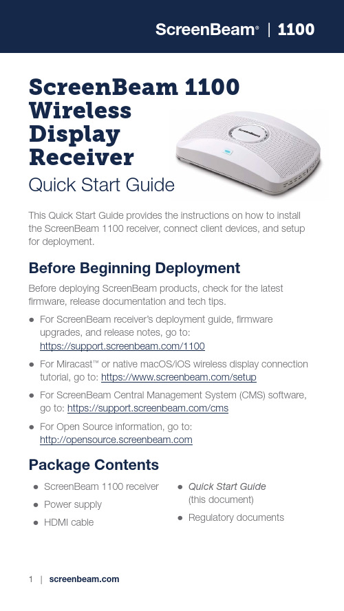
1100 ScreenBeam 1100 WirelessDisplayReceiverQuick Start GuideThis Quick Start Guide provides the instructions on how to install the ScreenBeam 1100 receiver, connect client devices, and setup for deployment.Before Beginning DeploymentBefore deploying ScreenBeam products, check for the latest firmware, release documentation and tech tips.z For ScreenBeam receiver’s deployment guide, firmware upgrades, and release notes, go to:https:///1100z For Miracast™ or native macOS/iOS wireless display connection tutorial, go to: https:///setupz For ScreenBeam Central Management System (CMS) software, go to: https:///cmsz For Open Source information, go to:Package Contentsz ScreenBeam 1100 receiver z Power supplyz HDMI cable z Quick Start Guide (this document)z Regulatory documentsIntroductionThe ScreenBeam 1100 allows presenters with Windows 10, macOS, iOS, or Android device to wirelessly display without requiring any apps. ScreenBeam 1100 offers a variety of secured network modes to support connection from the internal users on different subnets and external guest users.Overview of Network ModesScreenBeam 1100 supports local Wi-Fi, Wi-Fi Miracast, and wireless display over existing infrastructure network. T wo or more modes can operate concurrently to support various scenarios where both internal and guest users could simply connect and project.1100Local Wi-FiThe ScreenBeam Wi-Fi mode provides the simplest form of network for client devices to connect and project. In this mode, user needs to connect the client device Wi-Fi to the ScreenBeam Wi-Fi and then select the receiver to mirror. This mode is ideal for guest client devices that needs wireless display and or Internet access. Internet is available if the ScreenBeam receiver is connected to the existing network, wired or wireless if bridge mode is enabled. Mobile device with cellular service can access the Internet and wireless display if bridge mode is disabled.Figure 1 Client device wireless display by connecting to ScreenBeam’s local Wi-FiNote: ScreenBeam Wi-Fi is fully secured and manageable via ScreenBeam CMS with options to tune the wireless power transmission, channel and encryption type.Wi-Fi MiracastThe Wi-Fi Miracast mode allows compatible Wi-Fi Miracast devices to connect directly to ScreenBeam, even when connected to an infrastructure wireless network. Miracast is commonly available on Windows 10/8.1 and Android 4.4 (and later) devices since 2015. Users can enjoy wireless display and Internet access if the client device is already connected to Wi-Fi.Figure 2 Miracast client device wireless display by connecting to ScreenBeam’s Wi-Fi Miracast network1100Wireless Display over existing LAN ScreenBeam 1100 can be connected to the existing wireless or wired network and supports wireless display for client devices on either network. This is a common setup to support client devices that needs access to network resources. Additional port and network configurations may be required for this mode to work seamlessly.Figure 3 Client device wireless display over existing infrastructure networkScreenBeam 1100 can be connected to two different networks concurrently. This dual-network feature allows the flexibility of supporting wireless display for either staff (on internal network) or visitors (on guest network). Refer to the deployment guide for more details.Minimum RequirementsSystem RequirementsClient device from 2015 or newer with one of the following operating systems:z Windows 10 build 1709 (and later)z macOS X 10.10 (and later)z iOS 11 (and later)z Android 4.4 (and later) with MiracastNetwork RequirementsFor wireless display over the existing wireless network or LAN:z Ethernet: 100BASE-T 10/100 connection(1 Gbps is recommended)z Wireless: 802.11ac (5GHz is strongly recommended)z Multicast DNS (mDNS) support is required for iOS and macOS native screen mirroring to auto-discover ScreenBeamz Required portsz5353 (UDP) for Multicast DNS (mDNS) discoveryz7100 (TCP and UDP) for macOS, iOS andWindows 10 mirroringz7250 (TCP) for Miracast over LAN data streamz18000-18009 (TCP) for macOS and iOS AV dataNote: Additional network configuration is not required forWi-Fi Miracast enabled device to connect. Verify Group Policy and firewall settings to allow Wi-Fi Direct groups or hosted networks.1100Setup Requirementsz ScreenBeam 1100 receiverz Display with an available HDMI inputz(Optional) Touchscreen with USB touch cablez An ethernet network connection with DHCP IP or aWi-Fi routerNote: This is used for wireless display over LAN and management.z ScreenBeam wireless display appNote: Not required for Windows 10/8.1, macOS, and iOS with native screen mirroring support.Figure 4 ScreenBeam 1100 setup1. Place the receiver next to the display.2. Connect one end of the provided HDMI cable to the receiver’sHDMI port and the other end to an available HDMI port on the display.Note: For VGA connection details, refer to the ScreenBeam 1100 User Guide.3. Optional: If the display has USB HID touch capability, insertthe HID USB connector into a USB port of the ScreenBeamreceiver. (USB cable is not included)4. Connect the receiver’s power supply to the receiver’s powerport, then to an electrical outlet.5. Optional: Connect one end of the Ethernet cable to thereceiver’s Ethernet port and connect the other end to thenetwork switch with DHCP IP. (Ethernet cable is not included).Note: Refer to section B for more information on setting upa network connection.6. Turn on the display and switch to the corresponding inputconnected to the receiver.7. Wait for the Ready to Connect screen to appear on the display.1100 ScreenBeam requires network connection for various purposes, such as wireless display over LAN support and management of the receiver. ScreenBeam can be connected to the network via wired or Wi-Fi connection.Wired ConnectionIf ScreenBeam is connected to a DHCP-enabled network, the Ready to Connect screen will show the IP address assigned to the ScreenBeam.Wireless Connection or Static IP AddressThis requires additional steps to configure the receiver with the proper network credentials. Refer to Section D for instructions on how to setup the ScreenBeam receiver.Using a wired connection with DHCP IP is recommended for initial testing.This section provides the instructions on how to connect to ScreenBeam using the native screen mirroring from the most common operating systems.Refer to /setup for details and instructions for all other operating systems.Note: The web page will display the instructions based on the client-device OS. Use the links at the bottom of the web page to select OS-specific instructions.Connect Using Local Wi-Fi1. Connect the client device’s Wi-Fi to the wireless network (APSSID) as shown on the TV display. Windows 10/8.1 or Android with Miracast can skip to Connect Using Wi-Fi Miracast section.2. Enter the password for the wireless network.screenbeam is the default password.3. Select the ScreenBeam receiver name as shown on the TV display.z For Windows 10Select Connect from the Action Center by swiping from right or simultaneously pressing the Windows key and K.z For iOS or macOSConnect with from the menu bar or control center.4. Enter in the PIN if required. If the PIN code is not displayed, trythe hidden PIN 1234.5. Select duplicate or extended screen mode if prompted.6. If the display has touch functionality, Windows 10 devices cantake advantage of the touch and inking feature by selectingAllow touch…. (Refer to section F for more details.)Note: To disconnect, return to the screen mirroring menu and select mirroring off.1100Connect Using Wi-Fi Miracast1. Select the ScreenBeam receiver name as shown on theTV display.z For Windows 10Select Connect from the Action Center by swiping from right or simultaneously pressing the Windows key and K.z For AndroidSelect the Screen Mirroring option from the quick accessmenu and follow the connection instructions.2. Enter in the PIN if required. If the PIN code is not displayed, trythe hidden PIN 1234.3. Select duplicate or extended screen mode if prompted.4. If the display has touch functionality, Windows 10 devices cantake advantage of the touch and inking feature by selectingAllow touch…. (Refer to section F for more details.)Note: Some Android devices do not support PIN and will fail to connect. Refer to section D below for instructions on how to configure ScreenBeam and disable PIN enforcement. | 11Connect Using theExisting Wireless Network or LAN1. Connect the ScreenBeam receiver to a known network whereyour client device can communicate over Wi-Fi.2. Verify the receiver obtained an IP address (shown on the Readyto Connect screen).3. Connect the client device to the same network as ScreenBeamreceiver4. Select the ScreenBeam receiver name as shown on theTV display.z For Windows 10Select Connect from the Action Center by swiping from right or simultaneously pressing the Windows key and K.z For iOS or macOSConnect with from the menu bar or control center.5. Enter in the PIN if required. If the PIN code is not displayed, trythe hidden PIN 1234.6. Select duplicate or extended screen mode if prompted.7. If the display has touch functionality, Windows 10 devices cantake advantage of the touch and inking feature by selectingAllow touch…. (Refer to section F for more details.) Congratulations!The display is now enabled for wireless screen mirroring.12 | 1100 ScreenBeam 1100 can be configured by using the ScreenBeam CMS software or accessing the ScreenBeam’s local management interface (LMI).Using ScreenBeam CMS SoftwareScreenBeam Central Management System (CMS) is a highly recommended complimentary tool for multi-unit deployment, configuration and administration.1. To obtain CMS software and the CMS User Guide, go to:https:///cms.2. Refer to the CMS User Guide for setup instructions.Note: Access to the LMI is prohibited by default if ScreenBeam 1100 is connected to ScreenBeam CMS for management. This option can be changed in the receiver’s settings.Figure 5Receivers managed by ScreenBeam CMS | 13Using Local Management on ScreenBeamThe Local Management Interface can configure and update a single ScreenBeam. There are three methods to access the LMI: Method 1: ScreenBeam Local Wi-Fi Network1. Connect the client device’s Wi-Fi to the wireless network(AP SSID) as shown on the TV display.2. Enter the password for the wireless network.screenbeam is the default password.3. The Ready to Connect screen on the display will show theassigned IP address of the ScreenBeam.4. Enter the assigned IP address into the web browser of a PC orApple device.z If the receiver is not connected to an existing wireless network or LAN, its IP address is 192.168.26.1.z If the receiver is connected a network, the IP address can be identified on the Ready to Connect screen.5. The browser may give an error stating “The connection or siteis not secure or private.” Manually accept the connection asfollows:Chrome browser: click Advanced, then click Proceed.Edge/IE browser: click Details, then Go on to the webpage (not recommended).Firefox browser: click Advanced, then click Add Exception, then click Confirm Security Exception.6. When the ScreenBeam management page appears, enter theUsername Administrator and Password screenbeam (both case-sensitive).14 | 1100Method 2: Network Connection via DHCP1. Using a shielded RJ-45-terminated Cat5e or better Ethernetcable, connect the ScreenBeam Ethernet port to a DHCP-enabled network.2. The Ready to Connect screen on the display will show theassigned IP address of the ScreenBeam. Enter this address into the web browser of a PC or Apple device on the same network as the ScreenBeam.3. Follow the directions from Method 1 from Step 5 on.Method 3: Wireless P2P Direct Connection1. Using a Windows 10/8.1 device, connect the device to theScreenBeam per section B above.2. Once connected, use a web browser and enterhttps://192.168.16.1 to access the LMI.3. Follow the directions from Method 1 from Step 5 on. | 15Under the Device Configuration PageAssign new Device Name1. From the Device Name Access option, select Enable.2. Select the Device Name text box, then enter a new name(example: Conference TV).Note: Each receiver should have a unique name; this makes it easier for users to identify and connect to the correct display. Supported naming characters areA-Z, a-z, 0-9, -, _.Change the Administrator’s Password1. Select the Administrator Password text box and enter thenew password.2. Select Apply/Save button to save any changes.Under the Features PageConfigure Force PIN Pairing OptionBy default, the Force PIN Pairing option is Enabled and the PIN code is generated randomly. A unique PIN is will be generated each time a new user/device attempts to connect. To change the PIN pairing type or PIN code:1. Select either ON to force PIN or OFF to not force PIN uponconnection.2. If Force PIN Pairing is ON, select either Each connection orFirst connection only.16 | 11003. Select Random or Static for PIN code generation.4. If Static, then enter PIN of choice. Keep note of the new PIN foruser distribution.Note: For eight-digit PIN option, only the first seven digits of the PIN can be set in configuration; the eighth digit will be automatically chosen by the ScreenBeam and appended to the first seven.5. Select Apply/Save button to save any changes. Configure HDMI/VGA PortPower ManagementBy default, ScreenBeam is designed to display the Ready to Connect screen continuously. To extend display life and/or reduce power consumption:1. Select either Screen Saver or Display Off.2. Enter a desired time for setting to take effect.3. Optional: Select a Wake up mode.4. Select Apply/Save button to save any changes. | 17ScreenBeam 1100 supports wireless inking and touch with Windows 10 Miracast for collaboration using a touchscreen display. Users can project their preferred Windows 10 application and take notes on the touchscreen; the notes appear directly on the client device. System RequirementsOS: Windows 10 build version 1709 (or later)CPU: 5th Gen Intel Core i-Series 5xxx or AMD equivalent(or better)RAM: 4 GB or moreSetup Requirementsz Interactive touch display or projectorz USB Type-A to Type-B/A cable(depending on the touchscreen type)Supported Featuresz Support USB HID display, projector, or whiteboardz Up to 20-point touchz Up to four simultaneous passive pensz Up to two simultaneous active pensSupported features may require compatible touchscreen and or application. Works best with InGlass™ Technology enabled display. Refer to the online compatibility list at:https:///touch/compatibility18 | 1100Setup and Instructions1. Connect the USB Type-A end to the ScreenBeam 1100receiver’s USB port.2. Connect the USB Type-B/A end to the USB Touch input on thedisplay or projector.Note: If the display provides more than one touch output, make sure the USB Type-B/A end is connected to the same touch output as the HDMI input.3. Connect Windows 10 device to ScreenBeam 1100 (seeinstructions in section C).4. Start using the display by touching the screen. Launch an appand draw using finger or pen.Please read the deployment guide for best practices and tips before placing the ScreenBeam 1100 to the site for users.1. Unplug the power supply and HDMI cable from ScreenBeam1100 receiver.2. Move the receiver to its permanent location.Note: Access to a wired or wireless LAN connection isrequired.3. Plug the HDMI cable to the receiver and the display.4. Plug in the receiver’s power supply.5. Switch the display to the correct input and verify the Ready toConnect screen appears.6. Verify the ScreenBeam 1100 obtains a valid IP address.Note: By default, ScreenBeam shows all of the receiver’s information on screen for ease of troubleshooting. The information can be configured to be hidden from the management interface or via CMS. | 19z Wi-Fi Internet is limited when connecting to ScreenBeam local Wi-Fi unless ScreenBeam is connected to the network and bridge mode is enabled.z If ScreenBeam is connected to the existing network, some existing access points and or controllers (i.e. Meraki or Cisco) may flag it as a rogue AP and restrict the client from connecting. Consult with the network administrator to flag ScreenBeam as a friendly access point.z Windows 10 build 1803 (and earlier) do not support wireless display PIN on Miracast over LAN. The connection will fall back to establishing the Miracast over Wi-Fi Direct path. Support InformationFor FAQs, troubleshooting tips and support, visit:https://To open a ticket for support, visit:https:///ticketWebsite: This product is intended to be supplied by a Listed Direct Plug-In Power Unit marked “Class 2”, Listed Power Adapter or DC power source marked “L.P.S.” (or “Limited Power Source”) and rated12Vdc, 3A minimum.US SKU: Model # CDS036-W120U.International SKU: Model # ATS036T-W120V.Made by ScreenBeam.PN: 0530-0838-002© 2020 All rights reserved. ScreenBeam and the ScreenBeam logo are registered trademarks owned by ScreenBeam Inc. All other names are properties of their respective owners. Specifications subject to change without notice. 0406200-v8。
EASYGET 手持式光纤端面检测仪使用说明书

EASYGET 手持式光纤端面检测仪1简 介致用户:尊敬的维度科技产品用户,感谢您选择使用EASYGET 产品。
EASYGET 产品质量优,性能佳。
为充分发挥本产品的最大性能,请在使用前仔细阅读本手册,并按照说明书的步骤操作,在阅读本手册后,请妥善保存,以便随时参考。
使用时无论有任何问题请按照附件的电话、地址联系,我们时刻恭候为您服务!以下符号为本手册中的重要提示信息。
请务必仔细阅读。
注意事项1. 有关本手册的任何更改将不做另行通知,敬请谅解。
2. 本手册的内容是本着准确无误的目标进行制作的。
但是,如果发现有不清楚、错误或含糊的内容,请使用手册最后留的联系方式随时进行沟通。
3. 如有缺页或装订错误,本公司予以更换。
有关产品的注意事项1. 注意保持视频显微镜端面的清洁,做到无脂、无污染。
2. 保持手持式显示器的清洁,防止 TFT 液晶屏被尖锐物划伤、或者被重物挤压。
3. 长时间不用时最好将其放置在仪器箱内。
4. 使用前请检查手持式显示器的电量,如果只有一盏灯亮请充电后再使用。
EASYGET 手持式光纤端面检测仪 2产品保修本公司对本产品原则上承担以下保修。
自购买后1年以内。
在保修期内,因公司的责任造成的故障,本公司将无偿地进行修理或部件更换。
即使在保修期内,由于下列原因造成的故障不在本公司保修范围内。
1) 错误操作导致的设备损坏; 2) 非本公司维修人员进行修理或改装; 3) 仪器以外的原因造成的故障;4) 在高温潮湿、有腐蚀性气体、剧烈振动等恶劣条件下使用;5) 遭遇火灾、地震等天灾以及由放射性物质、有害物质造成的污染以及战争、暴动、犯罪等其他不可抗力时; 6) 消耗品及易耗品零部件。
EASYGET 手持式光纤端面检测仪3本手册的结构本章阐述各个部件的名称和功能。
本章阐述设备的安装与连接。
本章阐述设备的性能特点及基本操作。
EASYGET 手持式光纤端面检测仪 4目 录简 介 ................................................................................................................ 1 产品保修 ............................................................................................................ 2 本手册的结构 ..................................................................................................... 3 目 录 ................................................................................................................ 4 1 概要 ............................................................................................................... 6 1.1检查包装 .................................................................................................................... 6 1.1.1设备主机 ............................................................................................................ 6 1.1.2附件 ..................................................................................................................... 6 1.2各部件名称及功能 ................................................................................................... 7 1.2.1设备正面 ............................................................................................................ 7 1.2.2显示器正面 ........................................................................................................ 7 1.2.3显示器侧面 ........................................................................................................ 8 1.2.4接口 ..................................................................................................................... 8 2 设备安装 ........................................................................................................ 9 2.1部件安装 .................................................................................................................... 9 2.2设备连接 .................................................................................................................... 9 2.2.1与连接器连接 .................................................................................................... 9 2.2.2与手持式显示器连接........................................................................................ 9 2.2.3与台式显示器连接 .......................................................................................... 10 3 硬件基本操作 ................................................................................................11 3.1硬件性能特点 .......................................................................................................... 11 3.2性能指标 .................................................................................................................. 11 3.3硬件操作 .................................................................................................................. 12 3.3.1手持式显示器连接使用方法 . (12)EASYGET 手持式光纤端面检测仪53.3.2台式显示器连接使用方法 ............................................................................. 12 3.3.3 PC 机连接使用方法........................................................................................ 13 3.3.4设备充电方法 .................................................................................................. 13 附录 ..................................................................................................................14 记录 (14)EASYGET 手持式光纤端面检测仪61 概要1.1检查包装从包装中取出产品,并检查是否包含以下部件。
S1000推介资料0810版 [只读] [兼容模式]
![S1000推介资料0810版 [只读] [兼容模式]](https://img.taocdn.com/s3/m/b82d39cf050876323112129e.png)
S1000/S1000B低CTE中Tg板2005年3月25日p S1000/S1000B主要内容:1、背景介绍 2、行业同类产品一览表 3、我司产品介绍 3 我司产品介绍 4、PCB应用考察 5、S1000材料的使用定位 6、S1000注意事项 6 S1000注意事项 6、使用建议®p S1000/S1000B一、背景介绍在PCB终端的可靠性测试 中,以日本为代表越来越多 的客户采用冷热循环测试, 的客户采用冷热循环测试 多次试验表明我司常规产品 无法满足这种测试要求,如65℃ --125℃ /1000 l 因 125℃ /1000cycle。
因 此急需开发性能更为优越的 产品满足此要求。
®p S1000/S1000B二、行业同类产品介绍PropertiesTg (DSC) ℃ Td (TGA) ℃ Peel Strength(1oz) N/mm DK@1MHz Df@1MHz Thermal stress@288℃ solder dip) sec. T260 (TMA) min T288 (TMA) min Z-CTE (<Tg) g ppm/℃ Z-CTE (>Tg) ppm/℃ Z-CTE(50 260℃) Z-CTE(50~260℃) % CAF resistanceShengyi S1000 150 335 1.4 14 4.7 0.011 0 011 >100 >60 10 43 245 33 YesIsola IS400 145-150 325 >1.3 13 4.8-5.1 0.0130.015 >10 60 10 38 200 3.0 YesNelco N4000-7 155 330 1.3 13 4.5(RC50%) 0.018(RC50 %) N/A 16 N/A 50 260 3.7 YesHitachi N/A N/A N/A N/A N/A N/A N/A N/A N/A N/A N/A N/A N/AITEQ IT158 155 345 1.6 16 4.8 0.016 0 016 >10 >60 >20 40 240 3.3 YesTUC TU-622-le 150 340 1.4-1.9 14 19 4.6(RC50%) 0.014(RC50 %) >60 >60 15 N/A N/A 3.4 Yes®p S1000/S1000BIPC-4101B与我司产品标准IPC-4101B IPC-4101B/ 99(含填料 T >150℃) IPC 4101B/ 99(含填料,Tg>150℃) IPC-4101B/ 101(含填料,Tg>110℃) IPC-4101B/ 121(无填料,Tg>110℃) (无填料, g ) IPC-4101B/ 124(无填料,Tg>150℃) IPC-4101B/ 126(含填料,Tg>170℃) IPC-4101B/ 129(无填料,Tg>170℃) 产品对应 S1000/S1000-2 S1000/S1000 2 --S1141KF S1170 S1000-3 S1180®p S1000/S1000B三、产品介绍产品型号/Dsg. 产品性能表编号/Specification Sheet# 产品描述/Description 产品应用/Applications 无铅兼容性/Lead Free Compatible 耐离子迁移能力/Anti-CAF 环境管理要求/ROHS & WEEE 无卤兼容性/Halongen Free 热冲击可靠性/Thermal Shock Resistance 玻璃化转变温度/DSC Tg(℃) 热分解温度/Decomposition Temp(℃) 热分层时间/T-260(Minutes) 热分层时间/T-288(Minutes) Z轴热膨胀系数/Z-CTE before Tg(PPm/℃) Z轴热膨胀系数/Z-CTE after Tg(PPm/℃) Z轴热膨胀率/Z-CTE under 50℃ to 260℃(%) S1000/S1000B IPC-4101/99,101 Phenolic Cured Filled Tg150 High Performance &Lead Free Compliant Yes Yes Yes No High(Q1000&IST) 155 335 60 11 40 240 3.3%®p S1000/S1000B ●中TgMid Tg :Tg(DSC) =159.06℃/157.68℃样品: 大小: 方法: 注释: S10009 25.6000 mg DSC210 周期1:蓝色曲线;周期2:红色曲线DSC目录: D:\检验结果\DSC检验结果\开发室\曾宪平 运行日期: 2005-03-30 16:54 仪器: DSC Q10 V9.0 Build 2750.0 00-0.1热 (W 流 /g)-0.2-0.3157.68°C(I) 159.06°C(I)-0.480向上放热100120140温度(°C)160180200Universal V4.1D TA Instruments®p S1000/S1000B ●热分解温度 Td (TGA,5% Wt Loss ,10 ℃/min)=335℃100––––––– S1000 1,6(10.00 °C-N2).001 –––– S114190335 ℃ 5.00%LossWeight (%)Lead-free FR-480DICY cured FR-47060 100200300400500600700Universal V2.6D TA InstrumentsTemperature (°C)®p S1000/S1000B ●热分层时间 De-lamination Time(TMA, 10 ℃/min)Normal FR-4 T260 T288 15 min 2 minS1000 >60 10®p S1000/S1000B ●热分层时间T260 T260(TMA:10℃/min )样品: S10009 大小: 1.0459 mm 方法: T-260TMA目录: D:\检验结果\TMA测试结果\技术开发\曾宪平 运行日期: 2005-03-31 08:04 仪器: TMA Q400 V7.0 Build 804030T260分层时间>60min尺 变 (µm) 寸 化2010®0 10 20 30 40时间(min)50607080Universal V4.1D TA Instrumentsp S1000/S1000B ●热分层时间 T288( TMA:10℃/min )样品: S10009 大小: 1.0379 mm 方法: T-288TMA目录: D:\检验结果\TMA测试结果\技术开发\曾宪平 运行日期: 2005-03-30 15:27 仪器: TMA Q400 V7.0 Build 8026.44min 287.05°C37.54min40T288分层时间: 11.10min 尺 变 (µm) 寸 化2005101520时间(min)253035Universal V4.1D TA Instruments®p S1000/S1000B ●热膨胀系数 CTE (Coefficient of Thermal Expansion) ( p ) Items It Before Tg Z-axis CTE After Tg 30-260℃ 30 260℃ Rate (50-260℃) X/Y-axis CTE Actual l A t l value 37~45 220~240 130~140 130 140 3.3% 12~16®Units U itμm/m℃p S1000/S1000B ● Z轴热膨胀系数 Z-Axis CTE (Coefficient of Thermal Expansion) ( )样品: S1000 大小: 2.2337 mm 方法: T-288TMA目录: D:\检验结果\TMA测试结果\技术开发\曾宪平 运行日期: 2005-04-20 18:16 仪器: TMA Q400 V7.0 Build 8080259.78°C60259.78°C 259 78°C Alpha=228.1µm/(m·°C)尺 变 (µm 寸 化 )4064.60µm 2.892%20175.16°C 130.88°C Alpha=43.55µm/(m·°C) 29.62°C 50.07°C60 80 100 120 140温度(°C)040160180200220240260Universal V4.1D TA Instruments®p S1000/S1000BS1000 Dk、Df值1MHz Type 7628(46%) 2116(55%) 1080(67%) 106(73%) Dk 4.72 4.54 4 54 4.23 4.11 Df 0.0152 0.0201 0 0201 0.0219 0.0229 Dk 4. 31 4.04 4 04 3.76 3.64 1GHz Df 0.0118 0.0135 0 0135 0.0163 0.0186®p S1000/S1000B四、产品性能考察1、Q1000测试 2、CAF测试 3、耐热冲击性 3 耐热冲击性 4、高压锅测试 5、高温高湿考察®p S1000/S1000B ●冷热冲击实验Q1000 Thermal Shock Q1000Thermal shock test condition:A)Pre-treat: 125℃/2hour in the oven. oven B)Thermal shock condition: -40℃(30min)~temp. change(<2min)~+125℃(30min), 1000cycles.Chart Ch rt 1 R i t n Resistance change r t h n rate10.00%Resistance Change Rate(%)8.00% 8 00%6.00%4.00%2.00%0.00%0pre-treat1002003004005006007008009001000-2.00%Cycles1 2 3 4 5 6®p S1000/S1000B ● 孔壁切片分析(Q1000测试后) Micro-section after Q1000X200 micro-sectionX50 micro-section®p S1000/S1000B ●耐热冲击性 Thermal Shock Resistance Normal FR 4 l FR-4 Dipping@288/10sec→25 ℃ N Di i @288/10 25 cycles y 3 S1000 15Test condition: 288 ±5℃→25 ℃ /dipping; pp g; Construction: 8 layers (1oZ+7628+0.41/1+7628+0.41/1+7628+0.41/1+7628+1oZ) Sample size:50mm×50mm®p S1000/S1000B ●耐CAF性能测试 Anti-CAF TestS1000 R Resistanc ce(MΏ)35000 25000 15000 5000 0 100 200 300 400 500 600 700 800 900 1000Time(hr)Test condition:TH-to-TH,Pitch=0.8mm, ф=0.30mm 100V/40℃/92%RH®p S1000/S1000B ●高压锅测试 PCT( High Pressure Cooker Test) ( g ) Dipping@288℃/10 sec Normal FR-4 30 min 60 min 120 min OK OK NG S1000 OK OK OKPCT(E-105℃/105KPa)Test T t condition: 1.6mm(no cu )100*100 diti 16 ( )100*100mm,®p S1000/S1000B●高温高湿考察Water AbsorptionWater Absorption处理后热冲击S1000普通FR-4 80/90%,96h,>62次分层288/10s/次dip>63次分层288/10s/次,dip>61次分层Sample: 1.6mm(unclad )50mm*50mmp S1000/S1000B五、PCB应用考察1、改善焊盘起翘和树脂收缩问题整板厚度1.6mm,288 ℃/10S/3次S1000材料普通FR-4材料®p S1000/S1000B五、PCB 应用考察2、改善密集BGA 孔或散热孔爆板问题S1000材料®p S1000/S1000B五、PCB应用考察3、解决HDI埋孔眉毛裂问题用于生产HDI填埋孔试验,发现S1000能有效改善埋孔眉毛裂问题。
杜诺尔1100系列传输器产品说明书

E N G I N E E R I N G M A N U A LPatent Pending PinchDrive DesignClean Room CertifiedClass 100Industry-Best Product TransfersFast & Simple to Use Online ConfiguratorThe Industry’s Smallest Conveyor Designed to Fit in the Tightest Spaces!1100 SERIES CONVEYORSINDUSTRY LEADING TECHNOLOGY1100 SERIESThe Benefits of a Dorner 1100 Series ConveyorIndustry Ready• Clean Room Class 100 Certified for medical and pharmaceutical applications • T -Slot for ease and flexibility in mounting automation components or accessories • F DA Approved Belting Time Saving • D orner’s online configuration engineers simple or complex conveyors to meet your needs in minutes • T he industry leading tool delivers a complete 3D CAD Assembly model for instant validation of fit • D orner provides the industry's fastest deliveries• Backlit conveyor with an LED light is ideal for inspection and quality control• Provides a contrast between the product and conveyor belt for both visual inspection and vision system interface • Parts can be stopped directly over the lighted section or continue through uninterrupted• Unique design allows access to LED panel without removal of the belt for ease of use and light color changes•maintenance free operation• pinch drive for consistent performance • Drive is reversible, providing maximum flexibility in applications• Two halve design with one fastener per side allows cover to pivot for fast belt change • T-Slot for flexible mounting• Spring tensions belt around drive pulley for 180° of wrap• 32 mm (1.25 in) lagged urethane drive spindle• 19 mm (.75 in) frame height• 16 mm (.625 in) or 8 mm (.3125 in) diameter idler pulleys • Optimal size for handling and transferring of small parts • T-Slot for fast mounting of accessories • Flush edge design to fit into tight spaces• Cam belt tracking conveyor extends only 19mm (3/4 in) beyond frameMid DriveEnd DriveBELTED CONVEYOR FEATURES1100 SERIESOPTIONAL8 mm (.3125 in) NOSE BARON ONE OR BOTH ENDSCAM BELT TRACKINGFDA APPROVED BELTING(LOW, MEDIUM &HIGH FRICTION)16 mm (.625 in) ROLLERCOVEREXTENDS ONLY 19 mm (.75 in) BEYOND FRAMEMID DRIVEMOVEABLE ALONGFRAME AND REVERSIBLE BELT DIRECTION19 mm (.75 in) FRAME HEIGHTTHE SIZE OF A PENNYFLUSH EDGE DESIGNTO FIT INTO TIGHT SPACESPATENT PENDING TWO HALVE DESIGNFOR QUICK BELT CHANGEMid DriveEnd DriveFOR FLEXIBLE MOUNTING TO SURFACES32 mm (1.25 in) LAGGED AROUND DRIVE PULLEY FOR OVER 180° OF WRAPFLAT BELT END DRIVE1100 SERIESSpecifications• Loads up to 6.8 kg (15 lbs)• Belt Speeds up to 21 m/min (66 ft/min)• Belt Widths: 44 mm (1.75 in), 95 mm (3.75 in), 152 mm (6 in), 203 mm (8 in), & 254 mm (10 in)• Conveyor Lengths: 270 mm (10.63 in) to1,829 mm (72 in) in 3 mm (0.125 in) Increments • 25 mm (1 in) Diameter Drive Pulley • 16 mm (0.625 in) Diameter Idler Pulley• 8 mm (0.31 in) Diameter Nose Bar Option • (3) FDA Approved Belt Options: Low, Medium, & High Friction • M5 Drop in T-Nuts Available• 25 mm (1 in) & 51 mm (2 in) UHMW GuidesSide MountBottom MountFor part number information, see page 6OPTIONAL NOSE BAR TRANSFERRETURN ROLLERNote: Conveyor with side mount must be mounted at drive end location.FLAT BELT MID DRIVE1100 SERIESSpecifications• Loads up to 6.8 kg (15 lbs)• Belt Speeds up to 21 m/min (80 ft/min)• Belt Widths: 44 mm (1.75 in), 95 mm (3.75 in),152 mm (6 in), 203 mm (8 in), & 254 mm (10 in)• Conveyor Lengths: 283 mm (11.13 in) to 1,829 mm (72 in) in3 mm (1/8 in) Increments• 32 mm (1.25 in) Diameter Mid Drive Pulley• 16 mm (0.625 in) Diameter Idler Pulleys• 8 mm (0.31 in) Diameter Nose Bar Option One or Both Ends Type 1 Mount• (3) FDA Approved Belt Options: Low, Medium, & High Friction• M5 Drop in T-Nuts Available•25 mm (1 in) & 51 mm (2 in) UHMW Guides Array Type 2 MountFor part number information, see page 6PROFILE AND BELTING1100 SERIESDim = mm (in)* Note: See page 13 for detailed Chemical Resistance data.Belt SpeedStandard Belt Selection GuidePart Number ReferenceProfilesLow Side25 mm (1 in) UHMW High Side 2251 mm (2 in) UHMW High SideType 1 Mid Drive• Includes gearmotor mounting bracket, coupling, coupling guard and mounting hardwareA: 78 (3.07)• Includes gearmotor mounting bracket, coupling, coupling guard and mounting hardware• Includes gearmotor mounting bracket, coupling, coupling guard and mounting hardwareA: • Includes gearmotor mounting bracket, coupling, coupling guard and mounting hardwareA: WNote: Conveyor and gearmotor are not included in the mounting package and must be ordered separately.Note: Due to the wide variety of drive set ups and applications, point of installation guarding is the responsibility of the end user.GEARMOTORS1100 SERIESFixed SpeedVariable SpeedIndexing RepeatabilityBrushless DC gearmotors are capable of indexing up to 60 times per minute. Index repeatability is belt speed dependent.Some motors and gear reducers may normally operate hot to the touch. Consult factory for specific operating temperatures. Note: Dimensions = mm (in)Note: Due to the wide variety of drive set ups and applications, point of installation guarding is the responsibility of the end user.VARIABLE SPEED CONTROLLERS1100 SERIES Variable Speed ControllersNote: Dimensions = mm (in)Note: Due to the wide variety of drive set ups and applications, point of installation guarding is the responsibility of the end user.MOUNTING BRACKETS & ACCESSORIES 1100 SERIESMounting BracketsAccessoriesNote: Dimensions = mm (in)Note: Due to the wide variety of drive set ups and applications, point of installation guarding is the responsibility of the end user.TECHNICAL DATA AND CALCULATIONS1100 SERIES Regulatory Approvals:Conveyors:All Dorner 1100 Series standard conveyors (not including gearmotors and controllers) are CE approved. CE approval followsthe provisions of the following directives; Machine Directive 2006/42/EC, EU Low Voltage Directive 2006/95/EC, and EMC Directive 2004/108/EC. All conveyors are marked with the CE symbol on the Dorner serial number tag located on the conveyor frame. Contact the factory for the CE Declaration of Conformity.All Dorner 1100 Series standard conveyors (not including gearmotors and controllers) are designed and manufacturedin accordance with the restrictions defined in the “Restriction of Hazardous Substances” directive, citation 2002/95/EC, commonly known as RoHS. All conveyors are marked with the RoHS symbols on the Dorner serial number tag located on the conveyor frame.Gearmotors and Controllers:All Dorner 1100 Series gearmotors and controllers carry one or more of the following approvals. Products are not coveredby each approval. Please see the appropriate part number on the Gearmotor and controller charts located in this manual. In addition, regulatory symbols are located on the product information tags located on the product.1100 SERIESTECHNICAL DATA AND CALCULATIONSClean Room Certifications:The 1100 Series Conveyors are often used in clean room applications where the generation of particulates from the conveyor are a concern. In these applications the correct installation and application of the conveyor is critical to the proper running of the conveyor and minimizing the dust generated by the conveyor belt or modular belt. The end user must ensure that the conveyor belts are properly tracked and product accumulation is minimized to provide minimal dust generation.All of the 1100 Series products are designed and constructed to be used in clean room environments. The 1100 Series products have gone through third party testing and certification and are certified for use in ISO Standard 14644-1 Class 5 and Federal Standard 209 Class 100 Clean Room applications.Contact the factory for copy of the certification.Materials and Chemical Resistance:The 1100 Series Conveyors are designed to run in clean, dry environments. Any chemicals introduced to the application must be minimal and the conveyor cleaned on a regular basis. Chemical exposure should be limited to minimal exposure on the belt surface only. Excessive chemicals/debris will cause the conveyor pinch drive system to malfunction. Contact factory for added information.TECHNICAL DATA AND CALCULATIONS1100 SERIES1100 SERIESTECHNICAL DATA AND CALCULATIONSTECHNICAL DATA AND CALCULATIONS1100 SERIESBearings and Lubrication:All bearings on the 1100 Series conveyor are sealed and lubricated for life. No grease zerk is available and no greasing over the life of the product is required.All gearmotors used on the 1100 Series conveyor are sealed and may be mounted in any position. Changing gear oillubrication may be needed over the life of the gearbox. Please check the appropriate gearmotor manual for instructions.Conveyor Drive Shaft Tolerances:End Drive:Mid Drive:Bottom Mount Support Stand Locations:Side Mount Support Stand Locations:Note: Dimensions = mm (in)Note: Conveyor with side mount must be mounted at drive end location.TECHNICAL DATA AND CALCULATIONS1100 SERIESBelted Conveyors:Conveyor Noise Level (Decibel Ratings)The actual noise level generated by the conveyor depends on several factors; the installation configuration, the product running on the conveyor, the surrounding equipment, the conveyor options and belt speed. The noise level generated by the conveyor is typically less than the general noise level of factory equipment.Generally a higher belt speed will result in a higher noise level. The following charts provide basic decibel ratings for typical conveyor arrangements.TECHNICAL DATA AND CALCULATIONS1100 SERIES Maximum Load CapacityThe following Load Capacity Charts do not take into account the conveyor configuration, length or gearmotor selection. Your specific conveyor may not be capable of the maximum load condition. Please confirm your maximum load per applicationwith the Dorner DTools program at .All load capacities shown are non-accumulated, evenly distributed loads.No Load Torque Array No load torque is the amount of torque required to turn anempty conveyor. The torque value varies by conveyor lengthand configuration. The following charts provide basic valuesfor an average length conveyor. Your specific conveyor maynot have a higher value. Please confirm your no load torqueand maximum load per application with the Dorner DToolsprogram at .Belting and Coefficient of FrictionThe coefficient of friction is used to determine the load a conveyor can carry. It affects a conveyor in two ways: the frictionthat exists between the conveyor belt and the bed surface, and if accumulating, product the friction that exists between theconveyor top surface and the product.Coefficient of Friction, between the top surface of conveyor belt and product:TECHNICAL DATA AND CALCULATIONS1100 SERIESCalculating Conveyor Belt Speed1100 Series Belted Conveyors:To calculate the conveyor belt speed you need to know the following factors:• Drive roller diameter • 25mm (1 in) for end drives • 32mm (1.25 in) for mid drives• RPM of gearmotorBelt Speed (ft/min) = (Drive roller diameter/12)*(3.14)*(RPM of gearmotor)Example:1100 Series End Drive with a bottom mount. The gearmotor is a 15:1 ratio Brushless DC gearmotor with 167 rpm output.Belt Speed (ft/min) = (1/12)*(3.14)*(167)Belt speed (ft/min) = 43.7 ft/minCalculating Conveyor Load CapacityThere are several factors that affect the overall conveyor load of the 1100 Series conveyor. These include:• Conveyor size and configuration • Conveyor speed • Application temperature • Product accumulation•Number of starts and stops per hourLocated online at is the Dorner conveyor configuration tool, DTools. This tool allows you toconfigure your conveyor layout and determine the maximum load capacity for the conveyor. It is suggested that this program be used to calculate the conveyor load as the calculation is quite complicated. This configuration program however does not take into account temperature, dirty conditions, and conveyor starts and stops. If these conditions are part of your application please use the load reducing factors as shown below.Maximum Load = (Load from DTools)(Temperature Factor)(Start/Stop Factor)Sizes & Measurements• Widths: 44 mm (1.75 in), 95 mm (3.75 in), 152 mm (6 in), 203 mm (8 in), & 254 mm (10 in)• Lengths: 270 mm (10.63 in) to 1,829 mm (72 in)in 3 mm (.125 in) incrementsLoads & Speeds• Loads up to 6.8 kg (15 lbs)• Speeds up to 21 m/min (80 ft/min)Belt Types3 FDA Approved Belt Options:• Low Friction • Medium Friction • High FrictionGuidingDrivesSmall Part TransfersUHMW Guides • 25 mm (1 in)• 51 mm (2 in)• Flush Frame allows for side transfers• Optional 8 mm (.3125 in) nose bar on one or both endsFlat Belt End DrivesFlat Belt Mid DrivesSide Mount Bottom Mount Type 1 Mount Type 2 MountDorner – North & South AmericaDorner Mfg. Corp.USA+1-262-367-7600Dorner Conveyors Ltd.Canada+1-289-208-7306Dorner Latin America, S. de R.L. de C.V. +52.33.30037400Pallet SystemsTRANSFORMING CONVEYOR AUTOMATIONParts & Service Online Configurator Warranty+49 (0) 2461/93767-0+33 (0)1 84 73 24 27Malaysia+604-626-2948© Dorner Mfg. Corp. 2023. All Rights Reserved.851-851 Rev E 0923Engineered Solutions。
YN1100(GSM) 产品说明书

- 第 4 页
共 15 页 -
11 00 GSM- DTU 产品说明书 厦门宇能科技·YN YN11 1100
第二章 安装设备
1. 安装与电缆连接:
YN1100 GSM DTU 封装 在 金 属 机 壳 内 , 可 独 立 使 用 , 两 侧 有 固 定 的 孔 位, 方便用户安装,具体的固定尺寸参见下图。
- 第 2 页
共 15 页 -
11 00 GSM- DTU 产品说明书 厦门宇能科技·YN YN11 1100
第一章 产品简介
1. 产品概述
YN1100 GSM DTU 是一款基于移动 GSM 网络平台内嵌 Siemens TC35i /华为 GTM900 工业级模块的短信数据传输终端,标准工业规格设计,提供标准 RS-232 数据接口,可直 接与下位机采集设备透明通讯,适合嵌入式硬件系统。
11 00 GSM- DTU 产品说明书 厦门宇能科技·YN YN11 1100
YN1100 GSM DTU
使用说明书
- 第 1 页
共 15 页 -
11 00 GSM- DTU 产品说明书 厦门宇能科技·YN YN11 1100
目
录
第一章 产品简介............................................................................................... 2 1. 产品概述................................................................................................... 2 2. 产品功能................................................................................................... 3 3. 技术参数................................................................................................... 3 第二章 安装设备................................................................................................ 4 1. 安装与电缆连接....................................................................................... 4 2. 安装 SIM 卡..............................................................................................5 3. 天线安装................................................................................................... 6 4. 数据接口定义........................................................................................... 6 5. 供电电源................................................................................................... 7 第三章 参数配置................................................................................................ 7 1. GSM-DTU 参数配置................................................................................7 2. GSM-DTU 的测试..................................................................................11 3. 其它命令................................................................................................. 14
- 1、下载文档前请自行甄别文档内容的完整性,平台不提供额外的编辑、内容补充、找答案等附加服务。
- 2、"仅部分预览"的文档,不可在线预览部分如存在完整性等问题,可反馈申请退款(可完整预览的文档不适用该条件!)。
- 3、如文档侵犯您的权益,请联系客服反馈,我们会尽快为您处理(人工客服工作时间:9:00-18:30)。
Getein1100荧光免疫定量分析仪产品推介书致:目录一、基蛋生物科技股份有限公司简介 (3)二、 POCT产品临床应用优势 (4)2.1使用方便快捷 (4)2.2个性化服务的最佳体现 (4)2.3 POCT与临床试验室的比较 (4)2.4 POCT检测结果的可追踪性 (5)三、 Getein1100免疫定量分析仪产品简介 (5)3.1产品设计简单原理简介 (5)3.2 仪器基本参数 (5)3.3 Getein1100产品优势及应用科室 (6)四、产品配套试剂临床应用简介 (8)4.1心肌肌钙蛋白I(cTnI) (8)4.1.1 定义 (8)4.1.2 临床应用价值 (8)4.1.3 产品优势 (8)4.2 N-端脑利钠肽前体(NT-proBNP) (9)4.2.1 定义 (9)4.2.2 临床应用价值 (9)4.2.3产品优势 (9)4.3 酸激酶同工酶(CK-MB)/心肌肌钙蛋白I(cTnI)/肌红蛋白(Myo)三合一 (10)4.3.1 定义 (10)4.3.2 临床应用价值 (10)4.3.3 产品优势 (10)4.3.4 收费标准:.............................. 错误!未定义书签。
4.4 N-端脑利钠肽前体(NT-proBNP)/心肌肌钙蛋白I(cTnI)二合一错误!未定义书签。
4.4.1 定义..................................... 错误!未定义书签。
4.4.2 临床应用价值............................. 错误!未定义书签。
4.4.3 产品优势................................. 错误!未定义书签。
4.5 D-二聚体(D-Dimer) (10)4.5.1 定义 (10)4.5.2 临床应用价值 (11)4.5.3 产品优势 (11)4.6 全程C反应蛋白(hs-CRP+常规CRP) (11)4.6.1炎症 (11)4.6.2 临床应用价值 (11)4.6.3 产品优势 (12)4.7 降钙素原(PCT) (12)4.7.1 定义 (12)4.7.2 临床应用价值 (12)4.7.3 产品优势 (14)4.8 尿微量白蛋白(mAlb) .......................... 错误!未定义书签。
4.8.1 定义..................................... 错误!未定义书签。
4.8.2 临床应用价值............................. 错误!未定义书签。
4.8.3 产品优势................................. 错误!未定义书签。
4.9 胱抑素C(CysC) (15)4.9.1 定义 (15)4.9.2 临床应用价值 (16)4.9.3 产品优势 (16)4.10 中性粒细胞明胶酶相关脂质运载蛋白(NGAL) ..... 错误!未定义书签。
4.10.1 定义.................................... 错误!未定义书签。
4.10.2 临床应用价值............................ 错误!未定义书签。
4.10.3 产品优势................................ 错误!未定义书签。
4.11 β2-微球蛋白(β2-MG) ....................... 错误!未定义书签。
4.11.1 定义.................................... 错误!未定义书签。
4.11.2临床应用价值 ............................ 错误!未定义书签。
4.11.3产品优势 ................................ 错误!未定义书签。
五、基蛋生物科技股份有限公司售后服务简介 (18)一、基蛋生物科技股份有限公司简介基蛋生物科技股份有限公司(前身是南京基蛋生物科技有限公司)成立于2002年3月,位于中山科技园内,是经国家食品药品监督管理总局认定的医疗器械生产企业,国家级高新技术企业、江苏省民营科技企业、江苏省科技中小型企业、江苏省科技型中小企业上市培育入库企业、南京市知识产权示范培育企业,2011年通过欧盟CE认证。
公司现有生产基地五十余亩,总建筑面积达17000余平方米,主要从事诊断试剂和医疗器械的研发生产与销售,拥有10万级生产车间。
产品覆盖心血管疾病、肾损伤、肿瘤、传染病等重大疾病领域。
主导产品FIA8000系列诊断产品自2010年末上市以来,为全国超过三千家医院数万名医护人员提供便利的POCT诊断,同时产品远销至东南亚及欧美日韩等国际市场,受到国内外专家主任的一致认可。
2014年,是公司飞速发展的一年,今年公司在全国范围内成立分公司及办事处,目前已成立成都基蛋、吉林基蛋两大子公司,并已在北京、上海、郑州、福州、西安、新疆、广州等地成立办事处。
如今,公司在分子诊断领域也有大发展,基蛋生物与默乐生物实现强强联合,日后必将成为分子诊断行业不可忽视的一股力量。
在未来的两年内,基蛋生物会争取完成上市,同时全面扩展产品体系,在快诊、生化、化学发光、分子诊断等多个领域进行开拓发展,增强企业竞争力,为中国体外诊断行业和整个社会效益发展贡献自己的一份力量!二、POCT产品临床应用优势2.1使用方便快捷对于临床上需要急诊治疗和抢救的病人,尤其是危重疾病的患者,往往情况危急且病因不明,而传统的临床检验室测量时间一般要1小时以上甚至更久,很容易耽误患者的生命。
美国临床生化科学院(NACB)检验医学实践指南I级建议:实验室最好在30分或更少的样本周转时间(TAT)内完成心脏标志物的检测。
其中TA T定义为从采血到报告结束的时间。
临床POCT 最主要特点是强调出结果快速,大大缩短了实验结果周转时间。
POCT一般在15~30分钟以内即可完成整个测试,医生根据POCT提供的信息,对病人及时作出初步诊断并拟定救治方案,为减少患者治疗及住院时间,降低发病率/死亡率提供最佳协助,具有很大的社会效益和经济效益应用前景。
此外,对于一些需要临床监测并判断预后的疾病以及部分手术后的患者,也可以通过POCT的快速检测方式提高更好的临床判断。
2.2个性化服务的最佳体现医生根据症状开化验单,门诊病人尤其是对于急诊科的病人,绝大多数的症状都是原始的,没有经过药物或手术处理,医生此时开的化验项目都是针对当时的症状的,这时的化验结果更能反应病人的真实情况,对医生的正确诊治将提供非常有益的帮助。
检验人员可即时报告结果利于和病人当面交流,体现了快速满意的人性化服务。
2.3 POCT与临床试验室的比较表1 临床实验室与POCT主要不同点2.4 POCT检测结果的可追踪性目前POCT仪器均支持LIS和HIS系统,实现检测结果的自动上传,以便长期保存检验结果。
这样可以形成患者检验结果曲线以便于查询。
此外,POCT仪器也支持大样本量的检测结果储存以及结果查询,方便医生追溯患者检测结果。
三、Getein1100免疫定量分析仪产品简介3.1产品设计简单原理简介图1 Getein1100荧光免疫定量分析仪Getein1100工作原理:将反应后的配套检测卡插入到Getein1100荧光免疫定量分析仪中,仪器的测量系统自动对标记物和待测物结合区进行扫描,获得光学信号。
然后对光学信号进行测量和分析处理,定量得出被测物质的浓度。
配套检测卡工作原理:在检测卡上包被有荧光标记的单克隆抗体以及捕获单克隆抗体,当试样加入到检测卡上时,荧光标记的单克隆抗体和样本中的待测物结合,形成抗原抗体复合物。
该复合物受到毛细管作用的影响,向检测卡的检测区移动,并被包被在检测区的单克隆抗体所捕获,形成类似于“夹心三明治”形状的抗原抗体复合物。
3.2 仪器基本参数●仪器分类按医疗器械分类目录,分析仪属临床检验分析仪器中的免疫分析系统(代码6840-3),管理类别为II类;按电气安全分类,分析仪属瞬态过压II类的设备。
●仪器基本参数表2 仪器基本参数型号工作波长范围(nm)检测范围(mV)分辨率(mV)Getein1100 635±5 0-3200 1●仪器自身性能指标空白计数:仪器检测空白质控板电压必须小于100mV。
线性:在0-3200mV量程内仪器线性要求r≥0.95。
重复性:仪器重复测量的变异系数CV≤2%。
稳定性:仪器1小时内测量同一个浓度的标准卡电压变化应不超过±2%。
●采样特性血清、血浆、全血或尿液样本:10~200μl(每个检测项目所对应的样本类型和样本量不同,具体请参考配套试剂说明书)。
●显示4.0英寸LCD彩色显示屏、320×240分辨率●输入输出18个面板按键、一个RS232串行口、一个以太网口●数据存储量10000组●内置热敏记录仪普印特TW231或品创PT-685●试剂配套检测卡●电源输入:100V~240V,50Hz~60Hz功率:60VA●正常工作条件环境温度范围:10℃~35℃相对湿度范围:≤70%大气压力范围:70.0kPa~106.0kPa电源电压:AC100V~AC240V±10%电源频率:50Hz~60Hz±1Hz●运输和储存环境限制条件储存温度范围:-40℃~+55℃储存湿度范围:≤93%大气压力范围:50.0kPa~106.0kPa●机身尺寸298mm(长)×253mm(宽)×105mm(高)●净重1900g(克)3.3 Getein1100产品优势及应用科室1)通过CE、SFDA认证。
2)完善的POCT检测系统、多项目的检测平台。
3)设计精巧、便于携带、界面友好,目前可快速定量检测cTnI、NT-proBNP、全程CRP (hs-CRP+常规CRP)、PCT、D-dimer、CK-MB/cTnI/Myo三合一检测试剂盒、NT-proBNP/cTnI 二合一检测试剂盒、mAlb、NGAL、B2-MG、CysC等11个项目。
4)先进的检测技术、第三代POCT产品。
5)采用先进的荧光免疫定量技术。
方法学先进、检测灵敏度可达到pg/ml、重复性好,线性范围宽,具有快速、敏感、准确的特点。
6)快速、准确、大批量、低成本的检测。
所有检测项目均在3~15分钟内完成,仪器内的检测速度<10秒/测试,可以满足大批量检测的要求;同时也非常适合标本量少的医疗单位和急需要测定的患者。
无隐蔽性成本;如定标液、冲洗液等,成本核算直接、可靠。
7)强大的项目扩展功能。
8)具备储存、查询、打印功能;可与HIS、LIS系统连接。