HL302U控制卡操作手册02
U盘LED控制卡说明书_公共
U盘卡说明书本说明书适用型号:TF-SU/S3U/AU/MU/M3U/C3U/CNU/D3U/EU/FU/FNU一,概述本公司U盘卡系列为新一代多区域任意分区、背景动画、炫彩边框、U盘改字LED显示屏控制卡,其主要参数为:1,多区域任意分区,支持16个区域同时播放节目。
2,控制范围从:320x32 到3072x128不等(不同型号范围不同)。
3,支持45种常规动画效果。
4,多种炫彩动画,可叠加多种背景动画,效果炫丽。
5,支持炫彩边框,支持自定义边框、分区独立边框。
6,支持U盘改字,可以用U盘设置屏参、校时、调亮度,可完全替代串口。
采用文件存储,不影响U盘原有内容。
7,支持表盘时钟、文字时钟,可调大小、可设时区(TF-SU不支持时间相关功能)。
8,可手动或自动开关屏,可手动或自动调亮度(TF-SU不支持定时功能)。
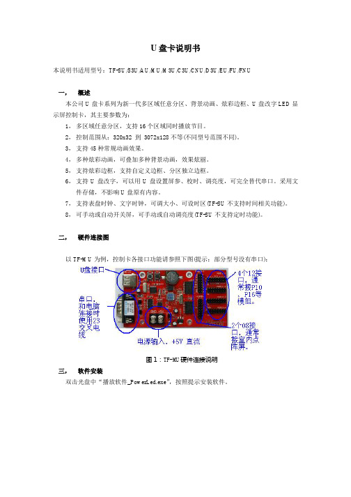
二,硬件连接图以TF-MU为例,控制卡各接口功能请参照下图(提示:部分型号没有串口):图1:TF-MU硬件连接说明三,软件安装双击光盘中“播放软件_PowerLed.exe”,按照提示安装软件。
图2: 安装程序的图标四,软件配置1 软件安装完后,请启动软件。
U盘卡可以脱机编辑内容,可以不连串口线,如果没有连接线,请不要单击“查屏”按钮。
2,基本参数设置,单击“工具”菜单,选择“屏参设置”,口令“168”。
(注意:如果屏参出厂时已经设好,请跳过此步骤。
)图3:屏参设置菜单3,在屏参设置界面中,设置好显示屏的“颜色类型”、“屏宽”、“屏高”和“扫描方式”、“数据极性”等参数。
图4:屏参设置界面如果未连串口线,单击“设置到控制卡”按钮时可能会提示“错误”,此时参数已保存到软件,请忽略此错误。
五,编辑节目工具栏上有“文本”、“表盘”等信息类型,按照需要添加,并修改内容,以及调整信息的位置和大小。
(软件安装好后,已经默认录入了一些信息,可以在其基础上修改)图6:软件编辑区域分布图六,导出节目到U盘通过“文件”->“导出到U盘”菜单,打开导出界面。
HL-UKey 客户端开发套件-win2000 邮件服务器(基于智能卡)配置手册

内部文档HL-UKey客户端开发套件-智能卡邮件加密配置手册目录(一)说明 (3)1.本地Windows帐户身份验证 (3)2.Active Directory集成的身份验证 (4)(二)配置域控制器,应用程序服务器,文件服务器及颁发和申请智能卡证书 (6)(三)配置邮件服务器 (6)(四)管理邮件服务器 (10)1.设置邮件存储位置 (10)2.管理域 (13)2.1 创建域 (13)2.2 管理域 (14)2.3 管理邮箱 (15)(五)配置客户端的收发邮件和数字签名 (18)5.1 Outlook Express设置 (18)5.2 数字签名 (21)5.3 加密执行 (22)(一)说明随着电子邮件和电子商务的逐渐普及,在Internet 上传递的机密信息也在迅速增加。
因此,对电子邮件的安全性和非公开性提出了更高的要求。
另外,随着ActiveX 控件、Script 脚本和Java 小程序的广泛使用,所收电子邮件中HTML 内容在未经许可的情况下访问或修改计算机中文件的可能性也在不断增强。
如何确保自己的个人邮件隐私不会被泄露,邮件在发送后没有被人截获、修改,许多安全专家都正在寻找行之有效的方法。
Windows Outlook Express 包含一些工具,有助于您防止欺骗行为、增强电子邮件的非公开性并防止对计算机进行未授权的访问。
这些工具通过安全区域使您能够更安全地发送和接收邮件并控制可能携带有害内容的电子邮件。
要使用Outlook Express 中的安全电子邮件,您需要数字ID (也叫数字证书)。
提供了一种在Internet 上验证您身份的方式,与您的身份证、司机驾照或日常生活中的其他身份证的方式相似。
数字ID 允许您给电子邮件签名,这样真正的收件人可确保该邮件确实是由您发来的并且没有受损。
另外,数字ID 允许其他人给您发送加密的邮件,邮件内容只有接收方本人才能解开。
要获得数字ID,您必须从发证机构获得,那是个负责发布数字证书的组织,并不断地验证数字证书是否持续有效。
U卡使用手册

一、打开软件,点击硬件配置,输入密码168,如图1所示。
图1 硬件配置登陆界面二、输入密码168,点击确定,进入硬件配置页面,选择单元板类型(P10单元板选择最后一个12接口4扫P10),以及屏高度和宽度,然后点击保存屏参。
如图2所示。
图2 硬件配置页面三、编辑内容。
在软件左边有一个节目管理的属性窗口,可以进行节目的添加和删除,分区的添加和删除。
在软件的下方的黑色窗体里面可以输入文字,选择字体和大小。
如图3所示。
图3 内容编辑界面四、保存到U盘。
编辑好节目内容后,把U盘插入电脑,然后点击菜单栏的保存到U盘,选择U盘所在的设备。
如需校时可把校时的勾打上,然后保存,保存成功然后关闭。
图4图4 保存到U盘五、保存内容到U盘成功后,把U盘从电脑上拔下,然后插到控制卡或者U盘延长线上,显示屏上会提示读取数据,当显示保存完毕后可把U盘拔掉。
屏就会正常走字。
注意事项:1、带U卡的电源至多可带8块P10单元板,不宜超出。
2、U盘应该选择普通的U盘,不可用SD卡之类的存储器。
3、控制卡与单元板之间的16P排线应注意方向,一般可排线的红边对着OE,控制卡上插排线的地方有个小三角形标志的一方为OE。
P10的单元板插在控制卡上的12接口上面。
常见问题:1、U盘插在控制卡上,显示屏上出现没有文件。
检查一下是否内容没有保存成功,把U盘再插入电脑,重新保存一遍内容。
2、显示屏显示不正常。
检查一下硬件配置,看单元板接口选择是否正确。
或者检查排线是否插对方向。
3、每次重启电源时显示屏显示花屏。
这种情况是由于控制卡供电不足,导致启动失败造成。
可以把带控制卡的电源少带两块单元板测试一下。
电子控制系统EHC35 IPS302控制器说明说明书

Electronic Control System EHC35IPS302 Control Unit Catalogue HY17-8359/UKDecember, 20012Parker HannifinMobile Controls Division Borås, SwedenRemote Controls - Electronic EHC35 - IPS302Catalogue HY17-8359/UKTechnical InformationApplicationsThe IPS302 is an electronic control unit designed for use with the ICL3, ICL4 and ICM4 lever units, and the PVE102, PVC102and PVC25 remote control valves.A single IPS unit can be used to control up to four double-acting functions. Easily accessible potentiometers on the front of the unit make it easy to set the start and final currents for the respective remote control valves.Construction and functionThe IPS302 control unit generates a pulse-width modulated square wave in order to minimize hysteresis in the controlled functions. The power amplifier board is current controlled by means of a current-sensing feedback, which makes the control unit independent of resistance changes in the solenoid or vari-ations in the supply voltage. Since the force of the solenoid is dependent only on the strength of the current through the coil,and on the number of turns in the coil, current control means that the IPS302 is independent of temperature variations in the solenoid coil of the remote control valve it controls. Evenresistances arising in cables and oxidizing contacts are com-pensated for by the IPS302. Quenching diodes for the solenoid coils are built into the IPS302.The control unit is equipped with stabilized DC output for connection to the ICL3, ICL4 and ICM4 lever units.A built-in safety circuit breaks the supply voltage if any of the outputs are activated incorrectly. The outputs are protected against transients, and the battery connection is protected against polarity errors and overvoltage.Each function is controlled by means of two potentio-meters. One controls the curve’s start point, and the other the slope of the curve. The final point is therefore determined by the curve’s start point and slope.The IPS302 is equipped with a filter, F1 or F2, for protection against external interference.Characteristics•Individual tuning of each function, even during operation,within a very wide range.•Simple construction and tuning of new systems.•Temperature compensated.•Protection against EMC.•CE marked.Ramp functionThe IPS302 can be equipped with a built-in ramp function,known as a down ramp. It is used to obtain a gentle retardation sequence. This provides effective protection against overload-ing of the machine in the event of careless operating move-ments. The operator is thus able to exploit the machine fully,but with minimal risk of damaging the machine or the goods being handled. Ramp times can be set between 0 and 2 sec-onds. The function is very useful in most applications, e.g. in cranes, forestry and agricultural machines, working platforms,mining and contractor’s plant.If the down ramp is set at, e.g. 1 second, and the lever is released from the actuated position to neutral, the control sig-nal will fall to 0 in 1 second (see curve in diagram). When con-trolling a directional valve, actuation of the spool is terminated once the control signal has fallen to the start signal level. The ramp function continues even if the lever is moved beyond the neutral position.The ramp time is set separately for each direction bymeans of easily accessible potentiometers on the front of the unit.TuningEach function is regulated by means of three potentiometers:“Min” regulates the start point of the curve.“Max” regulates the slope of the curve.“Ramp” regulates the down-ramp time.See also the installation and servicing instructions, printed mat-ter No. 9129 8332-02.Technical dataVersion12V24VAmbient temperature range for function -30 ºC to +50 ºC -30 ºC to +50 ºC Approved test CE marked CE marked Supply voltage9.5 – 16 V DC 20 – 32 V DC Supply voltage ripple, max.10%10%Overvoltage protection 18 V DC 33 V DC Current consumption, idling 160 mA 115 mA Load per channel, max. 1.5 A 1 AStart current50 – 800 mA*50 – 400 mA*Diff. between start and final current 0 – 1300 mA*0 – 850 mA**Frequency 50 – 150 Hz 50 – 150 Hz External fusing8 A 6.3 A Supply voltage to lever unit 5 V 8 V Protection rating IP20IP20(recommended for installation in cab)Weightwith 3 amplifier boardsapprox. 1.3 kg approx. 1.3 kgSettings on delivery:Start current 375 mA 200 mA Final current 725 mA 400 mA Frequency100 Hz100 Hz* On connection of 8.9 ohm load, PVE102-12. 50 ºC ** On connection of 27 ohm load, PVE102-24. 50 ºCRamp function, IPS302.Subject to alteration without prior notice. The diagrams in the catalog show typical curves only. While the contents of the catalog are updated continuously, the validity of the information given should always be confirmed. Technical information in the catalog is applicable at an oil viscosity of 30 mm 2/s and temperature of 50 ºC. For more detailed infor-mation, please contact Parker.3Parker HannifinMobile Controls Division Borås, SwedenRemote Controls - Electronic EHC35 - IPS302Catalogue HY17-8359/UKTechnical InformationDiagramDimensionsVoltagePilot valvesLever unitChannelChannelPin No.Contact AContact AIPS302Contact A:Pin Nos. 2 and 8 (earth) and 10 not connected.Pin Nos. 1 and 7 for supply voltage.F1F2For further information please contact:Parker Hannifin Mobile Controls Division SE-501 78 Borås SwedenTel. +46 33 700 52 00 Fax +46 33 12 11 43 Catalogue HY17-8359/UK Ed. 0150。
杭州美控 U-MIK-PH8.0-MYCN2 pH ORP控制器使用说明书

杭州美控自动化技术有限公司更多资讯请扫二维码服务电话:400-152-1718杭州美控自动化技术有限公司 U-MIK-PH8.0-M Y CN2第2版pH/ORP控制器使用说明书前言●感谢您购买本公司产品。
●本手册是关于产品的各项功能、接线方法、设置方法、操作方法、故障处理方法等的说明书。
●在操作之前请仔细阅读本手册,正确使用本产品,避免由于错误操作造成不必要的损失。
●在您阅读完后,请妥善保管在便于随时取阅的地方,以便操作时参照。
注意●本手册内容如因功能升级等有修改时,恕不通知。
●本手册内容我们力求正确无误,如果您发现有误,请与我们联系。
●本手册内容严禁转载、复制。
●本产品禁止使用在防爆场合。
版本U-MIK-PH8.0-MYCN2第二版2021年4月安全注意事项为了安全使用本产品,操作时请务必遵守以下描述的安全注意事项。
关于本手册●请将本手册交于操作者阅读。
●在操作之前,请熟读本手册,并对产品有深入了解。
●本手册只对产品的功能进行阐述,本公司不保证该产品将适合于用户的某一特殊用途。
产品保护、安全及改造相关注意事项●为了确保安全使用本产品以及由其控制的系统,操作时请务必遵守本手册中所述说明和注意事项。
如果违反操作规程,则有可能会损坏本产品所提供的保护功能。
对由以上情况产生的质量、性能、功能和安全问题,本公司不承担任何责任。
●为本产品及其控制系统安装防雷装置,或设计安装单独的安全保护电路时,需要借助其他的设备来实现。
●如果需要更换产品的零部件,请使用本公司指定的型号规格。
●本产品不适用于直接关系到人身安全的系统。
如核动力设备、使用放射能的设备、铁路系统、航空机器、船舶设备、航空设备和医疗器械等。
如有应用,用户有责任使用额外的设备或系统确保人身安全。
●请勿改造本产品。
在本手册中使用了以下几种安全标志:危险标志,若不采取适当的预防措施,将导致严重的人身伤害、仪表损坏或重大财产损失等事故。
警示标志,提醒您对产品有关的重要信息特别注意。
USBCAN-I II+工业级高性能 CAN 接口卡产品用户手册说明书

USBCAN-I/II+用户手册工业级高性能CAN 接口卡UserManual UM01010101 V1.04 Date: 2020/03/31类别内容关键词USBCAN卡,高性能CAN接口卡摘要USBCAN-I/II+产品性能描述与使用指导修订历史目录1. 功能简介 (1)1.1产品概述 (1)1.2功能特点 (1)1.3典型应用 (2)2. 设备安装 (3)2.1供电模式 (3)2.1.1外部电源供电模式 (3)2.1.2USB总线供电模式 (3)2.2CAN-bus连接器 (3)2.3信号指示灯 (4)2.3.1USBCAN-I+信号指示灯 (4)2.3.2USBCAN-II+信号指示灯 (5)2.4系统连接 (5)2.4.1CAN总线连接 (5)2.4.2总线终端电阻 (6)2.4.3USB总线连接 (6)3. 驱动程序 (7)3.1驱动安装 (7)3.2卸载设备驱动 (10)4. 设备三维尺寸图 (12)5. 常见问题 (13)6. 检查和维护 (16)7. 附录:CAN2.0B协议帧格式 (17)8. 免责声明 (19)1. 功能简介1.1 产品概述USBCAN-I/II+高性能CAN接口卡是与USB2.0总线全速规范兼容的,集成1~2路CAN 接口的高性能型CAN-bus总线通讯接口卡。
采用USBCAN-I/II+高性能CAN接口卡,PC可以通过USB总线连接至CAN-bus网络,构成现场总线实验室、工业控制、高性能小区、汽车电子网络等CAN-bus网络领域中数据处理、数据采集的CAN-bus网络控制节点。
USBCAN-I/II+高性能CAN接口卡是CAN-bus产品开发、CAN-bus数据分析的强大工具;同时,具有体积小巧、即插即用等特点,也是便携式系统用户的最佳选择。
USBCAN-I/II+接口卡上自带电气隔离模块,使接口卡避免由于地环流的损坏,增强系统在恶劣环境中使用的可靠性。
U盘控制卡使用说明
U盘LED控制卡使用说明注意:控制卡串口跟电脑串口连线均为235交叉,即2接3, 3接2,5接5。
可直接用U盘传输屏参。
P10半户外单元板:单色8位下折三次室内3.0 3.75 5.0单元板单色/双色无打折。
行译码一般都是138译码。
注意单双色的选取。
一、节目制作1、点击图1标注1处的“新建按钮”。
然后在图1所示2处设置您屏体的屏宽点数和屏高点数。
设置好后点“确定”按钮。
图12、屏参设置(以P10单红为例)单击图2标注3处“设置”按钮(设置密码为:888);然后选中图2标注4处“OE反向”(若勾选后屏幕亮度很低,则不需勾);然后设置屏体亮度(参数为1-990,数值越大,亮度越高);设置好后,点“保存”按钮。
图2二、编辑内容如图5所示图5点击图5所示标注的1处的“通用”按钮。
图5标注2处浅蓝色框可以拉动。
(浅蓝色框即内容显示区域)。
在“文本编辑”区域内输入自己所需的内容。
然后在“字幕特效”选项卡内选择所需动画效果。
1、编辑好节目后,点击图标中的U盘按钮,弹出保存对话框:如下图所示,可自己选取保存位置,默认保存文件名为program,请勿更改此文件名。
图22、将U盘格式化,文件系统选择FAT图3此做法是由于目前市场上有不少U盘存储范围是虚假的,存在扩容现象。
(一般可跳过此步骤)格式化完成后,将刚才保存的U盘文件program.dat移动至U盘当中,注意,在用U盘传送完节目之前,不要再U盘中存放其他文件。
3、在控制断电时插上U盘,然后再开电,等待控制卡读取U 盘内容,大概5到6秒后就能读取完成,读取完成后,显示屏上会显示所读取的内容。
若要拔掉U盘,最好在控制卡没电时再拔。
控制卡正确读取现象插上U盘后,给控制卡开电,前两到三秒钟,屏上会有亮框,然后如果屏全灭,说明正在读取U盘里面的节目,等待屏上显示更新后的内容。
如果亮框消失后,屏上立即显示以前的内容,请对照上面操作步骤,看是否有错误的地方。
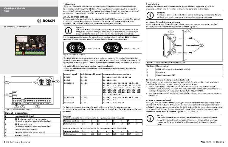
霍尼韦尔 伏卡安全系统 B208 八路输入模块操作指南说明书
Callout Description1Heartbeat LED (blue)2SDI2 interconnect wiring connectors(to control panel or additional modules) 3SDI2 terminal strip(to control panel or additional modules) 4Tamper switch connector5Terminal connector (point inputs)6Address switches 1 OverviewThe B208 Octo-input Module is an 8 point supervised expansion device that connectsto control panels through the SDI2 bus. This module communicates back to the controlpanel all point status changes. The inputs are accessed through on-board screw terminalconnections. The on-board switches are used to specify module addresses.2 SDI2 address settingsTwo address switches determine the address for the B208 Octo-input Module. The controlpanel uses the address for communications. The address also determines the pointnumbers. Use a slotted screwdriver to set the two address switches.2.1 Valid addresses and point numbers per control panelValid B208 addresses are dependent on the number of points allowed by a particularcontrol panel.3 InstallationAfter you set the address switches for the proper address, install the B208 in theenclosure and then wire the module to the control panel and to the inputs.Control panel Valid B208 addresses Corresponding point numbersB551201 - 0411 - 18, 21 - 28, 31 - 38, 41 - 48B451201 - 0211 - 18, 21 - 28D9412GV401 - 2411 - 18, 21 - 28, 31 - 38, 41 - 48, 51 - 58,61 - 68, 71 - 78, 81 - 88, 91 - 98, 101 - 108,111 - 118, 121 - 127, 131 - 138, 141 - 148,151 - 158, 161 - 168, 171 - 178, 181 - 188,191 - 198, 201 - 208, 211 - 218, 221 - 228,231 - 238, 241 - 247D7412GV401 - 0711 - 18, 21 - 28, 31 - 38, 41 - 48, 51 - 58,61 - 68, 71 - 75D7212GV401 - 0311 - 18, 21 - 28, 31 - 38Figure 2.1: Address switchesTo determine the point numbers for each address, multiply the address numberby 10 for the base number, and then use numbers 1 through 8 in the ones place for the pointnumbers.ExamplesFor B208 address 01the point numbers for the input devices are 11 through 18:Terminal numbers12345678Point numbers1112131415161718For B208 address 11 the point numbers for the input devices are 111 through 118:Terminal numbers12345678Point numbers111112113114115116117118= Inputs 11 to 18= Inputs 111 to 118Set the address switches per the control panel confi guration. If multiple B208 modulesreside on the same system, each B208 module must have a unique address.NOTICE!The module reads the address switch setting only during power up. If youchange the switches after you apply power to the module, you must cyclethe power to the module in order for the new setting to be enabled.The B208 address switches provide a tens and ones value for the module’s address. Forsingle-digit address numbers 1 through 9, set the tens switch to 0 and the ones digit to theappropriate number. Figure 2.1 shows the address switches setting for addresses 9 and 11.3.1 Mount the module in the enclosureMount the B208 into the enclosure’s 3-hole mounting pattern using the suppliedmounting screws and mounting bracket. Refer to Figure 3.1.3.2 Mount and wire the tamper switch (optional)You can connect an enclosure door tamper switch for one module in an enclosure.Installing the optional tamper switch for use with a B208:1. Mount the ICP-EZTS Tamper Switch (P/N: F01U009269) into the enclosure’stamper switch mounting location. For complete instructions, refer to EZTS Coverand Wall Tamper Switch Installation Guide (P/N: F01U003734).2. Plug the tamper switch wire onto the module’s tamper switch connector. Refer toFigure 1.1.3.3 Wire to the control panelWhen you wire a B208 to a control panel, you can use either the module’s terminal striplabeled with PWR, A, B, and COM, or the module’s interconnect wiring connectors (wireincluded). Interconnect wiring parallels the PWR, A, B, and COM terminals on the terminalstrip. Figure 1.1 indicates the location of both the terminal strip and the interconnectconnectors on the module. Refer to Figures 3.2, 3.3, and 3.4.NOTICE!Use either the terminal strip wiring or interconnect wiring connector tothe control panel. Do not use both. When connecting multiple modules,you can combine terminal strip and interconnect wiring connectors inseries.Callout Description1B208 with mounting bracket installed2Enclosure3Mounting screws (3)Figure 1.1: B208 Octo-input Module NOTICE!Remove all power (AC and Battery) before making any connections. Failure to do so may result in personal injury and/or equipment damage.Callout Description1B208 Octo-input Module 2B208 sensor loops31 k Ω EOL resistor (ICP-1K22AWG-10)4Wiring to additional sensor loops3.4 Sensor Loop WiringWire resistance on each sensor loop must be less than 100 Ω with the detection devices connected. The terminal strip supports 12 to 22 AWG (0.65 to 2 mm) wires.The B208 detects open, short, normal, and ground fault circuit conditions on its sensor loops and transmits the conditions to the control panel. Each sensor loop is assigned a point number and transmits to the control panel individually. Run wires away from the premises telephone and AC wiring. Refer to Figure 3.5.4 LED descriptionsThe B208 Octo-input Module includes one blue heartbeat LED to indicate that the module has power and to indicate the module’s current state. Refer(GV4 Series control panel shown)Callout Description1Bosch control panel 2B208 Octo-input ModulesCallout Description1Bosch control panel 2B208 Octo-input Modules(GV4 Series control panel shown)(GV4 Series control panel shown)Callout Description1Terminal strip wiring (SDI2)2Interconnect cable (P/N: F01U079745) (included)Dimensions 2.5 in x 3.8 in x 0.60 in (63.75 mm x 96 mm x 15.25 mm)Voltage (operating)12 V nominal Current (maximum)35 mAOperating temperature +32°F to +122°F (0°C to +50°C)Relative humidity 5% to 93% at +90°F (+32°C) non-condensingLoop inputsUp to eight inputs. Input contacts may be Normally Open (NO) orNormally Closed (NC) with 1k Ω EOL resistor(s) for supervision. NOTICE: Normally Closed (NC) is not permitted in Fire installations.Loop End-of-Line (EOL) resistance1k ΩLoop wiring resistance 100 Ω maximum Loop statesShort: 0 - 1.1 VDCNormal: 1.25 - 1.9 VDC Open: 2.25 - 5 VDCTerminal wire size 12 AWG to 22 AWG (2 mm to 0.65 mm)SDI2 wiringMaximum distance - Wire size (Unshielded wire only): 1000 ft (305 m) - 22 AWG (0.65 mm)1000 ft (305 m) - 18 AWG (2 mm)CompatibilityB5512 (Up to 4 modules)B4512 (Up to 2 modules)D9412GV4 (Up to 24 modules)D7412GV4 (Up to 7 modules)D7212GV4 (Up to 3 modules)7 Speci fi cationsCopyrightThis document is the intellectual property of Bosch Security Systems, Inc. and is protected by copyright. All rights reserved.TrademarksAll hardware and software product names used in this document are likely to be registered trademarks and must be treated accordingly.Determine Bosch Security Systems, Inc. product manufacturing datesUse the serial number located on the product label and refer to the Bosch Security Systems, Inc. web site at /datecodes/.RegionUSUL 365 - Police Station Connected Burglar Alarm Units and Systems UL 609 - Local Burglar Alarm Units and Systems UL 985 - Household Fire Warning System Units UL 1076 - Proprietary Burglar Alarm Units and Systems UL 1023 - Household Burglar-Alarm System Units UL 1610 - Central-Station Burglar-Alarm UnitsUL 864 - Control Units and Accessories for Fire Alarm Systems CSFM - California Of fi ce of The State Fire Marshal FCC Part 15 Class B FM Approval 3010CanadaCAN/ULC-S304 Central and Monitoring Station Burglar Alarm Units ULC/ORD-C1023 Household Burglar Alarm System Units CAN/ULC-S303 Local Burglar Alarm Units and Systems ULC/ORD-C1076 Proprietary Burglar Alarm Units and Systems6 Certi fi cationsFlashing patterns do not start until the tamper is open (short is removed). The following is an example: The version 1.4.3 would be shown as LED fl ashes:[3 second pause] *___****___*** [3 second pause, then normal operation].When the tamper switch is activated (closed to open), the heartbeat LED stays OFF for 3 sec before indicating the fi rmware version. The LED pulses the major, minor, and micro digits of the fi rmware version, with a 1 sec pause after each digit.5 Show the fi rmware versionTo show the fi rmware version using an LED fl ash pattern: - If the optional tamper switch is installed:With the enclosure door open, activate the tamper switch (push and release the switch).- If the optional tamper switch is NOT installed: Momentarily short the tamper pins.。
- 1、下载文档前请自行甄别文档内容的完整性,平台不提供额外的编辑、内容补充、找答案等附加服务。
- 2、"仅部分预览"的文档,不可在线预览部分如存在完整性等问题,可反馈申请退款(可完整预览的文档不适用该条件!)。
- 3、如文档侵犯您的权益,请联系客服反馈,我们会尽快为您处理(人工客服工作时间:9:00-18:30)。
c.选中节目页新建窗口,设置窗口属性(窗口大小、名称、位置、边框、背景等),输入窗口内容并设置内容格式。
d.保存节目
e.发送节目
图2.2-1
图2.2-2
图2.2-3
2.2.1
连接好串口后选择快捷图标中的发送至当前显示屏或者选择屏幕后在属性区域里选择发送节目,如果2.2-4所示:
固件升级:用户自行升级控制卡硬件程序。
5帮助
使用说明(U):在这里可以获取使用说明信息。
硬件手册:在这里可以获取LED控制卡硬件说明信息。
更新记录:在这里可以获取更新记录信息。
技术支持:获取技术支持服务联系方式,在有需要的时候可以获得技术支持。
关于软件:在此可以获取本软件的版权和版本信息。
2.
2.1
关闭屏幕:“关闭屏幕”用于关闭选中的LED屏幕。执行该操作后该显示屏停止播放所存储的节目,不显示。
亮度调节:亮度调节,分为手动自动两种调节方式。
定时开关:定时自动开关屏幕,可以根据需要节省用电。
群发屏幕:“群发屏幕”用于多个显示屏时的节目数据发送,执行该操作后所有打开的节目都被发送到对应的屏幕上。
全部校准:“全部校准”用于调整全部屏幕的时间与电脑同步。
e.保存配置参数:保存参数数据到本机。
图2.1-2
2.1.1
如果有连接串口线,在设置好屏幕参数后选择“发送后保存”则可以将参数发送到控制卡中以更改控制卡里的参数设置,操作过程和结果可在提示栏里显示。
2.1.2
如果需要使用U盘来更改参数,插入U盘,在设置完参数后选择导出当前配置,在弹出框中选择可移动磁盘如:图2.1-3,或者在保存配置后在主界面中选中屏幕后在设置菜单栏下的硬件参数中“导出到可移动磁盘”,如:图2.1-4。更改后的参数需要在本地保存则点击“保存配置”。
图2.2-7
常见问题及解决办法
1、使用LED图文屏控制软件获取参数时提示栏提示“获取失败”请检查屏幕是否连接,配置好参数后发送至控制卡提示发送失败。
原因:
a.硬件:
1)控制卡是否已正确接通5V直流电源;
2)本卡用RS-232方式通讯,串口线使用2-2 3-3 5-5直通线;
3)串口线两端端口是否有松动或脱落现象;
选择设置菜单栏下的硬件参数进入参数设置,密码为168:
图2.1-1
设置硬件参数、通讯参数、模组参数等,如图2.1-2
参数操作说明:
a.导出当前配置:导出参数到可移动磁盘;
b.恢复配置参数:恢复之前备份的参数数据;
c.备份配置参数:配置当前设置的参数数据;
d.发送后保存:发送参数到控制卡后并保存到本机;
图2.2-4
2.2.2
插入U盘后选择文件菜单栏下的“导出到”然后选择“媒体文件”,在弹出的界面中选择U盘所在的路径,更改节目名称并保存。如:图2.2-5,或者直接选择导出到可移动磁盘,图2.2-6
2.2-5
图2.2-6
2.2.3
连接好U卡后选择文件菜单下的“导出到”选择“U卡(E)”,节目发送成功后将U卡拔出插到控制卡上稍等一会即可将节目转发到控制卡中。如图2.2-7
设置:用于设置控制器的运行参数和软件参数的设置,如:LED屏的数量、尺寸、通讯模式、软件语言的选择、画面捕捉器参数设置等。
维护:提供屏幕测试、固件升级功能。
帮助:技术支持,软件版本号以及帮助手册
1.文件:
新建文件:“新建文件”用于创建新的节目文件。
打开文件:“打开文件”是用于打开一个已经存在的播放文件(后缀名为hled)。
2)U盘的属性中的文件系统是否为FAT格式,如果不是需格式化为FAT格式。
b.软件:
1)节目制作时屏幕的参数设置是否与控制卡内参数一致;
2)U盘内包含其它屏幕的参数文件。
4)电脑串口通讯是否有损坏;
5)如果使用USB转串口,请检查驱动是否正确安装,虚拟串口号是否在1-8之间,电脑是否已识别到;
6)通讯线超长(大于50米),线材质量过差,环境电磁干扰过大。
b.软件:
1)串口号选择是否设置正确;
2)波特率是否设置合适(线路较长时,波特率建议设置为9600);
3)用于通讯的串口是否被其他程序占用(可能打开多个控制系统);
获取参数:“获取参数”用于获取硬件参数设置值。
传输模式:“传输模式”包含快速传输和正常传输两种传输模式。
捕捉参数:“捕捉参数”用于设置图文窗口中画面捕捉器的参数。
环境配置:配置默认节目格式、默认字体、默认特效、界面风格
语言设定:“语言设定”用于选择操作界面的语言类型。
4维护
屏幕测试:通过显示方式的选择来测试屏幕,使用‘上一个’、‘下一个’来顺序测试屏幕显示方式,测试完成后返回即可。屏幕测试时用户可以看到控制卡的固件版本。
全部开启:“全部开启”用于开启所有的LED屏幕。执行该操作后所有显示屏播放所存储的节目。
全部关闭:“全部关闭”用于关闭选中的LED屏幕。执行该操作后所有显示屏停止播放所存储的节目,不显示。
3.设置
硬件参数:“硬件参数”用于设置屏幕、控制卡和软件上的各种参数,包括:屏幕数量、尺寸、控制器类型、传输模式、信号类型等。
图2.1-3
图2.1-4
2
节目分为三级结构:屏幕—节目—窗口,屏幕下可建多个节目页,并且每个节目页下可以建多个窗口(文本文件窗、单行文本窗、日期时间窗、计时显示窗等)。
点击各个结构在右侧可看到对应的属性,如图2.2-1,2.2-2,2.2-3。
操作步骤:
a.连接好屏幕后应先进去参数设置设置好屏幕的参数;
保存文件:“保存文件”可用来保存当前编辑的节目。
另存为:“另存为”与“保存”之间的唯一区别在于:每次当您单击“另存为”的时候,系统都会弹出一个“另存为”的对话框,您可以指定新路径和文件名以保存当前节目数据。
导出到:将节目内容导出到U卡或者为多媒体文件
退出系统“退出系统”用于退出整个应用程序。
2.控制
HL302U
1.
主菜单主要包含五个子菜单,分别是:文件(F)、控制(C)、设置(S)、维护(M)和帮助(H)。菜单名后括号内的字母为各个菜单项的快捷方式。如:“文件”菜单项可通过按键盘上的“ALT+F”的组合键来打开。
文件:用于节目文件的建立、保存、另存,及退出应用程序的操作。
控制:主要用于预览节目以及控制显示屏。
发布消息:点击进入消息模式,可以发布即时消息、体育比分。
预览:“预览”用于预览目前的节目文件。
停止:“停止”用于停止预览当前播放的节目。
发送节目:“发送节目”用于发送所选的节目至当前的LED屏幕上。
校正时间:“校正时间”用于调整当前屏幕的时间与电脑同步。
开启屏幕:“开启当屏幕”用于开启选中的LED屏幕。执行该操作后该显示屏播放所存储的节目。
3)屏幕是否处于关机状态,可点击“开启显示屏”强制开启;
4)节目是否设置为定时播放,播放时段是否设置正确,屏幕时间是否准确,可同步时间;
3、使用U盘更改节目时,节目存储到U盘后连接至控制卡后屏幕不显示或者显示异常。
原因:
a.硬件:
1)请确认U盘与控制卡连接良好,如有使用USB延长线,则长度不宜超过2m,且检测通讯线是否正常;
4)通讯协议是否正确选择,专用协议还是通用协议。
2、使用LED图文屏控制平台发送数据成功,但显示屏无任何显示或者显示屏显示乱码或错字;
原因:
a.硬件:
1)显示屏是否已正确接通5V直流电源;
2)排线两端是否连接正确;
3)确认扁平线是否损坏,可进入“屏幕测试”检查。
b.软件
1)显示屏参号是否选择正确;