远距离读写器 20M RFID UHF读卡器 JT-8290A 产品说明书
一体化远距离读卡器说明书
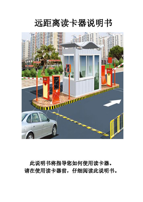
远距离读卡器说明书此说明书将指导您如何使用读卡器。
请在使用读卡器前,仔细阅读此说明书。
一、产品概述随着社会现代化进程的不断推进,人们不断追求高品质生活,汽车已逐步成为人们出行的交通工具。
车辆的迅猛发展给传统的手动刷卡停车场管理系统也带了巨大压力。
上、下班高峰期排队等候刷卡、上坡车道停车刷卡、雨雪天气伸手刷卡等有诸多不便。
科技的发展,先进技术的应用,也更好的解决了传统产品的不足。
远距离不停车自动感应产品的诞生,以便捷、减排、省时、节油等传统产品无法比拟的优势,将全面取代传统式手工刷卡的停车场系统。
因停车场系统应用的特殊性,并不是任何一款远距离读卡设备都能发挥应有的功能,在实际应用中信号能否穿透汽车隔热膜、相临车道信号干扰、跟车信号干扰、微波辐射危害、信号衰减、电磁兼容等关键技术成为产品稳定性的重要因素。
我公司生产的定向远距离读卡器利用红外和微波同步通讯技术,充分考虑产品在停车场系统和ETC系统应用的特点,是国内目前唯一能解决准确定位和互相干扰的远距离读卡设备。
二、产品性能三、系统原理该款远距离定向读卡器结合了红外与射频通讯特点,互补两个不同频率通道的工作优势,相互进行信息传递。
射频是一个无方向的电磁波,难以准确定向,但通讯速度快;而红外具有严格的角度定位,但通讯速度慢;在停车场实际应用中选用某一个通道通讯难以达到理想的使用要求。
原理:读卡器发射60度红外扫描信号,红外信号是经过加密的数据,包含了唤醒编码、机器编码信息;当休眠中的远距离卡进入读卡器发送的红外信号范围时,立即被唤醒工作,发射射频电磁波发送远距离卡内码,在发送卡内码的同时也将读卡器机器码附带传递给读卡器;读卡器接收到卡号后对首先对机器码验证,与该机身码相符的为有效卡直接上传给上位机,与该机器码不符的直接删除,避免了临近车道和跟车的串号干扰。
四 、产品特点⑪穿透性:可穿透任何金属汽车防爆膜,远距离卡放置到车内,无需摇窗户可自动识别感应; ⑫方向性:采用红外定位射频传输双通道模式方式工作,具有严格的方向性和稳定性,读卡区60度以外绝不读卡。
技术解决方案英国有限公司(TSL)RFID移动读取器说明书
T echnology Solutions UK Ltd (TSL ®), part of HID Global, is a leading manufacturer of high performance mobile RFID readers used to identify and track products, assets, data or personnel.For over two decades, TSL ® has delivered innovative data capture solutions to Fortune 500 companies around the world using a global network of distributors and system integrators. Specialist in-house teams design all aspects of the finished products and software ecosystems, including electronics, firmware, application development tools, RF design and injection mould tooling.TSL ® is an ISO 9001:2015 certified company.Copyright © 2018 Technology Solutions (UK) Ltd. All rights reserved.No part of this publication may be reproduced or used in any form, or by any electrical or mechanical means, without permission in writing from T echnology Solutions (UK) Ltd. This includes electronic or mechanical means, such as photocopying, recording, or information storage and retrieval systems. The material in this manual is subject to change without notice.T echnology Solutions (UK) Ltd (TSL ®) reserves the right to make changes to any software or product to improve reliability, function, or design. TSL ® does not assume any product liability arising out of, or in connection with, the application or use of any product, circuit, or application described herein. No license is granted, either expressly or by implication, estoppel, or otherwise under any patent right or patent, covering or relating to any combination, system, apparatus, machine, material, method, or process in which TSL ® products might be used. An implied license exists only for equipment, circuits, and subsystems contained in TSL ® products. TSL ® and the TSL ® logo are registered trademarks of TSL ®. Other product names mentioned in this manual may be trademarks or registered trademarks of their respective companies and are hereby acknowledged.All software is provided strictly on an “as is” basis. All software, including firmware, furnished to the user is on a licensed basis. TSL ® grants to the user a non-transferable and non-exclusive license to use each software or firmware program delivered hereunder (licensed program). Except as noted below, such license may not be assigned, sublicensed, or otherwise transferred by the user without prior written consent of TSL ®. No right to copy a licensed program in whole or in part is granted, except as permitted under copyright law. The user shall not modify, merge, or incorporate any form or portion of a licensed program with other program material, create a derivative work from a licensed program, or use a licensed program in a network without written permission from TSL ®. The user agrees to maintain TSL ®’s copyright notice on the licensed programs delivered hereunder, and to include the same on any authorized copies it makes, in whole or in part. The user agrees not to decompile, disassemble, decode, or reverse engineer any licensed program delivered to the user or any portion thereof.The Bluetooth ® word mark and logos are registered trademarks owned by Bluetooth SIG, Inc. and any use of such marks by T echnology Solutions (UK) Ltd is under license. Other trademarks and trade names are those of their respective owners.TERMS & CONDITIONSDesign • Development • ManufactureTECHNOLOGY SOLUTIONSUKLTDHEALTH AND SAFETYPower SupplyLaser WarningA warning label is present on the back of the antenna when a barcode reader antenna is fitted.The barcode reader module complies with 21 CFR 1040.10 and 1040.11 except for deviations pursuant to Laser Notice No. 50, dated June 24, 2007, EN60825-1:2007 and IEC60825-1:2001 (Ed.1.2)Avoid unnecessary exposure to the laser light emitted from the barcode reader.Caution: Use of controls, adjustments or performance of procedures other than those specified herein may result in hazardous laser light exposure.Caution: Viewing the illumination from the barcode reader with optical instruments may result in increased hazard.ISO 9001: 2015Address:Technology Solutions (UK) LimitedSuite A, Loughborough T echnology Centre, Epinal Way,Loughborough, Leicestershire, LE11 3GE. United Kingdom.Telephone:+44 (0)1509 238248Fax:+44 (0)1509 214144Email:*****************Website:CONTACTTSL ® - Global Leaders in Mobile RFIDABOUTSUPPORTT o download the 2128 Bluetooth ® UHF RFID Reader User Guide, visit: /2128-downloadsUser DocumentationIf you are having difficulties using your 2128 UHF Reader, please use the online Troubleshooting Guide at: /troubleshooting-guidesIf you have consulted both the 2128 UHF Reader User Guide and the online Troubleshooting Guide and still need assistance, contact TSL ® at: /contactTroubleshootingWarrantyTSL ®’s hardware Products are warranted against manufacturing defects for a period of twelve (12) months from the date of shipment, unless otherwise provided by TSL ® in writing, provided the Product remains unmodified and is operated under normal and proper conditions.For further warranty information and provisions, please see the Warranty section of the 2128 UHF Reader User Guide (available to download at /2128-downloads )Use only TSL ®-approved cradles and power supplies with the 2128 UHF Reader. Use of an alternative power supply will invalidate any approval given to this device, void the warranty for the product and may be dangerous.User Guide and DownloadsQuick Start GuideStatusThe Reader is awake but there is no connection The Reader is awake and connected to a hostThe Reader has successfully read a tag or barcode or executed the alert commandAntenna error - try reseating the antennaBattery low warning (<10% capacity remaining), please recharge immediatelyBattery charging with battery level less than 33%Battery charging with battery level less than or equal to 66%Battery charging with battery level greater than 66%There is a charge error / battery fault The Reader is fully charged The Reader is off and not chargingCaution: In order to avoid or minimize the potential risk of ergonomic injury, follow the recommendations below. Consult with your local Health & Safety Manager to ensure that you are adhering to your company’s safety programs to prevent employee injury.●Reduce or eliminate repetitive motion ●Maintain a natural position●Reduce or eliminate excessive force●Keep frequently used objects within easy reach ●Perform tasks at correct heights ●Reduce or eliminate vibrationErgonomic Recommendations●Reduce or eliminate direct pressure ●Provide adjustable workstations ●Provide adequate clearance●Provide a suitable working environment ●Improve work proceduresBluetooth ® UHF RFID Readerlist of Bluetooth® devices, the 2128 UHF Reader will be identified by its serial number (xxxxxx-2128). (Make sure the Reader has not ‘timed-out’ and gone to sleep, as it will not be discoverable).Once a Bluetooth® connection has been successfully established, the blue LED will stop flashing and stay on continuously.Install a compatible application (such as TSL®’s RFID ExplorerApp) on your smartphone or tablet. RFID Explorer can bedownloaded from the App Store or Google Play.Open your compatible application and select the 2128 UHF Readerfrom the list of available devices. The 2128 UHF Reader should now be ready to use! INTRODUCTIONFIGURE 1:Parts of the2128 UHF RFID ReaderThe TSL® 2128 Bluetooth® UHF RFID Reader provides Ultra High Frequency (UHF) Radio FrequencyIdentification (RFID), with optional barcode scanning functionality. The unit can be used in batch modeusing an optional Micro SD card, or can be connected via USB through the ePop-Loq® socket, orconnected to a host device via Bluetooth®. The 2128 can read and write to EPC Global Class 1 Gen 2UHF RFID transponders.For detailed information on setting up and using the 2128 UHF Reader, please visit/2128-downloads to download the 2128 UHF Reader User Guide.Antenna Release LatchDocking ConnectorStatus LEDsTrigger ButtonUHF AntennaePop-Loq® SocketTrigger HandleBATTERY INSTALLATIONThe battery is charged using a docking station and is therefore unlikely to need to be changed onceinstalled. T o access the battery compartment the grip handle must first be removed.Push the Handle Release latchupwards and slide the TriggerHandle off the Main BodyRemove the Battery CoverInsert the Battery,ensuring that thebattery contacts alignwith the contacts onthe Main Body.Re-attach the BatteryCover and TriggerHandle.BLUETOOTH® OPERATING MODESFor a detailed comparison between Bluetooth® HID and SPP modes - and instructions on how toswitch between these modes - download the ‘Comparison of Bluetooth® Modes for TSL® UHF Readers’document from the 2128 Downloads Page (/2128-downloads).For information and examples on configuring HID mode, download the ‘Bluetooth® HID mode’application note (/2128-downloads).To pair with a Bluetooth® host deviceREADING TRANSPONDERSThe 2128 UHF Reader can read and write to UHF RFIDtransponders when they are in range of the antenna. Theantenna is located on the front of the 2128 UHF Readerand the read zone is in front of the antenna.The range at which a transponder can be read dependson the transponder type and size, and the number oftransponders in the field.BUTTON OPERATIONThe 2128 UHF Reader has a Primary button action and aSecondary button action, which can be initiated by singleor double-clicks of the T rigger Button:Single-click and hold:Primary action (by default, the Primary action scans forUHF transponders).Double-click and hold:Secondary action (by default, the Secondary actioninitiates the laser barcode scanner - this is only availablewhen using the 2D Imager Antenna variant).The Single and Double-click button options are alsoprogrammable for custom applications.FIGURE 4: Antenna read directionCHARGINGTo comply with internationalshipping regulations,all batteriesincluded with TSL ® products aredischarged to less than 30% oftheir maximum capacity whenshipped. It is therefore importantthat the unit is fully charged beforeusing your 2128 UHF Reader forthe first time.The 2128 UHF Reader can becharged using the dedicated 2128Docking Station. The DockingStation has an input for power anda Mini USB connector for datacommunications.FIGURE 2: Charging the 2128 UHF ReaderUse 5.2V 4A PowerSupply OnlyMain BodyATTACHING DEVICESThe 2128 UHF RFID Reader has an ePop-Loq® mount which allows smartphones and mobile terminalsto be physically attached to the 2128 UHF Reader. Custom ePop-Loq® cases allow compatible deviceswith custom applications to communicate with the reader via USB instead of Bluetooth®.ePop-Loq® studePop-Loq® socketePop-Loq® caseFIGURE 5: ePop-Loq® component partsPLEASE NOTE: Our UHF RFID Bluetooth® Readers support two different modes of operation overBluetooth®.1. Bluetooth® SPP ModeBy default the 2128 UHF Reader is set to SPP Mode. In this mode, the 2128 UHF Reader will only workwith Apps that have been written with specific support for the 2128 UHF Reader. SPP Mode allowsaccess to the full range of features available on the 2128 UHF Reader.The 2128 UHF Reader must be set to SPP mode in order to work with RFID Explorer or any of the otherfree TSL® Apps (/apps).2. Bluetooth® HID ModeIn HID mode, the 2128 UHF Reader appears as a Bluetooth® Keyboard, making it compatible with themajority of Apps or Web Apps. Apps receive input as key strokes from the Reader. HID mode is bettersuited to reading UHF tags one at a time.Further InformationTriggerButtonFIGURE 3: Trigger Button location1. Ensure the phone / mobile terminal is fitted into itsePop-Loq® case before attaching the case to the2128 UHF RFID Reader. This prevents over-flexingof the case.2. Make sure all of the contacts - on both the ePop-Loq® socket and stud - are clean and free from dirtor debris.3. Align the ePop-Loq® stud with the ePop-Loq®socket - ensuring that the front of the host deviceis pointing towards the antenna - and press the twoparts together until they click into place.4. To remove the ePop-Loq® case, pull in the oppositedirection. Do not twist the devices when separating.The ePop-Loq® USB connection on the 2128 can be configured in one of two modes – Charge-Only orCharge-and-Data. Please ensure the mode required is correctly configured.●Charge-Only mode: Both the 2128 UHF Reader and the mounted device will be charged whendocked in the charging cradle, but will never use the USB data connection.●Charge-and-Data mode: Compatible devices will use the USB data connection when not in thecharging cradle. Note that USB data connection to the 2128 requires a custom application thatsupports the TSL® ASCII protocol over USB.T o configure the USB mode, please refer to the 2128 User Guide (the 2128 User Guide can bedownloaded at /2128-downloads).USB CONNECTIONBLUETOOTH® CONNECTIONThe 2128 Bluetooth® Handheld UHF RFID Reader is compatible with many Bluetooth® wirelesstechnology enabled host devices including Android, iOS and Windows 10/8/7.The Bluetooth® version is BT4.2 and supports both Bluetooth® Low Energy and Bluetooth® Classic.Squeeze the Trigger Button to wake up the 2128 UHF Reader and wait for the blue LED to start flashing(if it does not flash, please check the battery is charged and properly installed).In your host device’s ‘Bluetooth® Settings’ page, search for and pair with the 2128 UHF Reader. In theFIGURE 6: Attaching an ePop-Loq® caseMake sureall contactsare cleanFitting an ePop-Loq® caseFront of thehost device。
RFID读写器使用说明
主要特性: 工作频率:13.56Mhz 支持标准:ISO15693 射频功率:1~8W(可调) 天线接头:1个SMA(50Ω ) 通信接口:RS232 供电:12V DC 支持噪声检测 集成一路继电器输出 物理特性: 外壳材质:铝合金 尺 寸:200x154x30MM 重 量:1300克 工作频率:13.56Mhz 支持标准:ISO15693 射频功率:1~8W(可调) 天线接头:1个SMA(50Ω ) 通信接口:RS232、RS485和以太网 供电:12V DC 支持噪声检测 集成一路继电器输出 外壳材质:铝合金 尺 寸:208x180x32MM 重 量:1030克 工作频率:13.56Mhz 支持标准:ISO15693 射频功率:1~8W(可调) 天线接头:4个SMA(50Ω ) 通信接口:RS232、RS485和以太网 供电:12V DC 支持噪声检测 集成一路继电器输出 外壳材质:铝合金 尺 寸:208x180x32MM 重 量:1050克 工作频率:13.56Mhz 支持标准:ISO15693 射频功率:1~8W(可调) 天线接头:12个SMA(50Ω ) 通信接口:RS232、RS485和以太网 供电:12V DC 支持噪声检测 集成一路继电器输出 外壳材质:铝合金 尺 寸:208x180x32MM 重 量:1080克
ห้องสมุดไป่ตู้
近距离读写器
RD100桌面读写器 RD120/122桌面读写器 RD102H壁挂读写器 RD105H壁挂读写器
主要特性: 工作频率:13.56MHZ 支持标准:ISO15693 识别距离:10cm左右 通讯接口:USB(免驱) 供 电:5V DC USB供电 物理特性: 尺 寸:110x82x25MM 重量:110g 尺 寸:140x100x30MM 重量:120g 尺 寸:122x83x23MM 重量:140g 尺 寸:120x83x24MM 重量:150g 工作频率:13.56MHZ 支持标准:ISO15693 识别距离:10cm左右 通讯接口:USB(免驱)、光标输出 供 电:5V DC USB供电 工作频率:13.56MHZ 支持标准:ISO15693 识别距离:10cm左右 通讯接口:WG26/WG34 供 电:12V DC供电 工作频率:13.56MHZ 支持标准:ISO15693 识别距离:10cm左右 通讯接口:WG26/WG34 供 电:12V DC供电
UHF读写器用户手册说明书

UHF Reader User Manual2E-26562E-2657Contents1. Model Parameter: (3)2. Model Package: (3)3. Wiring Diagram: (4)3.1 Example with Anson Controller (5)3.2 Connect to Ground: (5)4. Installation: (5)4.1 Installation 1 example: (6)4.2 Mounting reader and height adjustment (6)4.3 Reader Installation Angle Adjustment (7)4.4 Installation Example-Parking Lot (7)4.5 Tag position in vehicle (8)5. Application: (9)6. Quick Start for Software (9)6.1 Connect reader With PC (9)6.1.1 RS232 Communication (10)6.1.2 TCP/IP Communication (10)6.2 Basic Settings: (12)6.2.1 Wiegand Parameter Input Zone: (12)6.2.2 Basic Parameters Input Zone: (12)6.2.3 Freq Parameters Input Zone: (14)6.2.4 Senior Parameter Input Zone: (14)6.2.5 Active Encrypt Function (14)6.2.6 . Get Parameter (17)6.2.7 Set Parameter (17)6.2.8 Default All (17)6.2.9 Net Initialize (17)6.3.10 WIFI Initialize (17)6.3 Senior Settings (17)6.4 EPC Read and Write (18)6.5 ISO1800-6B Read and Write (19)7. Notice (20)1. Model Parameter:2. Model Package:In the package include one reader, 1 RS232 Serial port , 12V adapter and the antenna bearer. When you open the box, please check the spare parts, if with any question, please contact distributor or sales department.See below picture for the inside package and separate products picture(2E -2656).RS232/485 RS232/4851-15mDescription PictureDeviceRS232 Serial PortCable12V AdapterAntenna Bearer3. Wiring Diagram:Description Model Wire No. Color Function1 Red DC9-15Positive 2E-2656/57V2 Black GND Negative 2E-2656/573.1 Example with Anson Controller3.2 Connect to Ground:In case you use the external power supply for the UHF reader, then you must have acommon ground with controller, or will cause unknown problems.4. Installation:In general there are two installation ways of UHF reader, see blow picture 1 and 2.7 2E-2656/572E-2656/57PIN58 Grey Trigger/ 2E-2656/57 9 Orange 485+ / 2E-2656/57 10 Purple 485-/ 2E-2656/57TCP/IP UHF reader without Grey, orange and purple cable. 4 Green Data0 Wiegand D0 5 Yellow TXD RS232 PIN26BrownRXDRS232 PIN32E-2656/577 Blue GND RS232 GND 3 White Data1 Wiegand D12E-2656/572E-2656/57(1) (2)Installation 1 will be easy for installation, but distance will be less than installation 2, installation 2 will be more difficult for installation.4.1 Installation 1 example:4.2 Mounting reader and height adjustmentFor installation 1, the mounting pole diameter should be 50-60mm, height should be 2.2m, we suggest to use the stainless steel material(thickness greater than 1.2mm), use the bearer inside the reader box to fix into pole top, and adjust the height from reader center position to road according to vehicle type, in general the height is 1.8-2.2m.For installation 2,the L type mounting pole diameter should be 60-80mm, the cross beam diameter should be 50-60mmmm, and we suggest to use the stainless steel material(thickness should be 1.2mm-2mm).Use the bearer inside the reader box to fix into pole top and adjust the height from reader center position to road according to vehicle type, in general the height is 3.5-4m.4.3 Reader Installation Angle AdjustmentSee below picture 3 and 4 for reference adjust angle for reader.3 44.4 Installation Example-Parking LotPrincipal to install the reader:(1)Reader and barrier gate linear distance no go across 1m.(2)Between reader and tag, no items covered.(3)Distance between reader and control panel or PC distance we suggest as closer as possible and install shielded communication cable.(4)For detailed installation please according to real situation.Reader close to barrier, and make sure the sensing area can cover the ground sensor,See below picture.4.5 Tag position in vehicleIn general, the parking devices are installed in the left side of the lane, then the tag should be stick in the position of below picture showed.For small vehicle, we suggest A, B and C position, for big truck or big bus, we suggest D, E and F position. The principal of the tagposition is not cover the eyesight of driver.Suggest Position: If reader install in left side, then suggest A and E position. If reader install in the top, then suggest B and F, if reader install in right side, then we suggest C and D position.Tag installation when vehicle windshield with metal UV film:(1) Original UV film: According to European standard, Position B willreserve2E-2656 is 1-6m, 2E-2657 is 1-15m. And the vehicle speed should less than 15km/h.120m*70mm space(no contain metal) for RFID stickers. When install the tag, just install in the B position.(2)Self-stick UV film: Cut a space 120*70mmm special for RFID stickers.We suggest B,D or E position.(3) Use anti-metal tags, install in the car license plate.(4) Manual hold the RFID card to read.Correct Hold Card Wrong Hold Card5. Application:(1) Transport Control:(2) Vehicle Management(3) Parking Management(4) Access Control Management(5) Product Anti-fake Detection(6) Anti-thief Management6. Quick Start for SoftwareThe UHF reader with software to read and write the tags and cards, as well to adjust the basic parameter of the reader.6.1 Connect reader With PCThere are two mode of reader, one is TCP/IP and RS232 communication, the other is RS232 communication only.6.1.1 RS232 CommunicationThere are two client in software package, on is RFIDDemo3203.exe other is Netconfig.exe. For RS232 communication device, just open RFIDDemo3203.exe client.See below.Please ensure serial port of reader connect with PC, and select correct port in PC, then select baud rate, then click connect.6.1.2 TCP/IP CommunicationFor TCP/IP communication, you need open two client, Netconfig.exe and RFIDDemo3203.exe. Netconfig.exe to get the IP address and port of connected UHF reader. You can open it by click broadcast.1.See blow procedure 1, click broadcast to get the IP of uhf reader.2.And input the detected IP, but make sure that your pc and the address at the same LAN, be simple, you can ping the IP, see procedure 2.3.Then click “Connect” to connect the reader.4. If communication OK, see below6.2 Basic Settings:6.2.1 Wiegand Parameter Input Zone:It is mainly related to Wiegand output interface. Only communication mode is Wiegand26 or Wiegand34 available.Byte Offset:The byte of card number to be offset, there is a initial position when read card number. To change the initial position, for example Wiegand 26,output 3 byte, but 18600-6B card number (E0 01 02 03 04 05 06 07) i s 8 byte, the parameter is this 3 byte, when the value is 0, it is (E0 01 02), when the value is 1, It is (01 02 03)... More details, please refer to Wiegand protocol.Output Period: It is frequency of Wiegand port. More details, please refer to Wiegand protocol. Pulse Width: It is the time length of Wiegand signal.Pulse Period: It is interval time that from first low pulse to next low pulse sending. For details, please refer to Wiegand protocol.Note: In general, user only need set byte offset, other setup is default.6.2.2 Basic Parameters Input Zone:Work Mode:It includes 3 items:Active , Passive and Response modeActive: Reader keep reading card, and transmit each of card number by communication port (apply to active upload data).Passive: Reader keep reading card, and each of card number store in reader, but do not upload card number,the max. storage is 100pcs (apply to passive upload). 3. Response: Reader do not read card, reader response according difference commands. For example, PC send a recognize card command, reader will read a time and reply card number to PC (apply to short distance read and write card, test).Output Mode:It includes RS232, TCPIP, CANBUS, Wiegand26 and Wiegand34.RS232: Serial port communication mode, It connects with PC serial port directly and point to point mode.TCPIP:Network communication mode, it communicate with PC by LAN or WAN. CANBUS:BUS communication mode, it is point to multiple mode.Wiegand26:It is standard reader communication mode, one-way communication mode. Wiegand34 :It is standard reader communication mode, one-way communication mode.Read Interval:The speed of reading card.Note: read card interval must more than 10ms. If read card interval is too short, it will short lift of the reader.Power Size: The max. value is 30.Trigger:1. Close: Close trigger mode to read card.2. Low Trigger: When trigger lead (gray wire) connect with low power (OV), reader power on, when trigger lead (gray wire) connect with high power (12V), reader power off.Note: When Trigger mode is Close, trigger lead must connect with high power or low power and can not be dangling.Same ID Interval:When reader read a same card continuously, reader only upload one data. The read interval can be set at here, and if the read time is over set interval, reader will upload continuously. Buzzer: When reader read card, the buzzer beep or not.Buzzer:It includes disable and enable, disable mean turn off the buzzer, when read card, no beep, enable mean turn on the buzzer, when read card, with beep.Card Type:1. ISO18000-6B:Only read ISO18000-6B protocol tag.;2. EPC (GEN 2 )Single – Tag :Only read EPC(GEN 2)protocol tag, read one tag one time. Reader hard to or not read multiple tags when put them in the effective range.3. EPC (GEN 2 )Multi – Tag:Only reader EPC (GEN 2 )protocol tag, multi-tag can be read.4. EPC (GEN2 )Multi –Data:Only read EPC (GEN 2 )protocol tag,except read default EPC area 12 bytes data, other area data can be read. (Select this type and set to read the length of other area data in senior parameter, the max. Is 12 bytes)5. ISO18000-6B + EPC (GEN 2 ): ISO18000-6B and EPC (GEN 2 )protocol tag can be read.Freq Parameters Input Zone It refer to 18000-6b and EPC card, normally hopping need be selected.6.2.3 Freq Parameters Input Zone:It refer to 18000-6b and EPC card, normally hopping need be selected.6.2.4 Senior Parameter Input Zone:It is used for multiple channel reader (split reader), integrative reader default is antenna 6.2.5 Active Encrypt FunctionFor this version software, the encrypt function is hided, to enable the encrypt function, please see below procedure.1) Press”F8” 5 Time s2) Choose then “Enabled”, and set password, then set Parameters [Set Para].3) Now, put the tag on the reader, the reader is not beep;4) Presses “Encrypt Tag”, until the reader beep, then enc rypt succeed;Note: when the encrypt tag, you can move the tag to accelerate the process of encryption;6.2.6 . Get ParameterClick “Get Para” button, parameter of the reader can be acquired. Acquire parameter succeed if display green in status bar; Acquire parameter failure if display red in status bar.(Do not read card when acquire parameter)6.2.7 Set ParameterWhen change parameter in demonstration area, click “Set Para” button, updated data will be set in currently reader. Setup succeed if display green in status bar; Setup failure if display red in status bar.6.2.8 Default AllClick “ Default All” button, basic parameter and senior parameter will recover to default. (Need to click “parameter setup”, updated parameter will be set in reader).6.2.9 Net InitializeNull6.3.10 WIFI InitializeNull6.3 Senior SettingsSenior settings is mainly setup the TCP/IP reader parameter, such as IP address, Syris config and time config etc.TCP/IP config: User can modify the TCP/IP uhf readerSYRIS Config: It is to set Syris SN and Syris ID.Time Config: It is to set reader time.Soft Config: In general can ignore the function, soft reset, is reset the device by software.6.4 EPC Read and WriteThe module is used to read and write the EPC card number. when you click the module, will show below picture interface.Identify:When click, the card in the reader Hex number will display here.Read: When click read, the related address and length Hex number will display, for example the card number is 01-02-03-04-05-06-08-09-10-11-12,Address 2, length 2: 01-02, length is 3, then 01-02-03Address 3., length 2:03-04Address 4, length 2: 05-06...Write: When click write, will write the related Hex to related address.For example the card number is 01-02-03-04-05-06-07-08-09-12-10Address is 2 and length is 2, and write 02-01 to the address, then the card no. Become 02-01-03-04-05-06-07-08-09-10-11-12If write to address 3 and the length is 2.Then card number become 01-02-02-01-05-06-08-09-10-11-126.5 ISO1800-6B Read and WriteFor this module is to read and write 1800-6B card number.Identify:When click, the card in the reader Hex number will display here.Read: When click read, the related address and length Hex number will display, for example the card number is E0-04-00-00-3F-0B-22-07-00-00-00-00,Address 0, length 2: E0-04, length is 3, then E0-04-00Address 1., length 2:04-00Address 2, length 2: 00-00...Write: When click write, will write the related Hex to related address.For example the card number is E0-04-00-00-3F-0B-22-07-00-00-00-00,Address is 0 and length is 2, and write 01-02 to the address, then the card no. Become 01-02-00-00-3F-0B-22-07-00-00-00-00,If write to address 1 and the length is 2.Then card number become E0-01-02-00-3F-0B-22-07-00-00-00-007. Notice1. When reader is working, the operator should away from reader 30cm to satisfy the FCC RF requirement.2. Reader must away from the high he strong magnetic field3. When reader use external power supply, must connect the common ground with the controller or the device you connect with.4. For the reader, we suggest 9-15v power supply, you’d better use the power supply we supply or appropriate voltage power supply.5. Mount the reader on a round pole or flat surface when you do installation.6. Connect all the wire as wiring diagram suggest.。
蓝牙远距离读卡器操作说明

红外读卡器操作说明一、基础参数二、接线定义SW0-1:ON:入口 OFF:出口SW0-234:2代表4号地址 3代表2号地址 4代表1号地址SW1-1:ON:压地感读卡 OFF:不压地感读卡SW1-2:ON:不校验有效期 OFF:822读卡器SW1-3:ON:WG34 OFF:WG26SW1-4:ON:反潜回 OFF:无反潜三、软件操作1、打开软件供应商_反潜回选择好串口(串口即选择发卡器或读卡器连接的串口,默认是打开连接COM1)2、读卡器密码的下载选择串口连接打开后,在下载区选择设置读头和发卡器密码这一项。
在串口选择的下面有个,原密码填写这个读卡器之前使用的密码(出厂默认为6个F)密码位置填写现在要使用的密码,填写好之后点击在下载区的下载按钮,在下方有提示成功或失败。
3、发卡器密码下载及卡片加密选择串口连接打开后,在下载区选择设置读头和发卡器密码这一项。
在串口选择的下面有个,原密码填写之前发卡器使用的密码(出厂默认为6个F)密码位置填写卡片之前使用的密码(卡片默认出厂为6个F)。
填写好之后点击在下载区的下载按钮,在下方有提示成功或失败。
下载完发卡器密码后在下载区选择写卡密码,在密码位置填入与之读卡器相同的密码。
点击下载,把卡片拿至距发卡器感应区10CM的位置,点击下载,在下方有提示成功或失败。
4、写卡有效期、权限卡片加密之后,选择下载区的写卡有效期、权限点击下载,在下载按键下面提示成功或者失败(有效期默认为2个月,不可更改)权限控制选择根据现场情况勾选(默认为全选)5、写挂失卡选择写挂失卡,在挂失卡号位置填入你要挂失的卡号,拿一张新卡至发卡器感应区10CM位置点下载提示下载成功,把这张卡拿到读卡器上去读一下蓝色灯闪烁但没有什么提示(播报语音、开闸等),表示挂失成功。
(注:用来挂失的卡以后只能做挂失卡使用)6、写在场或者不在场根据现场情况,当车主开车已经在场内时,在办理卡片是请写入在场标志。
反之。
远距离读卡器功能说明

BU-900M-K小型900M读卡控制一体机使用说明书2010-A目录第1章概述 (4)外观及指示 (4)接口面板 (4)第2章联网及控制功能 (6)第3章光耦输入 (7)第4章继电器输出 (7)控制道闸抬杆 (7)外接高电压大功率负载(100W灯泡) (7)第5章性能指标 (9)第6章常见故障处理 (10)第7章注意事项 (10)第8章随机文件及附件 (10)第9章售后服务 (11)声明此为A级产品,在生活环境中,该产品可能会造成无线电干扰。
在这种情况下,可能需要用户对其干扰采取切实可行的措施。
读卡时,人员应该至少离开天线30cm,才能满足美国FCC要求的最大允许的人体射频(RF)辐射条款要求。
第1章概述小型900M读卡控制一体机(型号为BU-900M-K)是本公司自主研发的高端UHF RFID 读卡控制器,具备远距离读卡和输出控制信号两大功能。
BU-900M-K读卡控制器可以读写符合EPC Gen2标准的“电子标签”,同时还能兼容2.4G有源标签。
电子标签被附着在待识别的物品表面,电子标签中保存了用于标识物品的电子信息。
BU-900M-K在一定区域内发射无线电信号,形成一个有效的电磁场,电子标签通过这个区域时将被激活,经过必要的握手后向读卡器发送存储在标签中的电子信息。
BU-900M-K在联网情况下会把读卡记录和时间传送到上位机系统,脱机情况下则会保存本次读卡记录。
BU-900M-K读卡控制器广泛适用于门禁型停车场系统管理、不停车自动收费(ETC)、人员门禁管理、电子防伪、物流监控、生产自动化管理等数据采集系统。
外观及指示BU-900M-K读卡控制器把传统的天线、读写器有机的融合到一起,结构紧凑,免除了施工时布设高频同轴线的麻烦。
读卡器外形如下图:天线面板的正下方,有一个红色和四个蓝色的LED指示灯,根据读卡器工作的状态不同会有不同的反应:最左边为红色电源指示灯;右边四盏蓝色LED在读到卡片时高亮闪烁,并伴有蜂鸣器鸣叫;此四盏蓝灯复合噪声指示功能,在探卡过程中能指示出环境干扰的强度,不亮为最小,全亮为环境干扰恶劣。
远距离读卡器
远距离读卡器,正式名称为“远距离标签阅读器”,是采用RFID射频技术,实现远距离读写电子标签的电子装置。
远距离,是相对于非接触式IC卡的读写距离而言,非接触式IC卡的读写距离在10cm 以内。
而远距离电子标签的读写距离可以控制在3m-25m范围。
针对车辆的身份识别和电子扣费,相关部门制定了国家标准,也称为ETC标准,采用5.8Ghz的基波频率,实现不停车的情况下自动识别车辆信息,自动扣费,并放行车辆。
这一技术在高速公路收费和专业化车场管理中得到有效利用,是建设无人值守车道的理想工具。
特别指出:按照BluetoothSIG(蓝牙技术联盟)的规定,蓝牙工作在全球通用的2.4GHz ISM频段。
其数据速率为1Mbps。
采用时分双工传输方案实现全双工传输,采用IEEE802.15协议。
所以停车场管理中使用的“蓝牙远距离读卡器”,并不是真正意义上使用了“蓝牙”技术。
远距离读卡器,正式名称为“远距离标签阅读器”,是采用RFID射频技术,实现远距离读写电子标签的电子装置。
远距离,是相对于非接触式IC卡的读写距离而言,非接触式IC卡的读写距离在10cm以内。
而远距离电子标签的读写距离可以控制在3m-25m范围。
针对车辆的身份识别和电子扣费,相关部门制定了国家标准,也称为ETC标准,采用5.8Ghz的基波频率,实现不停车的情况下自动识别车辆信息,自动扣费,并放行车辆。
这一技术在高速公路收费和专业化车场管理中得到有效利用,是建设无人值守车道的理想工具。
特别指出:按照BluetoothSIG(蓝牙技术联盟)的规定,蓝牙工作在全球通用的2.4GHz ISM频段。
其数据速率为1Mbps。
采用时分双工传输方案实现全双工传输,采用IEEE802.15协议。
所以停车场管理中使用的“蓝牙远距离读卡器”,并不是真正意义上使用了“蓝牙”技术。
停车场蓝牙远距离读卡器是基于433M对人体完全无辐射的远距离读卡应用技术而专门用于停车场感应读卡控制车辆进出的读卡器。
RFID标签和读卡器介绍说明
RFID标签和读卡器介绍说明作为在供应链上跟踪产品的一种手段,RFID在访问控制和越来越多的传统应用(如售票)中迅速得到采用。
RFID系统一般由单芯片RFID标签和一个RFID读卡器组成,标签上集成了射频前端、存储器和控制器,RFID读卡器可对标签上的数据进行解码,然后进行适当的操作(比如打开门锁)。
RFID标签类似于条形码,但它们是以电子方式存储产品信息。
最新的RFID标签除了具有安全特性外,还具有随着产品在供应链上传输,自动更新相关信息的能力。
RFID标签可用于跟踪从家庭宠物、家畜到高端电子产品的所有物品。
它们可以自动征收过桥费和道路费,可以限制接近敏感区域。
最近,RFID标签开始进入安全性更高的领域,如制药、无接触支付、货运安全以及电子护照等。
这些信息应用和安全密集型应用必须采用新的标准来定义RFID标签和读卡器。
这种标准包括:标签上存储器的可用性、加密算法的鲁棒性、标签上不同信息区的数目和安全性。
存储密度和配置能力RFID标签必须能够支持更精确的跟踪机制。
以制药业为例,据美国食品与药品管理局(FDA)统计,假药的数量在过去5年中增加了10倍。
在最坏的情况下,假药甚至可能危及病人的生命。
制造商在药片上的标记可被逼真地复制,达到以假乱真的效果。
包装上的条形码虽然可以提供一些额外的信息和安全措施,但也很容易被扫描和复印。
估计全球有10%的处方药是假药,每年因此而无辜丧失的生命数以万计。
为阻止假药泛滥,美国佛罗里达州规定,从2006年7月1日起,处方药必须具有纸面的药历档案,包含药品的名称、剂量表、浓度、制造商、批号数量、相应的发票/付运/转账凭单号、交易日期、每一位所有者的名称和地址、每一位用药者的名称和地址、鉴定证书、每一位批发商的联络信息、确认该药历档案信息准确完整性的签名或宣誓,以及制造商的跟踪号码等信息。
美国加利福尼亚州要求从2009年1月1日起,药品必须具备电子药历档案,其它各州也将纷纷效仿。
- 1、下载文档前请自行甄别文档内容的完整性,平台不提供额外的编辑、内容补充、找答案等附加服务。
- 2、"仅部分预览"的文档,不可在线预览部分如存在完整性等问题,可反馈申请退款(可完整预览的文档不适用该条件!)。
- 3、如文档侵犯您的权益,请联系客服反馈,我们会尽快为您处理(人工客服工作时间:9:00-18:30)。
JT-8290A UHF远距离电子标签读写器目录一、JT-8290A读写器简介 (3)1、读写器技术参数 (3)2、读写器的尺寸结构 (4)3、JT-8290A读写器用途 (4)4、JT-8290A读写器主要功能 (4)二、JT-8290A读写器工作方式与接线说明 (5)1、读写器的接线说明 (5)2、标签操作 (6)3、工作方式 (6)4、ID相邻判别 (6)三、JT-8290A读写器配置 (7)四、JT-8290A读写器的安装 (7)1、读写器的安装方式 (7)2、读写器的固定与高度调节 (8)3、读写器方位角调整 (8)4、安装举例——车辆停车场管理 (9)五、JT-8290A二次开发 (10)一、JT-8290A读写器简介1.本产品具有多协议兼容、读取速率快、防水型外观设计,满足苛刻工作环境要求2.全面支持符合ISO-18000-6C(EPC G2)、ISO-18000-6B电子标签;3.支持RS485、RS232和Wiegand26/34等多种通讯方式;4.输出功率达30dbm可调,支持定时模式、主从模式、触发模式等多种工作模式;5.应用适合:车辆门禁、不停车自动收费、人员门禁管理、物流监控、生产自动化管理等领域1、读写器技术参数工作频率902~928MHz(美标)865~868MHZ(欧标,需定制)天线增益12dBi线极化协议ISO18000-6C(EPC G2)或ISO-18000-6B开发包提供SDK开发包,并提供C#,VC,VB,Java,Delphi开发例程软件提供测试DEMO以及自动写卡、读卡DEMO,方便客户发卡和写卡输出功率30dbm(软件可调)通信接口Wiegand26\34\42、RS485、RS232数据接口输入输出接口1路触发输入或2路继电器输出(定制)工业防雷6000V高压防雷特殊处理东北等极寒地区加低温处理读取距离稳定读取25M(读取距离跟标签和现场环境有关)工作温度-40℃~+65℃存储温度-45℃~+95℃电源要求DC12V,3A尺寸450X450X50MM重量5Kg2、读写器的尺寸结构3、JT-8290A读写器用途可用于物品识别和数据采集,利用其具有的良好特性,尤其在下列领域中可广泛使用:1)运输管理:公路、铁路运输管理和集装箱运输管理等;2)机动车辆管理:公安、交通等部门对各种机动车辆的监控与管理;3)路桥收费:由于本产品具有远距离高速读取标签数据的能力,路桥收费可以不停车进行;4)海关通关管理:海关通关、转关的物资和车辆管理;5)仓储物流管理:商品流动与仓储管理以及邮件、包裹、航空行李等的流动管理;6)停车场管理:实现管理与收费自动化;7)门禁管理:包括车辆与人员的进出管理;8)工艺生产流程:在整个生产过程中监控零部件;4、JT-8290A读写器主要功能1)唤醒标签:只有被唤醒的标签才能与读写器进行通信,防止系统外其它标签的干扰,确保读写器与本系统标签信息交换的可靠与准确。
2)读取标签数据:不仅可以读取标签的ID号,还可读取指定标签存储区的数据;不仅可以读取单个标签的数据,而且可以同时读取天线波范围内的多个标签的数据。
3)写入标签数据:可以向指定的标签存储区写入数据。
4)可以直接与具有标准Wiegand26/34接口的控制设备连接,无需开发,使用简便。
5)通过标准通信接口与控制器或PC机相连,进行数据通信与交换;提供SDK开发包,供用户进一步开发应用。
6)使用注意事项a)JT系列读写器一般通过RS232数据接口与计算机连接,进行数据交换。
由于JT系列读写器只在收到控制器的控制命令后才能对电子标签进行读写操作,因此,我们会向客户提供SDK开发包,用户可以做应用软件的开发。
b)读写器工作温度为:-40℃~+65℃。
因此,在寒冷的地区和季节使用本读写器时,应注意在读写器正式使用前15分钟提前开机预热,以确保读写器的正常运行。
c)建议测试时,在读写器前方至少30米之内不要有任何物体遮挡;持卡时,请将手指接触卡的两边边缘,由于此天线为水平极化方向,测试时应将卡片横放正对读写器,以保证读卡效果。
d)维根通讯接口须接GND地线。
e)安装高度在1.8M以上,立杆直径不能超过7CM,读写器稍微向下倾斜。
7)安装图二、JT-8290A读写器工作方式与接线说明1、读写器的接线说明电源电源地485+485-韦根D0韦根D1触发T+触发T-串口RXD串口TXD地红色黑色棕色桔黄黄色灰色玫红色黑色紫色白色黑色RS232读写器提供RS232通信接口,用于与控制主机(一般是PC机)进行连接通信。
RS232接口的数据格式为8位数据位,一位起始位和一停止位,无校验位;数据率可选9600,19200,38400,57600和115200。
RS232通信接口支持读写器参数配置、演示程序和所有串行通信二次开发包函数功能。
RS485JT-8290A读写器提供RS485通信接口,RS485可以和PC机的串口相连,使RS232-RS485转换器转换,这种方式下,RS485接口支持RS232所支持的所有功能。
此外RS485也是标签数据输出接口。
2、标签操作EPC GEN2(ISO18000-6C)标签单标签初始化:定义标签的EPC长度,一般为96位。
单标签写:对标签的EPC进行写入,每次可写一个地址或多个地址(以1个地址为基准)。
单标签锁定:锁定标签的EPC。
锁定后,标签的EPC将不能改写。
单标签销毁:销毁标签。
销毁后,该标签将不能再被使用。
3、工作方式1)主从工作方式(COMMAND):在这种工作方式下,读写器在PC机或其它控制器的控制下工作。
读写器与控制机之间可通过RS232、RS485或以太网接口中的一种进行通信。
这种工作方式支持二次开发包所提供的全部功能。
2)定时工作方式(TIMING READ):读写器以一定的周期(可配置)自动读卡,读到的数据通过指定的通信口输出。
该方式对标签的操作为只读。
3)触发工作方式(TRIGGER READ):当触发输入端口上输入低电平时,读写器开始周期性的读卡,一段时间后自动关闭。
4、ID相邻判别ID相邻判别是为了减少读写器上传数据的冗余而设计的。
选用此功能时,当读写器连续多次读到同一张标签的卡号时,只会设定时间内上传一组数据。
相邻判别可以选择有效时间,即如果相邻的两次读卡时间间隔超过了有效时间时,是不会对他们进行相邻比判的。
用户应根据具体需求进行选用。
常用在韦根通讯。
三、JT-8290A 读写器配置本公司提供DEMO软件程序,用于对读写器的工作参数进行配置。
参数配置程序界面如下图所示:DEMO 软件使用请参考《分立元器件读写器软件操作说明书》四、JT-8290A 读写器的安装1、读写器的安装方式读写器背面固定夹码支架此处可上下调节天线角度JT-8290A读写器立架安装方式有两种:“侧面1字型安装”和“L立架型安装”见下图:可以根据应用需求与现场实际来选择安装方式,一般情况下侧装读写距离近些,但安装简单;顶装方式读写距离远些,但安装复杂。
读写器侧面1字型安装读写器L立架型安装2、读写器的固定与高度调节1字形立架侧装时,要求安装JT-8290A读写器的安装立杆直径35~65mm、长度2.2m,最好使用壁厚大于1.2mm的不锈钢材料。
使用JT-8290A读写器包装盒中自备的紧固件把读写器固定在立杆的顶部。
根据车辆类型(主要指大型车与小型车)调整JT-8290A读写器中心到车道水平面的高度,一般为2.0m左右(1.8~2.2m)。
L形立架顶装时,要求安装L形架立杆(或龙门形)的直径60~80mm、横杆直径25~35mm,最好使用壁厚大于1.2~2.0mm的不锈钢材料。
同样使用包装盒中自备的紧固件把JT-8290A 读写器固定在横杆靠近车道中部的位置上。
横杆距地面的高度根据车辆高度需要调整在3.5m~4.0m之间。
3、读写器方位角调整天线俯角:指天线向地面倾斜与水平线的夹角,约60~75°天线方位角:指天线偏向车道方向的偏移角,约30~40°4、安装举例——车辆停车场管理选择JT-8290A读写器系统的安装位置的原则是:1)JT-8290A读写器与道闸的直线距离不要超过1米2)JT-8290A读写器所在位置与标签卡之间没有任何物品遮挡3)JT-8290A读写器与控制设备(或PC机)的距离尽量近些,并安要求使用屏蔽通信电缆具体现场安装实施一般依据现场情况来确定.以下加以说明。
a)现场安装方式一:道路无中间隔离的安全岛,道路控制设备(道闸)安装在道路两边,车辆以小于30公里/小时的速度通过读卡区域。
在这种情况下:要求读写器(天线)应紧靠道闸设备、同时使其读取标签的有效范围(最远直线距离为0.5米~5米)能覆盖到出入口的进口地感线圈或出口地感线圈,如下图所示。
b)现场安装方式二:道路有中间隔离的安全岛,控制设备(道闸)安装在中间隔离的安全岛上,车辆速度以小于10公里/小时通过读卡区域。
在这种情况下:要求JT-8290A读写器应紧靠道闸设备、同时使其读取标签的有效范围(最远直线离为0.5米~5米)能覆盖到出入口的进口地感线圈或出口地感线圈,如下图所示。
五、JT-8290A二次开发用户可根据需要对读写器应用软件进行二次开发。
我们提供C#、VC、VB、Delphi、Java等调用例程,并提供WINCE、LINUX驱动开发,开发包的使用请参考《SDK开发指南》读写器外形图。