威斯汀豪斯电气vc12接触器使用说明
Cutler Hammer C30CN Series 磁流操作照明接触器说明说明书

1DescriptionThe Cutler Hammer C30CN Series is a magnetically operated lighting contactor, and is available in both open and enclosed forms. These contactors are field configurable for up to twelve poles, with a maximum of eight normally closed “NC” poles.Figure 1: Mechanically Held Contactor1 MAIN BASE1.1 DescriptionThe base of the lighting contactor (see Figure 1) has provisions to accept power poles at positions “1” to “6”. Provisions are also provided for up to 2 “NO” and 2 “NC” auxiliary contacts.1.2 Installation1. Remove all packing material from the base and all the kits.2. Contactor must be mounted in the vertical position on asturdy support.3. Additional over-current protection may be required. Referto the National Electrical Code or local electrical code as required.4. Refer to Section5.3 and Table D on page 3 for the wiresize and the required torque for the coil terminals.2 POWER POLES: C320PRP1 & C320PRP22.1 DescriptionPower poles are available in both single pole (C320PRP1) and double pole (C320PRP2) versions. A maximum of twelve poles may be installed on the base. Positions “1” to “4” on the base can be configured as either normally open “NO” or “NC” while positions “5” and “6” can be configured as “NO” only.2.2 Removal and Conversion of Power Poles1. If installed ensure that all power is disconnected.2. For multiple possible configurations of the power poles,shown (see Figure 2). Rotate block 180 degrees to convert from NO to NC or from NC to NO and install per 2.3 below.Figure 22.3 Installation of Power Poles1. Check moving carrier to assure free movement2. Install the block by sliding foot into slot; using ascrewdriver pull the clip, and position block onto base. Release the clip.3. Check for the lettering on the base. “NO” should bevisible if the power pole is assembled as normally open, and “NC” should be visible if it is assembled as normally closed (see Figure 3). Main BaseNO Aux. ContactNC Aux. C30CN Lighting Contactor SeriesDEH-41043ECR LT#1000122.4 WiringPower poles can accept wires from #14 to #8 AWG (either solid or stranded) as single or combination of two wires (refer to Table B below for valid wire combination). Wire material must be copper with a temperature rating of 75 degrees C. Maximum tightening torque is 35 in-lbs.8 AWG 10 AWG 12 AWG 14 AWGSize TypeStranded Stranded Solid Stranded Solid Stranded Solid8 AWG Stranded X X X X X X XStranded X X X X X X X10 AWGSolid X X X X X X X Stranded X X X X X X X12 AWGSolid X X X X X X X Stranded X X X X X X X14 AWGSolid X X X X X X XTable B3 AUXILIARY CONTACTS: C320AMH1 & C320AMH23.1 DescriptionThe auxiliary contact blocks are available in both single pole (C320AMH1) and double pole (C320AMH2) versions. Auxiliary contacts can be added on either side of the base (see Figure 1). When added to the LEFT side of base, the auxiliary block functions as “NO”, and when added to the RIGHT side of base it functions as “NC”. Refer to section 4.3 for wiring.4 CONTROL MODULE KITSThe base (electrically held) can be converted to a mechanically held type by adding a control module kit.IMPORTANT : The control module kits are for use with the coils up to 277 VAC maximum. Use a control power transformer for higher voltages.Conversion from an electrically held to a mechanically held type is possible by adding a “control module kit” to the base.4.1 DescriptionControl module kits are available both for 2-wire and 3-wire control with a wide range of control voltage inputs. Figure 4 shows the components in 2-wire control module kit. A 3-wire kit includes an additional single-pole auxiliary contact block. Refer to the Ordering Detail section for more information on control module kits and control voltages available.Figure 44.2 Installation1. Disconnect all power and mount the control module on thecontactor as shown in Figure 1 (3-wire control type). 2. Mount the latch as shown in Figure 5.Figure 5 – Caution: Once latch cover has been installed, it may not be removed. Ensure latch is properly installed prior to installing the latch cover.3. Be sure the latch is firmly in place with the wire facing out and the slot positioned with tab inserted.4.Mount the latch cover as shown in Figure 5.Caution: Once latch cover has been installed, it may not be removed. Ensure latch is properly installed prior to installing the latch cover.5. For 2-wire control, the auxiliary contact block is assembled to the right side of the base for “NC”.6.Operate contactor manually, using manual operation tabs (See Figure 5) on side, prior to installing cover to insure correct installation.IMPORTANT : Latch and electronic module must be used together to ensure proper operation. Failure to do so will void warranty.4.3 WiringControl module’s and auxiliary contact block’s terminals can accept a single wire from #22 to #12 AWG (either solid or stranded). Maximum tightening torque required for the control module’s terminals is 5 in-lbs. Auxiliary contact block terminals can accept parallel conductor sizecombinations utilizing torques identified in Table C.Latch CoverElectrical ModuleAux.TabDEH-41043ECR LT#100013Wire CombinationTorque #12 with #14 12 in-lbs #14 with #16 12 in-lbs #16 with #18 12 in-lbs #16 with #2012 in-lbs #16 with #22 12 in-lbs #18 with #22 10-12 in-lbs #18 with #20 10-12 in-lbs #20 with #227-12 in-lbsTable CFollow the schematic (Figure 6) to wire the 2 and 3-wire control modules.Note: For 2-wire control, ensure the two wires coming from the control module are connected across a NC auxiliary contact.Figure 65 COIL KITS5.1 DescriptionA wide range of coils is available for both electrically held and mechanically held lighting contactors. Refer to the Ordering Detail section for more information about the coil kit catalog numbers and voltages available.Note: For mechanically held lighting contactor, only use coil rated up to 277 VAC maximum. Use control power transformer for higher voltages.5.2 Installation1. Disconnect all power. Replace and mount the coil on thecontactor as shown in Figure 7.2. For mechanically held contactors, remove all wires fromthe control module and remove the coil cover along with control module .5.3 WiringCoil terminal can accept wires from #18 AWG to #14 AWG (either solid or stranded) as single or combination of two wires (Refer to Table D below for valid wire combination). Wire material must be copper with a temperature rating of 60 or 75 degrees C. Maximum tightening torque is 15 in-lbs.Table DOrdering DetailsCoil Kits:9-3242-7 24V 60Hz / 20V 50Hz Coil 9-3242-8 28V 60Hz / 24V 50Hz Coil 9-3242-1 115-120V 60Hz / 110V 50Hz Coil9-3242-5 200-208V 60Hz Coil9-3242-2 230-240V 60Hz / 220V 50Hz Coil 9-3242-6 265-277V 60Hz / 240V 50Hz Coil9-3242-9 347V 60Hz Coil9-3242-3 460-480V 60Hz / 440V 50Hz Coil 9-3242-4575-600V 60Hz / 550V 50 Hz CoilControl Module Kits:C320MH2WT0 2 wire 24 VAC 60/50 Hz C320MH2WA0 2 wire 110-120 VAC 60/50 Hz C320MH2WH0 2 wire 200-277 VAC 60/50 HzC320MH2WT1 2 wire 12-24 VDC C320MH3WT0 3 wire 24 VAC 60/50 Hz C320MH3WA0 3 wire 110-120 VAC 60/50 Hz C320MH3WH0 3 wire 200-277 VAC 60/50 HzC320MH3WT13 wire 12-24 VDCPower Pole Kits:C320PRP1 Single Power Pole C320PRP2Double Power PoleAuxiliary Contact Kits:Auxiliary Contact Block 1 NO when mounted on left side of contactor. C320AMH1Auxiliary Contact Block 1 NC when mounted on right side of contactor. Auxiliary Contact Block 2 NO when mounted on left side of contactor. C320AMH2Auxiliary Contact Block 2 NC when mounted on right side of contactor.Note : These instructions do not purport to cover all details or variations in equipment nor provide for every possible contingency to be met in connection with installation, operation, or maintenance. Should further information be desired or should particular problems arise which are not covered sufficiently or the Purchase’s purpose, the matter should be referred to Eaton e-Com Technical Support. Toll free telephone (800) 356-1243.Figure 7# 14 AWG # 16 AWG # 18 AWGSize TypeSolid Stranded Solid Stranded Solid StrandedSolid X X X X X X# 14 AWGStranded X X X X X X Solid X X X X X X# 16 AWGStranded X X X X X X Solid X X X X X X# 18 AWGStranded X X X X X XDEH-41043ECR LT#100014DEH-41043ECR LT#10001Wiring DiagramsC30CNE Electrically Held ContactorC30CNM Mechanically Held Contactor。
接触器的使用说明

800 A 1000 A
750 A 800 A
1000 A 1250 A
1500 A 2000 A
1800 A 2750 A
1000 V 2、 3 或 4
1000 V 2、 3 或 4
1000 V 2、 3 或 4
1000 V 3或4
1000 V 3
1000 V 1至4
1000 V 1至4
1000 V 1至4
425 kW 750 kW 800 kW 800 kW 700 kW 750 kW 670 kW
500 kW 900 kW 900 kW 900 kW 900 kW 900 kW 750 kW
4 瞬时触点构成: 2 N/C + 2 N/O、 3 N/O + 1 N/C、 1 N/O + 3 N/C 或 4 N/O
0
型号
LC1-F115
220 kW 400 kW 425 kW 425 kW 450 kW 475 kW 450 kW
250 kW 450 kW 450 kW 450 kW 450 kW 475 kW 450 kW
220 kW 400 kW 425 kW 450 kW 500 kW 560 kW 530 kW
280 kW 500 kW 530 kW 560 kW 600 kW 670 kW 530 kW
Schneider Electric
i
选型指南
TeSys 接触器
115 至 2750 A
应用
控制所有类型的电动机,适用于标准和重载应用 控制电阻、电感和电容性电路:加热、照明、功率因数补偿、变压器 常规-备用电源
额定工作 Ie max AC-3 电流 (Ue ≤ 440 V) Ie max AC-1 (θ ≤ 40 °C) 额定工作 电压 极数
新VC12建筑消防设施检测箱操作手册(最后修改)

受控状态:分发号:持有人:作业指导文件之建筑消防设施检测箱操作手册版本号码:第一版编号:Zhcy-QS3-001编制人:审核人:批准人:发布日期:2010年11月15日实施日期:2011年1月1日珠海长远建筑消防设施检测有限公司目录修订页--------------------------------------------------------2 前言----------------------------------------------------------3 VC08感烟探测器功能试验器-------------------------------------4 VC3.5感温探测器功能试验装置-----------------------------------5 SSZ—1消火栓系统试水检测装置----------------------------------6 SMZ水喷淋系统试水检测装置-------------------------------------7 DP10000—IIIB数字微压表---------------------------------------9 VC9800A+系列数字万用表--------------------------------------11 VC60B+数字兆欧表(绝缘电阻测试仪)---------------------------15 DM6266数字钳形电流表----------------------------------------18 HS5633数字声级计(数字噪音计)-------------------------------21 CENTER350红外线测温仪----------------------------------------23 EM数字测距仪-------------------------------------------------24 LM8000四合一测量仪(风速/温度/湿度/照度)--------------------27 多功能坡度测量仪---------------------------------------------28 垂直度测量仪-------------------------------------------------30 DL8003数显测电笔---------------------------------------------31 E7—2数字秒表------------------------------------------------31 特别注意-----------------------------------------------------33 附VC12建筑消防设施检测箱参考标准和规程-----------------------34第1 页共34页修订页第2 页共34页前言建筑消防设施检测箱是一种便携式检测仪器箱,集中了用于检测火灾的自动报警与控制系统、消火栓系统、自动喷水系统、防烟排烟系统、火灾应急照明系统等常用防火灭火系统性能的仪器和工具,检测箱设备齐全,设计选型合理,可对系统进行性能检测。
威斯汀豪斯VCP12断路器使用说明

VCP12 真空断路器用户使用说明书威斯汀豪斯电气(上海)有限公司Westinghouse Electric Shanghai Co.,LTD目录1 概述2 1-1 总则 2 1-2 技术数据 2 1-3 操作机构与闭锁电磁铁的数据 3 1-4 正常环境条件 3 2 结构原理 4 2-1 主体结构 4 2-2 操动机构 4 2-2-1 储能 4 2-2-2 合闸 4 2-2-3 分闸 4 2-3 联锁机构 4 3 外形尺寸 6 3-1 VCP12抽出式断路器外形尺寸 63-2 VCP24抽出式断路器外形尺寸73-3 VCP40.5抽出式断路器外形尺寸83-4 VCP12固定式断路器外形尺寸83-5 动静触头啮合尺寸 94 安装、调试与操作95 维护与保养96 运输与储存107 随机文件108 备品备件119 订货1210 内部接线131 概述1-1 总则VCP型户内交流真空断路器(以下简称断路器)是由威斯汀豪斯电气(上海)有限公司生产,适用于12kV~40.5kV空气绝缘的户内开关设备元件。
VCP断路器可作为电网设备,工矿企业动力设备的保护和控制单元。
VCP断路器具有优越的性能,机械寿命高,额定短路电流开断次数不低于50次。
由于VCP 的特殊优越性,尤其适用于要求额定工作的频繁操作,或多次开断短路电流的场所。
在正常的使用条件下,它可以安全可靠的运行于相应电压等级的电网中,并只需很少的维护。
VCP断路器符合以下标准:IEC62271-100:2001IEC60694GB1984-2003DL/T 403-2000VCP断路器可配置弹簧操动机构或永磁操动机构,本手册适用于采用弹簧操动机构的断路器。
1-2 技术数据kV2 额定雷电冲击耐受电压75 125 1855 额定电流 A630 1250 16002000 2500 31504000 5000630 12501600 20002500 31501250 16002000 25003150ms23 主导电回路电阻μΩ2)当断路器运行电压低于额定电压时,这些数据与额定电压时相同;特殊情况下,要获得较高的参数,请与本公司协商;3)特殊参数或使用场合请与本公司协商。
VSC 真空接触器 产品说明书

额定短路持续时间
开断能力
短路关合能力
操作次数(额定值)
SCO接触器
DCO接触器
额定最大允许1/2周期过电流(峰值)
在以下负载类型下的负栽及过载特性
(AC4类型)100次 关合操作
(AC4类型)25次 分闸操作
开关设备和辅助电路的额定电压
供电模块类型1(24...60 DC)
供电模块类型2(110...130 AC-DC)
Ur [kV] Ud (1 min) [kV]
Up [kVp] fr [Hz] Ie [A] Ik [A]
Ip [kA peak] tk [s]
Isc [kA] Ima [kA]
IEC 60470 GB/T 14808
4.1 4.2 4.2 4.3 4.101 4.5 4.6 4.7 4.107 4.107
次/小时 次/小时
[kA]
4.102 4.102 -
[A] [A]
[A] [peak A]
[A]
4.103, 4.104 4.103, 4.104 4.8, 4.9 ■ ■ ■ 4.105 4.106 4.106 4.107.3 4.107, 6.104 4.107, 6.104 4.107.3
[ms] [ms] [kg] [kg] -
10 标准配置
11 选配附件
产品性能 14 电磁兼容性 14 抗震性 14 固定式真空接触器的安装 14 海拔 15 环境保护程序 15 根据负载选择使用的熔断器 16 根据以下条件确认设备的运行状况 16 带反时限时间继电器与熔断器配合的过载保护范例
18 电动机起动 19 变压器的保护与熔断器的选择 19 电容器的投切 19 变压器用熔断器的选配表 21 适合电容器组保护用接触器的选择 21 单电容器组 21 两个或更多的电容器组(背靠背)
VEB-12安装使用说明书

3.2.1合闸操作
当操动机构7执行合闸命令时,主轴14按逆时针方向转动,拐臂17也绕轴销18按逆时针方向转动,带动安装在固封极柱内的绝缘拉杆4向上运动,绝缘拉杆4带动固封极柱内的真空灭弧室动触头向上运动,直到动、静触头接触并完成3mm接触行程后操动机构7使主轴14停止转动,完成了合闸操作,整个传动系统保持在合闸位置。图1中为合闸位置。
3.2.2分闸操作
当操动机构7执行分闸命令时,主轴14按顺时针方向转动,拐臂17也绕轴销18按顺时针方向转动,带动绝缘拉杆4向下运动,绝缘拉杆4带动真空灭弧室动触头向下运动,直到动、静触头分离并拉开9mm的设计开距后操动机构7使主轴14停止转动,完成了分闸操作,整个传动系统保持在分闸位置。在此过程中:当动触头向下运动了大约5mm时,分闸缓冲拐臂8与油缓冲器9接触,传动系统开始受到阻尼并被制动,从而抑制分闸过冲和反弹量。
e.地震强度:水平加速度≤0.4g,垂直加速度≤0.2g。
2主要技术参数
2.1主要技术参数见表1
表1
序号
名称
单位
数据
1
额定电压
kV
12
2
额定
绝缘
水平
1min工频耐压(对地、极间、断口间)
42
雷电冲击耐压(峰值)
75
3
额定电流
A
1250
4
额定短路开断电流
kA
31.5
5
额定操作顺序
O—0.3S—CO—180S—CO
5.3.2正确连接二次控制回路,用机械试验台进行试验。
5.3.3根据表1、2数据进行机械特性检查和相关试验。
5.4安装
经检查正常后,将产品安装在XGN□-12(Z)/T1250―31.5交流金属封闭开关设备(CMV(B)断路器柜)里。
vahle vks 说明书
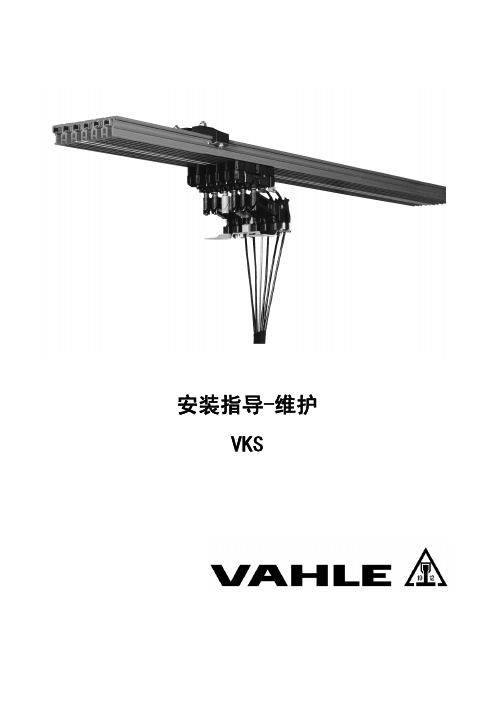
安装指导-维护VKS外部进行安装。
近电源的合适位置。
连接电缆不能限制滑线系统的自膨胀和收缩。
安装图请遵循表格(- 2 -第一个吊夹距离滑线末端不超过每个滑线段需至少安装两个吊夹。
确保滑线的槽钩每段必须装有固定支架。
固定支架间的连接栓的弹簧必须朝向滑线侧面倒角。
- 3 -有对滑线损坏的风险!连接栓的布置如图(在滑线所规定的最大温度范围内(吊夹,连接帽,端供电等之间的距离至少达到- 4 -铜条固定在- 5 -端帽离第一个或者最后一个吊夹的距离按标准,滑线装有线供电。
滑线不与端端供电根据电缆连接到接线夹。
- 6 -线供电 VNS打开预先安装在滑线上的线供电的盖子。
按照要求对金属线剥皮和剪切。
把接线片安装到单根金属线上去,连接电缆穿过电缆封管。
用六角螺丝(M10;M5),弹簧垫片和六角螺母把接线片和接头栓相连。
(G18)扭矩按照DIN VDE 0220 T2M 10 = 44 NmM 5 = 5 Nm旋紧电缆封盖使电缆密封。
(G19) 装上盒盖并关闭。
(G20)线供电 VLS打开预先安装在滑线上的线供电的盖子。
按照要求对金属线剥皮和剪切。
把接线片安装到单根金属线上去。
超过100A 时,使用双孔接线片(发货内含有)。
把带有间隔管的连接螺丝插进准备好的滑线内。
用六角螺丝(M10;M5),弹簧垫片和六角螺母把接线片和接头栓相连。
(G21)扭矩 M6 = 7 Nm电缆标准接口为左接口,右接口也可用。
. 让电缆通过预定破口处的接线盖。
孔的直径是 11mm 。
盖上接线盖,注意电线线路。
(G22) 用两个螺丝拴紧接线盖。
(G23)- 7 -电流集电器把集电器安装到移动设备的牵引点。
相线相反会导致损坏的风险。
确保集电器正确的定位。
集电器支架对于集电器,安装支架必须设计得与滑线的轴向平行,并对接触面有正确的角度。
在预定的方位安装集电器。
(G24)电流集电器的安装高度”H”(S1)如表格T5,T6以及S4,S5,S6所示。
Cutler-Hammer Type SL中高压电气接触器机械锁附件说明书

This instruction book should not be considered all-inclu-sive regarding installation, adjustment, and maintenance procedures.A typical control schematic for a mechanically latched contactor is shown in Figure 2.Figure 2: Typical schematic for latched contactorEffective 4/00I.B. 48020Page 2Effective4/00Figure 3: Mechanical latch kit Contractor Moving Armature (not part of kit)Roller Bracket and Bearing AssemblyMain Latch AssemblyI.B. 48020Page 3Effective4/00LATCH REMOVAL1.Remove latch control wires from terminals 7 & 8 oncontactor coil control board.2.Remove the four 8mm x 1.25 bolts from the undersideof the base plate that secure the latch assembly to the base plate.3.Remove the two 6mm x 1.0 bolts from the front of thecontactor that secure the roller bracket assembly to the armature plate.COIL CHECKOUT AND REPLACEMENTIf the contactor fails to open when the unlatch coil is energized, the coil may be faulty. T o determine if the coil has the proper resistance, connect an ohmmeter across the coil leads where they are connected to the bridge rectifier. Refer to table I for the correct impedance for the different voltage coils.TABLE I: UNLATCH COIL IMPEDANCE Coil VoltsImpedance 240.77 – 0.95482.95 –3.55110/120/12510.97 – 11.19220/24044.57 – 54.57If the coil impedance is not within the ranges in table I, it must be replaced. Follow the steps below for replace-ment.1.Remove latch control wires from terminals 7 & 8 oncontactor coil control board.2.Remove the four 8mm x 1.25 bolts from the undersideof the base plate that secure the latch assembly to the base plate.3.Remove latch coil core retaining bolt (8mm x 1.25),Figure 6, and remove all components secured by this bolt.4.Remove the 4mm x .7 screw securing full bridge diodeto latch coil bracket.5.Remove old coil from core.6.Insert coil core into new coil, insuring rubber gasket isbetween core and coil bobbin.7.Install 4mm x .7 screw securing diode to latch coilbracket and tighten to 9 lb-in. Do not over tighten,cracking of diode housing could result.8.Reassemble all components removed in step 3,insuring steel shim is between coil core and coil core bracket, and secure 8mm x 1.25 bolt to latch base plate. Insure all components are correctly aligned and the coil wires are not binding or pinched, Figure 7.9.Reinstall latch assembly and adjust as described insteps 3 to 8 in section on Installation .Figure 5: Set gap between roller bearing and cam to .5mm(.020 in.)Figure 6: Coil core retaining boltLatch Release TabI.B. 48020 Page 4。
- 1、下载文档前请自行甄别文档内容的完整性,平台不提供额外的编辑、内容补充、找答案等附加服务。
- 2、"仅部分预览"的文档,不可在线预览部分如存在完整性等问题,可反馈申请退款(可完整预览的文档不适用该条件!)。
- 3、如文档侵犯您的权益,请联系客服反馈,我们会尽快为您处理(人工客服工作时间:9:00-18:30)。
VC12真空接触器用户使用说明书威斯汀豪斯电气(上海)有限公司Westinghouse Electric Shanghai Co.,LTD目录1 概述 (2)1.1 总则 (2)1.2 可提供的形式 (2)1.3 应用领域 (2)1.4 依据标准 (2)1.5 使用条件 (2)1.6 主要技术特性 (3)1.7 结构及原理 (3)1.7.1 主体结构 (3)1.7.2 灭弧原理 (4)1.7.3 动作原理 (4)2 熔断器选用说明(仅供参考) (4)2.1 熔断器 (4)2.2 电动机保护熔断器的选用 (4)2.3 变压器保护熔断器的选用 (4)2.4 熔断器使用 (5)3 技术参数.............................. 5 3.1 技术参数 (5)3.2 机械特性参数 (6)3.3 操动机构技术参数 (6)4. 外形尺寸 (7)4.1 固定式接触器 (7)4.2 手车式接触器 (7)5 电气原理图 (8)5.1固定式接触器的电气原理图 (8)5.2 手车式接触器的电气原理图 (9)5.3 图中所表示的操作状态 (11)5.4 说明 (11)6 安装、调试与操作 (11)7 维护与保养 (12)8 运输与储存 (12)9 随机文件及附件 (13)10 订货须知 (13)11 安全注意事项 (13)1 概述1.1 总则由威斯汀豪斯电气(上海)有限公司生产的新一代电磁操动机构的三相接触器——VC12真空接触器,主要用于额定工作电压12kV以下,额定频率50Hz/60Hz的三相交流系统中需要大量分、合闸操作循环的场合,同时又是特别适用于频繁操作的理想电器。
VC12真空接触器主要由真空灭弧室、电磁操动机构以及其它辅助部件构成。
通过电磁操动机构控制来实现接触器的合闸操作,分闸操作则由分闸弹簧实现。
其结构紧凑、在无需经常维护的条件下仍保证其长久的电气和机械寿命。
VC12真空接触器与旧系列的接触器有着良好的互换性,同时它附件的通用性强,易于组装成不同的配置。
1.2 可提供的形式VC12真空接触器具有电气自保持和机械自保持两种配置,可提供以下两种结构形式:⏹固定式⏹手车式(配置熔断器支座)手车式接触器主要由固定式接触器和特定的底盘手车组成。
手车式接触器均装设熔断器支座,以便熔断器的安装。
熔断器支座上都装有联动脱扣机构,保证接触器在即便只有一相熔断器熔断时也能联动分闸(通常随机械保持接触器配套供应)。
同样即使有一相熔断器未安装时,该装置也可防止接触器合闸。
1.3 应用领域VC12接触器在正常使用条件下,只要在接触器的技术参数范围内,它就可以保证安全可靠地运用于相应电压等级的电网中,并广泛应用于电力工业、工矿企业、发电厂、海运等领域电器设备的控制和保护。
VC12接触器的真空灭弧室具有卓越的开断性能,使接触器能在恶劣的环境下运行。
它适合控制和保护(配合熔断器)电机、变压器、电容器组等。
1.4 依据标准VC12真空接触器符合大部分工业国家的标准,并完全符合以下标准:国际电工委员会标准:⏹IEC 60470 高压交流接触器⏹IEC 60632-1 高压交流起动器⏹IEC 60282-1 高压熔断器第一部分电流限定熔断器中国国家标准:⏹GB/T 14808-2001 《交流高压接触器和基于接触器的电动机起动器》⏹GB/ 11022-1999《高压开关设备和控制设备标准的共用技术要求》熔断器的尺寸以及撞击器型号符合DIN 43625和BS2692标准,电气性能符合IEC 60282和GB 15166.2标准。
1.5 使用条件1.5.1 正常使用条件:1)周围空气温度不超过40ºC,且在24h内测得得平均值不超过35ºC。
最低周围空气温度-15ºC。
2)海拔高度不超过1000m。
3)周围空气没有明显的受到尘埃、烟、腐蚀性和/或可燃性气体、蒸气或盐雾的污染。
4)湿度条件如下:——24h 内测得的相对湿度的平均值不超过95%;——24h 内测得的水蒸气压力的平均值不超过2.2kPa;——月相对湿度平均值不超过90%;——月水蒸气压力平均值不超过1.8kPa 。
5) 在二次系统中感应的电磁干扰的幅值不超过1.6kV 。
6) 地震烈度不超过8度。
1.5.2 特殊使用条件:如果使用条件和这些正常使用条件不同,有特殊要求的请与我们联系再达成适当的协议。
1.6 主要技术特性VC12真空接触器主要优点如下: ⏹ 极少量维护 ⏹ 适合频繁操作⏹ 较长的电气和机械寿命 ⏹ 远方控制 ⏹ 互换性强⏹ 适合安装于成套式变电站和开关柜⏹ 电气自保持有专为合闸电磁铁提供的宽电压电源模块1.7 结构及原理1.7.1 主体结构VC12真空接触器结构采用模块叠加式总体结构布局,独特新颖、简单、紧凑、能耗和噪音低、操作可靠性高、产品适应性强,用户可以自由选择固定式、手车式等形式,不需经过调试可直接投入使用。
VC12真空接触器的主回路与操动机构采用一体化设计,三相主回路的真空灭弧室布置在整体浇注的绝缘框架中,使每相回路不受外界恶劣环境的影响,能够得到很好的绝缘性能和保护,并显著提高了相间的绝缘水平。
其结构紧凑、在无需经常维护的条件下仍保证其长久的电气和机械寿命。
绝缘框架真空灭弧室合闸锁扣分闸电磁铁脱扣线圈手动分闸杆分闸弹簧基座合闸电磁铁绝缘翘板触头压力弹簧合闸线圈图1 1.7.2 开断原理接触器主触头在陶瓷的真空灭弧室中操作,灭弧室的真空度高达1.33X10⁻⁴Pa。
接触器分闸时,真空灭弧室的动、静触头快速地开断。
在分闸过程中高温触头之间产生的金属蒸汽使电弧持续到电流第一次过零点。
在电流过零点时,金属蒸汽迅速凝结使动静触头之间重新建立起很高的电介质强度,维持很高的瞬态恢复电压值。
因为接触器的截流值不高,对于切合已经启动的电动机仅产生很低无危害设备的过电压。
1.7.3 动作原理真空接触器通过电磁操动机构控制而实现接触器的合闸操作,分闸操作则由分闸弹簧实现。
对带有锁扣装置的机械自保持式真空接触器来说由机械合闸锁扣装置使接触器保持合闸状态。
同时将分闸弹簧压缩,为分闸做准备。
分闸时,分闸电磁铁动作使合闸锁扣装置解扣,由分闸弹簧驱动操作机构完成分闸。
(见图1)手车式接触器每完成一次合分操作,面板上的合分指示牌将作出相应的指示,同时接触器若安装计数器的将自动记录操作次数。
真空接触器具有手动分闸操作功能。
一般情况下上述手动操作功能只能在空载调试和检测时使用。
2 熔断器的选用说明(仅供参考)为了可靠实现短路保护,给接触器配上合适的限流熔断器是十分必要的。
这种方案意味着负载侧因限流,用户不必因相应的增容而更换设备。
2.1熔断器熔断器符合GB/15166.2《交流高压熔断器限流式熔断器》标准的规定,熔断器安装在熔断器盒中,串联在交流真空接触器和负载回路中。
熔断器对变压器、电动机、电压互感器、电容器起到限流保护。
短路保护通过熔断器实现,它由交流高压真空接触器和熔断器的联锁配合来实现。
2.2电动机保护熔断器的选用在电动机保护选择熔断器时,应确定使用条件:额定电压:必须大于工作电压。
短路电流:熔断器具有短路限流特性,负载只承受较小的短路电流。
额定电流:用于直流起动的熔断器额定电流的使用按如下公式:ly=NInδ其中:N:起动电流与满载电流之比,通常N=6;In:电动机满载电流;Iy:在起动时间内的电流值;δ:综合系数如表。
(n=每小时启动次数)2.3变压器保护熔断器的选用交流真空接触器与熔断器配合,可以避免使用较大的熔断器,同时能够对变压器低压绕组和低压绕组与二次侧断路器之间连接母线故障进行保护。
变压器保护熔断器可以按照下表选用:2.4熔断器的使用使用前应检查外观是否完整、良好、清洁,安装方向是否正确。
熔断器支座框架配有联动脱扣机构,即便只有一相熔断器熔断时,也能使接触器联动跳闸。
同样,如果有一相熔断器未安装时,该装置也能防止接触器合闸。
当组合电器遇到三相故障操作时,考虑到熔断器的动作误差时间。
只要某一相熔断器熔断后,其余相的熔断器即便外观完好,由于通过过电流的原因,三个熔断器均应更换。
更换熔断器必须保证熔断器在不带电的情况下更换。
正常运行的熔断器,应定期进行检查,其使用寿命一般在二十年。
3 技术参数3.1技术参数真空接触器技术参数1 额定电压 kV 12 2 额定绝缘水平 雷电冲击耐受电压(峰值) 753 工频耐受电压(1min)42 5 额定电流 A 400 11 额定工作方式 长期工作制 15 每相回路电阻 μΩ≤150(真空接触器-熔断器)F-C 组合电器技术参数1 额定电压 kV 3.67.212 2 额定绝缘水平 雷电冲击耐受电压(峰值) 60 75 3 工频耐受电压(1min)32425 额定电流 A 取决于熔断器的额定电流7 额定交接电流 A ≤315010 熔断器的最大额定电流(可选)A50-40025-3156.3-224备注:表中 * 机械自保持的机械寿命每30万次需更换机械锁扣。
3.2 机械特性参数1 相间中心距 mm 150±0.52 触头开距 6±13 超行程 1.5±0.5ms 7 分闸时间 机械自保持≤70 电气自保持≤100 8 合闸弹跳时间 ≤2 9 三相分合闸同期性 ≤2 11重量kg98*备注:表中分、合闸时间的数值是不包括继电器动作时间的数值;带*的数值不包括熔芯。
1 额定操作电压、电流机械自保持220V 合闸电流 5A 分闸电流 3.6A 2 110V 合闸电流 10A 分闸电流 5.6A 3 电气自保持220V 保持电流0.5A 5短时最高操作频率 次/h≯1200备注:表中的数值为近似值。
4 外形尺寸4.1固定式接触器图24.2手车式接触器图3动、静触头啮合尺寸不得小于15mm ,一次相间距为150mm可选用熔断器电流(A) 50~40025~355 6.3~200额定开断电流(kA) 50 配合静触头尺寸(mm)φ355 电气原理图5.1 固定式接触器原理图固定式机械自保持接触器原理图固定式电气自保持接触器原理图5.2 手车式接触器原理图手车式机械自保持接触器原理图手车式电气自保持接触器原理图5.3图中所表示的操作状态上述原理图表示的是以下状态的情况:⏹接触器分闸⏹电路处于未储能状态⏹熔断器未熔断VC12型户内高压真空接触器订货选项⏹特殊需要:⏹⏹⏹⏹订货方签字(盖章)日期5.4说明考虑到产品更新以及客户的不同需求,请参照提供给每台产品的电气原理图。
XT =端子排HK1~8 =辅助开关S8 S9 =底盘车位置开关S1 S2 =微动开关(熔芯)HQ1 HQ2 =合闸线圈JX1~3 =接插件KM1 =合闸继电器KM2 =分闸继电器AU =宽电压模块PC =计数器TQ =脱扣线圈T =航空插头6 安装、调试与操作在安装时,应使用适当的起吊工具,吊运时按作业标志要求,小心轻放、防震、勿倒置,同时固定式接触器安装平面与水平的倾角不大于5度或安装平面与水平面的倾角在90度正负5度范围内。